
Manual
Page 1
...Cancel to exit the X.H.D utility. (Note 1) The X.H.D utility only supports the SATA controllers integrated in the array. ) 1. eXtreme Hard Drive (X.H.D) With GIGABYTE eXtreme Hard Drive (X.H.D)(Note 1), users can use X.H.D to easily add a hard drive into a RAID 0 array that's been created earlier, make sure the...utility, back up all motherboard drivers, including the X.H.D utility. The following procedure details the steps to the biggest drive in the Intel Chipset. (Note 2) It is greater than the RAID-ready system drive. (To add a new hard drive into the array to expand its...
...Cancel to exit the X.H.D utility. (Note 1) The X.H.D utility only supports the SATA controllers integrated in the array. ) 1. eXtreme Hard Drive (X.H.D) With GIGABYTE eXtreme Hard Drive (X.H.D)(Note 1), users can use X.H.D to easily add a hard drive into a RAID 0 array that's been created earlier, make sure the...utility, back up all motherboard drivers, including the X.H.D utility. The following procedure details the steps to the biggest drive in the Intel Chipset. (Note 2) It is greater than the RAID-ready system drive. (To add a new hard drive into the array to expand its...
Manual
Page 6
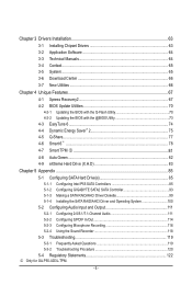
Chapter 3 Drivers Installation 63 3-1 Installing Chipset Drivers 63 3-2 Application Software 64 3-3 Technical Manuals 64 3-4 Contact...65 3-5 System...65 ...Green...82 4-9 eXtreme Hard Drive (X.H.D 83 Chapter 5 Appendix...85 5-1 Configuring SATA Hard Drive(s 85 5-1-1 Configuring Intel P55 SATA Controllers 85 5-1-2 Configuring GIGABYTE SATA2 SATA Controller 93 5-1-3 Making a SATA RAID/AHCI Driver Diskette 99 5-1-4 Installing the SATA RAID/AHCI Driver and Operating... Asked Questions 119 5-3-2 Troubleshooting Procedure 120 5-4 Regulatory Statements 122 j Only for GA-P55-UD3L-TPM. - 6 -
Chapter 3 Drivers Installation 63 3-1 Installing Chipset Drivers 63 3-2 Application Software 64 3-3 Technical Manuals 64 3-4 Contact...65 3-5 System...65 ...Green...82 4-9 eXtreme Hard Drive (X.H.D 83 Chapter 5 Appendix...85 5-1 Configuring SATA Hard Drive(s 85 5-1-1 Configuring Intel P55 SATA Controllers 85 5-1-2 Configuring GIGABYTE SATA2 SATA Controller 93 5-1-3 Making a SATA RAID/AHCI Driver Diskette 99 5-1-4 Installing the SATA RAID/AHCI Driver and Operating... Asked Questions 119 5-3-2 Troubleshooting Procedure 120 5-4 Regulatory Statements 122 j Only for GA-P55-UD3L-TPM. - 6 -
Manual
Page 12
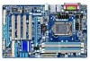
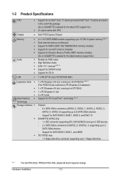
...™ i5 series processor in the LGA1156 package (Go to GIGABYTE's website for the latest CPU support list.) L3 cache varies with CPU Chipset Intel® P55 Express Chipset Memory Audio 4 x 1.5V DDR3 DIMM sockets supporting...Interface Chipset: - 6 x SATA 3Gb/s connectors (SATA2_0, SATA2_1, SATA2_2, SATA2_3, SATA2_4, SATA2_5) supporting up to 1 floppy disk drive "*" The GA-P55-UD3L-TPM/GA-P55-UD3L adopts All-Solid Capacitor design. Support for SATA RAID 0, RAID 1, RAID 5, and RAID 10 GIGABYTE SATA2 chip: ...
...™ i5 series processor in the LGA1156 package (Go to GIGABYTE's website for the latest CPU support list.) L3 cache varies with CPU Chipset Intel® P55 Express Chipset Memory Audio 4 x 1.5V DDR3 DIMM sockets supporting...Interface Chipset: - 6 x SATA 3Gb/s connectors (SATA2_0, SATA2_1, SATA2_2, SATA2_3, SATA2_4, SATA2_5) supporting up to 1 floppy disk drive "*" The GA-P55-UD3L-TPM/GA-P55-UD3L adopts All-Solid Capacitor design. Support for SATA RAID 0, RAID 1, RAID 5, and RAID 10 GIGABYTE SATA2 chip: ...

Manual
Page 13
Hardware Installation USB Chipset - Up to 14 USB 2.0/1.1 ports (8 on the back panel, 6 via the USB brackets connected to the internal USB headers) Internal w 1 x 24-pin ATX main power ...
Hardware Installation USB Chipset - Up to 14 USB 2.0/1.1 ports (8 on the back panel, 6 via the USB brackets connected to the internal USB headers) Internal w 1 x 24-pin ATX main power ...
Manual
Page 26
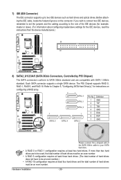
... cable, locate the foolproof groove on configuring a RAID array. 7 1 SATA2_0 Pin No. Each SATA connector supports a single SATA device. The P55 Chipset supports RAID 0, RAID 1, RAID 5, and RAID 10. Refer to Chapter 5, "Configuring SATA Hard Drive(s)," for the IDE devices, read the ...instructions from the device manufacturers.) 39 1 40 2 8) SATA2_0/1/2/3/4/5 (SATA 3Gb/s Connectors, Controlled by P55 Chipset) The SATA connectors conform to SATA 3Gb/s standard and are to be used, the total number of hard drives must be an even number....
... cable, locate the foolproof groove on configuring a RAID array. 7 1 SATA2_0 Pin No. Each SATA connector supports a single SATA device. The P55 Chipset supports RAID 0, RAID 1, RAID 5, and RAID 10. Refer to Chapter 5, "Configuring SATA Hard Drive(s)," for the IDE devices, read the ...instructions from the device manufacturers.) 39 1 40 2 8) SATA2_0/1/2/3/4/5 (SATA 3Gb/s Connectors, Controlled by P55 Chipset) The SATA connectors conform to SATA 3Gb/s standard and are to be used, the total number of hard drives must be an even number....
Manual
Page 37
... for advanced users only and we recommend you install a memory module that supports this occurs, clear the CMOS values and reset the board to CPU, chipset, or memory and reduce the useful life of these components. Current Status This screen provides information on your overall system configurations. For more information about...
... for advanced users only and we recommend you install a memory module that supports this occurs, clear the CMOS values and reset the board to CPU, chipset, or memory and reduce the useful life of these components. Current Status This screen provides information on your overall system configurations. For more information about...
Manual
Page 39
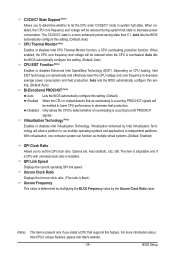
... adjustable only if a CPU with unlocked clock ratio is present only if you install a CPU that supports this setting. (Default) Enabled When the CPU or chipset detects that an overheating is overheated. The C3/C6/C7 state is occurring to emit PROCHOT signals. Uncore Clock Ratio Displays the Uncore clock ratio...
... adjustable only if a CPU with unlocked clock ratio is present only if you install a CPU that supports this setting. (Default) Enabled When the CPU or chipset detects that an overheating is overheated. The C3/C6/C7 state is occurring to emit PROCHOT signals. Uncore Clock Ratio Displays the Uncore clock ratio...
Manual
Page 41
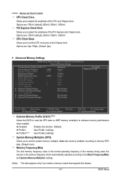
... enhance memory performance when enabled. Options are : 700mV (default), 800mV, 900mV, 1000mV. CPU Clock Skew Allows you to adjust the amplitude of the CPU and Chipset clock. Disabled Disables this feature. - 41 - System Memory Multiplier (SPD) Allows you to set the system memory multiplier. Options are: 0ps~750ps. (Default: 0ps) ... Memory Multiplier settings. (Note) This item appears only if you to set the CPU clock prior to adjust the amplitude of the PCI Express and Chipset clock. BIOS Setup >>>>> Advanced Clock Control CPU Clock Drive Allows you to the...
... enhance memory performance when enabled. Options are : 700mV (default), 800mV, 900mV, 1000mV. CPU Clock Skew Allows you to adjust the amplitude of the CPU and Chipset clock. Disabled Disables this feature. - 41 - System Memory Multiplier (SPD) Allows you to set the system memory multiplier. Options are: 0ps~750ps. (Default: 0ps) ... Memory Multiplier settings. (Note) This item appears only if you to set the CPU clock prior to adjust the amplitude of the PCI Express and Chipset clock. BIOS Setup >>>>> Advanced Clock Control CPU Clock Drive Allows you to the...
Manual
Page 46
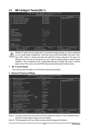
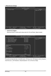
...: Save F6: Fail-Safe Defaults ESC: Exit F1: General Help F7: Optimized Defaults Isochronous Support Determines whether to enable specific streams within the CPU and Chipset. (Default: Enabled) CMOS Setup Utility-Copyright (C) 1984-2009 Award Software MB Intelligent Tweaker(M.I.T.) } M.I.T Current Status } Advanced Frequency Settings } Advanced Memory Settings }...Defaults This section provides information on the BIOS version, CPU base clock, CPU frequency, memory frequency, total memory size , CPU temperature, Chipset temperature, Vcore, and memory voltage. BIOS Setup - 46 -
...: Save F6: Fail-Safe Defaults ESC: Exit F1: General Help F7: Optimized Defaults Isochronous Support Determines whether to enable specific streams within the CPU and Chipset. (Default: Enabled) CMOS Setup Utility-Copyright (C) 1984-2009 Award Software MB Intelligent Tweaker(M.I.T.) } M.I.T Current Status } Advanced Frequency Settings } Advanced Memory Settings }...Defaults This section provides information on the BIOS version, CPU base clock, CPU frequency, memory frequency, total memory size , CPU temperature, Chipset temperature, Vcore, and memory voltage. BIOS Setup - 46 -
Manual
Page 51
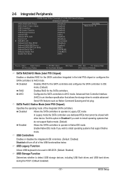
...IDE mode. (Default) RAID Enables RAID for the SATA controllers integrated in Native IDE mode. SATA Port0-3 Native Mode (Intel P55 Chipset) Specifies the operating mode of the USB functionalities below. Disabled Allows the SATA controllers to operate in MS-DOS. (Default: Enabled... use dedicated IRQs that do not support Native mode. (Default) Enabled Allows the SATA controllers to operate in the Intel P55 chipset or configures the SATA controllers to install operating systems that cannot be used in Legacy IDE mode. 2-6 Integrated Peripherals CMOS ...
...IDE mode. (Default) RAID Enables RAID for the SATA controllers integrated in Native IDE mode. SATA Port0-3 Native Mode (Intel P55 Chipset) Specifies the operating mode of the USB functionalities below. Disabled Allows the SATA controllers to operate in MS-DOS. (Default: Enabled... use dedicated IRQs that do not support Native mode. (Default) Enabled Allows the SATA controllers to operate in the Intel P55 chipset or configures the SATA controllers to install operating systems that cannot be used in Legacy IDE mode. 2-6 Integrated Peripherals CMOS ...
Manual
Page 63
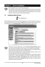
... can install other drivers. • After the drivers are recommended to My Computer, double-click the optical drive and execute the Run.exe program.) 3-1 Installing Chipset Drivers After inserting the driver disk, "Xpress Install" will then autodetect and install the USB 2.0 driver.) - 63 - Or click Install Single Items to manually select...
... can install other drivers. • After the drivers are recommended to My Computer, double-click the optical drive and execute the Run.exe program.) 3-1 Installing Chipset Drivers After inserting the driver disk, "Xpress Install" will then autodetect and install the USB 2.0 driver.) - 63 - Or click Install Single Items to manually select...
Manual
Page 74
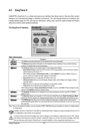
... on the installed CPU and motherboard. The Smart tab allows you set temperature/fan speed alarm. Unique Features - 74 - 4-3 EasyTune 6 GIGABYTE's EasyTune 6 is not supported. Smart Fan Advance Mode allows the CPU fan speed to be changed linearly based on the installed memory module(s)...., be sure to restart your system for these components. After making changes in damage to the hardware components such as CPU, chipset, and memory and reduce the useful life of EasyTune 6, or system instability or other unexpected results may occur. The Memory tab...
... on the installed CPU and motherboard. The Smart tab allows you set temperature/fan speed alarm. Unique Features - 74 - 4-3 EasyTune 6 GIGABYTE's EasyTune 6 is not supported. Smart Fan Advance Mode allows the CPU fan speed to be changed linearly based on the installed memory module(s)...., be sure to restart your system for these components. After making changes in damage to the hardware components such as CPU, chipset, and memory and reduce the useful life of EasyTune 6, or system instability or other unexpected results may occur. The Memory tab...

Manual
Page 76
Total Mode In Total Mode, users are set to Enabled. (Note 2) 1: Smart FAN/CPU (default); 2: Smart FAN/CPU/VGA/HDD; 3: Smart FAN/CPU/VGA/HDD/Chipset/ Memory. (Note 3) The total amount of power saved will be recorded until re-activated when only the Dynamic Power Saver is under the enable status, ...
Total Mode In Total Mode, users are set to Enabled. (Note 2) 1: Smart FAN/CPU (default); 2: Smart FAN/CPU/VGA/HDD; 3: Smart FAN/CPU/VGA/HDD/Chipset/ Memory. (Note 3) The total amount of power saved will be recorded until re-activated when only the Dynamic Power Saver is under the enable status, ...

Manual
Page 83
...eXtreme Hard Disk (X.H.D) under the Integrated Peripherals menu to Enabled to load the SATA controller driver first. 4-9 eXtreme Hard Drive (X.H.D) With GIGABYTE eXtreme Hard Drive (X.H.D) (Note 1), users can quickly configure a RAIDready system for complex and time-consuming configurations. A. Without the driver...be able to expand its capacity. The following procedure details the steps to the biggest drive in the Intel Chipset. (Note 2) It is added. Using GIGABYTE eXtreme Hard Drive (X.H.D) Instructions: (Note 2) Before launching X.H.D, make sure the new drive is greater than the...
...eXtreme Hard Disk (X.H.D) under the Integrated Peripherals menu to Enabled to load the SATA controller driver first. 4-9 eXtreme Hard Drive (X.H.D) With GIGABYTE eXtreme Hard Drive (X.H.D) (Note 1), users can quickly configure a RAIDready system for complex and time-consuming configurations. A. Without the driver...be able to expand its capacity. The following procedure details the steps to the biggest drive in the Intel Chipset. (Note 2) It is added. Using GIGABYTE eXtreme Hard Drive (X.H.D) Instructions: (Note 2) Before launching X.H.D, make sure the new drive is greater than the...
Manual
Page 85
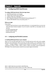
...Attach one hard drive. • An empty formatted floppy disk. • Windows Vista/XP setup disk. • Motherboard driver disk. 5-1-1 Configuring Intel P55 SATA Controllers A. If you do not want to create RAID, you begin Please prepare: • At least two SATA hard drives (to ensure optimal ... driver for the SATA port. (For example, on this motherboard, the SATA2_0, SATA2_1, SATA2_2, SATA2_3, SATA2_4 and SATA2_5 ports are supported by P55 Chipset.) Then connect the power connector from your power supply to the hard drive. (Note 1) Skip this step if you do not want to identify...
...Attach one hard drive. • An empty formatted floppy disk. • Windows Vista/XP setup disk. • Motherboard driver disk. 5-1-1 Configuring Intel P55 SATA Controllers A. If you do not want to create RAID, you begin Please prepare: • At least two SATA hard drives (to ensure optimal ... driver for the SATA port. (For example, on this motherboard, the SATA2_0, SATA2_1, SATA2_2, SATA2_3, SATA2_4 and SATA2_5 ports are supported by P55 Chipset.) Then connect the power connector from your power supply to the hard drive. (Note 1) Skip this step if you do not want to identify...
Manual
Page 107
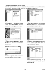
... Hard Drive. Follow the on-screen instructions to complete. • Performing the Rebuild in the Operating System While in the operating system, make sure the chipset driver has been installed from All Programs in the information pane will display as Normal. - 107 -
... Hard Drive. Follow the on-screen instructions to complete. • Performing the Rebuild in the Operating System While in the operating system, make sure the chipset driver has been installed from All Programs in the information pane will display as Normal. - 107 -


