Manual
Page 4
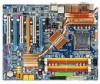
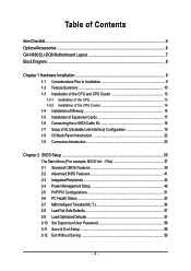
Table of Contents ItemChecklist ...6 OptionalAccessories ...6 GA-N680SLI-DQ6 Motherboard Layout 7 Block Diagram ...8 Chapter 1 Hardware Installation 9 1-1 Considerations Prior to Installation 9 1-2 Feature Summary 10 1-3 Installation of the CPU and CPU Cooler 13 1-3-1 Installation of the CPU 13 1-3-2 Installation of the CPU Cooler 14 1-4 Installation of Memory 15 1-5 Installation of Expansion Cards 17 1-6 Connecting the e-SATA Cable Kit...
Table of Contents ItemChecklist ...6 OptionalAccessories ...6 GA-N680SLI-DQ6 Motherboard Layout 7 Block Diagram ...8 Chapter 1 Hardware Installation 9 1-1 Considerations Prior to Installation 9 1-2 Feature Summary 10 1-3 Installation of the CPU and CPU Cooler 13 1-3-1 Installation of the CPU 13 1-3-2 Installation of the CPU Cooler 14 1-4 Installation of Memory 15 1-5 Installation of Expansion Cards 17 1-6 Connecting the e-SATA Cable Kit...

Manual
Page 8
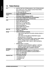
... DIMM LAN RJ45 LAN RJ45 Marvell Marvell 88E8052 88E8056 x1 x1 nVIDIA® nForce 680i SLI Northbridge Dual Channel Memory 1 PCI Express x1 PCIe CLK (100 MHz) PCI Express Bus 4 SATA 3Gb/s GIGABYTE SATA2 x 2 6 SATA 3Gb/s PCI Bus LAN1 LAN2 RJ45 RJ45 Marvell 88E1116 x 2 nVIDIA® nForce 680i SLI Southbridge ATA33/66...
... DIMM LAN RJ45 LAN RJ45 Marvell Marvell 88E8052 88E8056 x1 x1 nVIDIA® nForce 680i SLI Northbridge Dual Channel Memory 1 PCI Express x1 PCIe CLK (100 MHz) PCI Express Bus 4 SATA 3Gb/s GIGABYTE SATA2 x 2 6 SATA 3Gb/s PCI Bus LAN1 LAN2 RJ45 RJ45 Marvell 88E1116 x 2 nVIDIA® nForce 680i SLI Southbridge ATA33/66...
Manual
Page 10
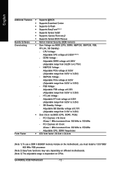
...680i SLI Southbridge - 1 FDD connector supported by I . Supports data RAID 0, RAID 1, RAID 0+1, RAID 5 and JBOD for Serial ATA Š GIGABYTE SATA2 x 2 Controller - 4 SATA 3Gb/s connectors (GSATAII1-0, GSATAII1-1, GSATAII2-0, GSATAII2-1), allowing connection of 6 SATA 3Gb/s devices - Supports data RAID 0,...PCI Express x8 slot Š 1 PCI Express x1 slot Š 3 PCI slots GA-N680SLI-DQ6 Motherboard - 10 - English 1-2 Feature Summary CPU Front Side Bus Chipset LAN Audio IEEE 1394 Storage O.S Support Memory Expanstion Slots Š LGA775 for Intel® CoreTM 2 Extreme quad-core / CoreTM ...
...680i SLI Southbridge - 1 FDD connector supported by I . Supports data RAID 0, RAID 1, RAID 0+1, RAID 5 and JBOD for Serial ATA Š GIGABYTE SATA2 x 2 Controller - 4 SATA 3Gb/s connectors (GSATAII1-0, GSATAII1-1, GSATAII2-0, GSATAII2-1), allowing connection of 6 SATA 3Gb/s devices - Supports data RAID 0,...PCI Express x8 slot Š 1 PCI Express x1 slot Š 3 PCI slots GA-N680SLI-DQ6 Motherboard - 10 - English 1-2 Feature Summary CPU Front Side Bus Chipset LAN Audio IEEE 1394 Storage O.S Support Memory Expanstion Slots Š LGA775 for Intel® CoreTM 2 Extreme quad-core / CoreTM ...
Manual
Page 12
... from 0.05V to 0.35V) - Adjustable CPU, DDRII frequencies Form Factor Š ATX form factor; 30.5cm x 24.4cm (Note 1) To use a DDR II 800/667 memory module on the motherboard, you must install a 1333/1066/ 800 MHz FSB processor. (Note 2) EasyTune functions may vary depending on different motherboards. (Note 3) The adjustable... Bundle Software Š Norton Internet Security (OEM revision) Overclocking Š Over Voltage via BIOS (CPU, DDRII, PCIE) - CPU Voltage : Adjustable CPU voltage at 0.025V (Note 3) - GA-N680SLI-DQ6 Motherboard - 12 -
... from 0.05V to 0.35V) - Adjustable CPU, DDRII frequencies Form Factor Š ATX form factor; 30.5cm x 24.4cm (Note 1) To use a DDR II 800/667 memory module on the motherboard, you must install a 1333/1066/ 800 MHz FSB processor. (Note 2) EasyTune functions may vary depending on different motherboards. (Note 3) The adjustable... Bundle Software Š Norton Internet Security (OEM revision) Overclocking Š Over Voltage via BIOS (CPU, DDRII, PCIE) - CPU Voltage : Adjustable CPU voltage at 0.025V (Note 3) - GA-N680SLI-DQ6 Motherboard - 12 -
Manual
Page 13
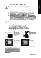
... socket in accordance with the processor specifications. Fig. 2 Remove the plastic covering on the CPU socket to your hardware specifications including the CPU, graphics card, memory, hard drive, etc. Fig. 4 Once the CPU is not recommended that might cause damage to system use, otherwise overheating and permanent damage of Hyper-Threading...
... socket in accordance with the processor specifications. Fig. 2 Remove the plastic covering on the CPU socket to your hardware specifications including the CPU, graphics card, memory, hard drive, etc. Fig. 4 Once the CPU is not recommended that might cause damage to system use, otherwise overheating and permanent damage of Hyper-Threading...

Manual
Page 15
...direction. Reverse the installation steps when you are designed so that memory of similar capacity, specifications and brand be installed in one direction. English 1-4 Installation of Memory Before installing the memory modules, please comply with each slot. Fig.2 Close the plastic ...DIMM sockets to remove the DIMM module. - 15 - The motherboard supports DDRII memory modules, whereby BIOS will automatically detect memory capacity and specifications. Please make sure that the memory used . 2. Memory modules have a foolproof insertion design. If you wish to lock the DIMM ...
...direction. Reverse the installation steps when you are designed so that memory of similar capacity, specifications and brand be installed in one direction. English 1-4 Installation of Memory Before installing the memory modules, please comply with each slot. Fig.2 Close the plastic ...DIMM sockets to remove the DIMM module. - 15 - The motherboard supports DDRII memory modules, whereby BIOS will automatically detect memory capacity and specifications. Please make sure that the memory used . 2. Memory modules have a foolproof insertion design. If you wish to lock the DIMM ...
Manual
Page 16
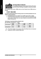
..., and each Channel has two DIMM sockets as following explanations due to be enabled if only one DDRII memory module is installed. 2. DS/SS DDRII2 - GA-N680SLI-DQ6 Motherboard - 16 - Dual Channel mode will double. English Dual Channel Memory Configuration The GA-N680SLI-DQ6 supports the Dual Channel Technology. To enable Dual Channel mode with two or four...
..., and each Channel has two DIMM sockets as following explanations due to be enabled if only one DDRII memory module is installed. 2. DS/SS DDRII2 - GA-N680SLI-DQ6 Motherboard - 16 - Dual Channel mode will double. English Dual Channel Memory Configuration The GA-N680SLI-DQ6 supports the Dual Channel Technology. To enable Dual Channel mode with two or four...

Manual
Page 19
... work seamlessly to allow two graphics cards to configure an SLI system on the GA-N680SLI-DQ6 motherboard. This section introduces steps to operate in parallel and share the work and...installing the graphics card on your system and the two SLI graphics cards. For example: GIGABYTE GV-NX76T256D-RH). English 1-7 Setup of SLI (Scalable Link Interface) Configuration nVIDIA®... check recommended power for different systems. System configuration Processors PCIE x16 video cards DDR memory modules Hard drives/Optical drives Expansion cards USB devices IEEE 1394 devices Required +12V ...
... work seamlessly to allow two graphics cards to configure an SLI system on the GA-N680SLI-DQ6 motherboard. This section introduces steps to operate in parallel and share the work and...installing the graphics card on your system and the two SLI graphics cards. For example: GIGABYTE GV-NX76T256D-RH). English 1-7 Setup of SLI (Scalable Link Interface) Configuration nVIDIA®... check recommended power for different systems. System configuration Processors PCIE x16 video cards DDR memory modules Hard drives/Optical drives Expansion cards USB devices IEEE 1394 devices Required +12V ...
Manual
Page 39
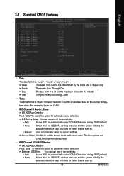
... 6 Master IDE Channel 7 Master [None] [None] [None] [None] [None] [None] [None] [None] Drive A Floppy 3 Mode Support [1.44M, 3.5"] [Disabled] Halt On [All, But Keyboard] Base Memory Extended Memory 1664K 511M : Move Enter: Select F5: Previous Values +/-/PU/PD: Value F10: Save F6: Fail-Safe Defaults ESC: Exit F1: General Help F7: Optimized Defaults...
... 6 Master IDE Channel 7 Master [None] [None] [None] [None] [None] [None] [None] [None] Drive A Floppy 3 Mode Support [1.44M, 3.5"] [Disabled] Halt On [All, But Keyboard] Base Memory Extended Memory 1664K 511M : Move Enter: Select F5: Previous Values +/-/PU/PD: Value F10: Save F6: Fail-Safe Defaults ESC: Exit F1: General Help F7: Optimized Defaults...
Manual
Page 40
... is present during power up. Base Memory The POST of the BIOS. Extended Memory The BIOS determines how much extended memory is determined by POST (Power On Self Test) of the BIOS will not stop if an error is detected during the POST. GA-N680SLI-DQ6 Motherboard - 40 - English Access Mode... Capacity Cylinder Head Use this to set the access mode for any error that has been installed in the computer. The two options are: Large/Auto(default:Auto) Capacity of the base memory is 3 mode Floppy Drive...
... is present during power up. Base Memory The POST of the BIOS. Extended Memory The BIOS determines how much extended memory is determined by POST (Power On Self Test) of the BIOS will not stop if an error is detected during the POST. GA-N680SLI-DQ6 Motherboard - 40 - English Access Mode... Capacity Cylinder Head Use this to set the access mode for any error that has been installed in the computer. The two options are: Large/Auto(default:Auto) Capacity of the base memory is 3 mode Floppy Drive...
Manual
Page 41
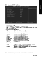
... access to Setup page if the correct password is not entered at the prompt. (Note) This item will show up , or to 3 (Note) No-Execute Memory Protect (Note) CPU Enhanced Halt (C1E) (Note) CPU Thermal Monitor 2(TM2) (Note) CPU EIST Function (Note) Virtualization Technology (Note) Full Screen LOGO Show Init Display...
... access to Setup page if the correct password is not entered at the prompt. (Note) This item will show up , or to 3 (Note) No-Execute Memory Protect (Note) CPU Enhanced Halt (C1E) (Note) CPU Thermal Monitor 2(TM2) (Note) CPU EIST Function (Note) Virtualization Technology (Note) Full Screen LOGO Show Init Display...
Manual
Page 42
...Default value) Disable CPU Enhanced Halt (C1E) function. PCI Set Init Display First to PCI Express VGA card (the PCIE_16_1 slot). GA-N680SLI-DQ6 Motherboard - 42 - English HDD S.M.A.R.T. Enabled Disabled Enable HDD S.M.A.R.T. Please note that supports this feature is installed. Disabled (Default ...monitor utility is only working for windows XP. (Default value) No-Execute Memory Protect (Note) Enabled Disabled Enable No-Execute Memory Protect function. (Default value) Disable No-Execute Memory Protect function. Limit CPUID Max. If you install a processor that this...
...Default value) Disable CPU Enhanced Halt (C1E) function. PCI Set Init Display First to PCI Express VGA card (the PCIE_16_1 slot). GA-N680SLI-DQ6 Motherboard - 42 - English HDD S.M.A.R.T. Enabled Disabled Enable HDD S.M.A.R.T. Please note that supports this feature is installed. Disabled (Default ...monitor utility is only working for windows XP. (Default value) No-Execute Memory Protect (Note) Enabled Disabled Enable No-Execute Memory Protect function. (Default value) Disable No-Execute Memory Protect function. Limit CPUID Max. If you install a processor that this...

Manual
Page 54
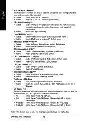
... System Clock Setting CMOS Setup Utility-Copyright (C) 1984-2007 Award Software System Clock Setting SLI-Ready Memory FSB-Memory Clock Mode x FSB-Memory Ratio x CPU Host Frequency (Mhz) Actual CPU Clock (Mhz) x Memory Frequency (Mhz) Actual Memory Clock (Mhz) [Disable] [Auto] Auto Auto 133.3 Auto 800.0 Disable 133.3 800.0 ...+/-/PU/PD: Value F10: Save F6: Fail-Safe Defaults ESC: Exit F1: General Help F7: Optimized Defaults Incorrectly using these components. GA-N680SLI-DQ6 Motherboard - 54 - menu items are for power users only. Please be aware that supports this function.
... System Clock Setting CMOS Setup Utility-Copyright (C) 1984-2007 Award Software System Clock Setting SLI-Ready Memory FSB-Memory Clock Mode x FSB-Memory Ratio x CPU Host Frequency (Mhz) Actual CPU Clock (Mhz) x Memory Frequency (Mhz) Actual Memory Clock (Mhz) [Disable] [Auto] Auto Auto 133.3 Auto 800.0 Disable 133.3 800.0 ...+/-/PU/PD: Value F10: Save F6: Fail-Safe Defaults ESC: Exit F1: General Help F7: Optimized Defaults Incorrectly using these components. GA-N680SLI-DQ6 Motherboard - 54 - menu items are for power users only. Please be aware that supports this function.
Manual
Page 55
...CPU Host Frequency This option is available only when FSB-Memory Clock Mode is Unlinked. 400 ~ 1400 Set Memory Frequency from 100 MHz to 650 MHz. Memory Frequency (Mhz) This option is available only when FSB-Memory Clock Mode is Linked or Unlinked. 100 ~ 650...Options: Disable, CPUOC 0%~CPUOC 5%, CPUOC MAX and Expert FSB-Memory Clock Mode Auto Linked BIOS will automatically setup the FSB-Memory Ratio. (Default value) 1:1 Set FSB-Memory Ratio to 1:1. 5:4 Set FSB-Memory Ratio to 5:4. 3:2 Sync Mode Set FSB-Memory Ratio to 1400 MHz. If you to 150 Mhz. -...
...CPU Host Frequency This option is available only when FSB-Memory Clock Mode is Unlinked. 400 ~ 1400 Set Memory Frequency from 100 MHz to 650 MHz. Memory Frequency (Mhz) This option is available only when FSB-Memory Clock Mode is Linked or Unlinked. 100 ~ 650...Options: Disable, CPUOC 0%~CPUOC 5%, CPUOC MAX and Expert FSB-Memory Clock Mode Auto Linked BIOS will automatically setup the FSB-Memory Ratio. (Default value) 1:1 Set FSB-Memory Ratio to 1:1. 5:4 Set FSB-Memory Ratio to 5:4. 3:2 Sync Mode Set FSB-Memory Ratio to 1400 MHz. If you to 150 Mhz. -...
Manual
Page 56
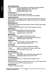
... the voltage settings for the HT-Link between Southbridge and Northbridge. SB Standby Voltage Set the Southbridge standby voltage. The adjustable range is not changeable. GA-N680SLI-DQ6 Motherboard - 56 - Normal Supply SB/PCIE voltage as required. Auto lets BIOS automatically set the system voltages. Normal Set NB/PCIE voltage to Normal. (Default... of the DDR2 voltage, damage to get higher performance. English Robust Graphics Booster Select the options can enhance the VGA graphics card bandwidth to the memory may occur.
... the voltage settings for the HT-Link between Southbridge and Northbridge. SB Standby Voltage Set the Southbridge standby voltage. The adjustable range is not changeable. GA-N680SLI-DQ6 Motherboard - 56 - Normal Supply SB/PCIE voltage as required. Auto lets BIOS automatically set the system voltages. Normal Set NB/PCIE voltage to Normal. (Default... of the DDR2 voltage, damage to get higher performance. English Robust Graphics Booster Select the options can enhance the VGA graphics card bandwidth to the memory may occur.

Manual
Page 65
...fan and North-Bridge Chipset cooling fan, 4) PC health for enhancing system performance, 2) C.I .B. Appendix Featuring several powerful yet easy to GIGABYTE website Display EasyTuneTM 5 Help file Quit or Minimize EasyTuneTM 5 software (Note) EasyTune 5 functions may vary depending on to use tools ...such as 1) Overclocking for monitoring system status.(Note) User Interface Overview Button / Display 1. GIGABYTE Logo 10. Help button 11. and M.I .A. for special enhancement for CPU and Memory, 3) Smart-Fan control for managing fan speed control of CPU frequency Shows the current ...
...fan and North-Bridge Chipset cooling fan, 4) PC health for enhancing system performance, 2) C.I .B. Appendix Featuring several powerful yet easy to GIGABYTE website Display EasyTuneTM 5 Help file Quit or Minimize EasyTuneTM 5 software (Note) EasyTune 5 functions may vary depending on to use tools ...such as 1) Overclocking for monitoring system status.(Note) User Interface Overview Button / Display 1. GIGABYTE Logo 10. Help button 11. and M.I .A. for special enhancement for CPU and Memory, 3) Smart-Fan control for managing fan speed control of CPU frequency Shows the current ...
Manual
Page 66
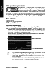
... in the bottom left corner of the screen. GA-N680SLI-DQ6 FAa . . . . :BIOS Setup/Dual BIOS : Xpress Recovery2 : Boot Menu : Qflash 4/12/2007-NF68-6A61IG01C-00 : Xpress Recovery2 1. After Xpress Recovery2 is designed to startup XpressRecovery2..... System storage capacity and the reading/writing speed of system memory 3. Upon system restart, the message which says...
... in the bottom left corner of the screen. GA-N680SLI-DQ6 FAa . . . . :BIOS Setup/Dual BIOS : Xpress Recovery2 : Boot Menu : Qflash 4/12/2007-NF68-6A61IG01C-00 : Xpress Recovery2 1. After Xpress Recovery2 is designed to startup XpressRecovery2..... System storage capacity and the reading/writing speed of system memory 3. Upon system restart, the message which says...
Manual
Page 77
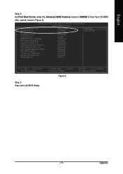
... Boot Device Third Boot Device Password Check HDD S.M.A.R.T. English Step 2: Set First Boot Device under the Advanced BIOS Features menu to CDROM to 3 No-Execute Memory Protect CPU Enhanced Halt (C1E) CPU Thermal Monitor 2(TM2) CPU EIST Function Virtualization Technology Full Screen LOGO Show Init Display First [Press Enter] [CDROM] [Hard...
... Boot Device Third Boot Device Password Check HDD S.M.A.R.T. English Step 2: Set First Boot Device under the Advanced BIOS Features menu to CDROM to 3 No-Execute Memory Protect CPU Enhanced Halt (C1E) CPU Thermal Monitor 2(TM2) CPU EIST Function Virtualization Technology Full Screen LOGO Show Init Display First [Press Enter] [CDROM] [Hard...
Manual
Page 78
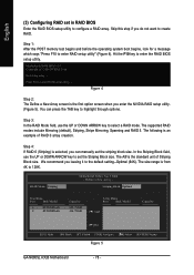
... 111.79GB Array Disks Port Disk Model [ ] Add Capacity [ ] Del [ESC] Quit [F6] Back [F7] Finish [TAB] Navigate [ ] Select [ENTER] Popup Figure 5 GA-N680SLI-DQ6 Motherboard - 78 - Step 1: After the POST memory test begins and before the operating system boot begins, look for a message which says "Press F10 to the default setting--Optimal (64K...
... 111.79GB Array Disks Port Disk Model [ ] Add Capacity [ ] Del [ESC] Quit [F6] Back [F7] Finish [TAB] Navigate [ ] Select [ENTER] Popup Figure 5 GA-N680SLI-DQ6 Motherboard - 78 - Step 1: After the POST memory test begins and before the operating system boot begins, look for a message which says "Press F10 to the default setting--Optimal (64K...
Manual
Page 86
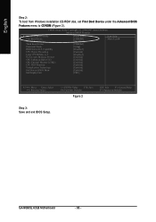
... Boot Device Second Boot Device Third Boot Device Password Check HDD S.M.A.R.T. GA-N680SLI-DQ6 Motherboard - 86 - to CDROM (Figure 2). English Step 2: To boot from Windows installation CD-ROM disk, set First Boot Device under the Advanced BIOS Features menu to 3 No-Execute Memory Protect CPU Enhanced Halt (C1E) CPU Thermal Monitor 2(TM2) CPU EIST...
... Boot Device Second Boot Device Third Boot Device Password Check HDD S.M.A.R.T. GA-N680SLI-DQ6 Motherboard - 86 - to CDROM (Figure 2). English Step 2: To boot from Windows installation CD-ROM disk, set First Boot Device under the Advanced BIOS Features menu to 3 No-Execute Memory Protect CPU Enhanced Halt (C1E) CPU Thermal Monitor 2(TM2) CPU EIST...


