Manual
Page 1
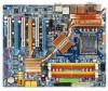
GA-N680SLI-DQ6 Intel® CoreTM 2 Extreme quad-core / CoreTM 2 Quad / Intel® CoreTM 2 Extreme dual-core / CoreTM 2 Duo / Intel® Pentium® Processor Extreme Edition / Intel® Pentium® D / Pentium® 4 LGA775 Processor Motherboard User's Manual Rev. 2001 12ME-N680DQ6-2001R * The WEEE marking on the product indicates this product must not be disposed...
GA-N680SLI-DQ6 Intel® CoreTM 2 Extreme quad-core / CoreTM 2 Quad / Intel® CoreTM 2 Extreme dual-core / CoreTM 2 Duo / Intel® Pentium® Processor Extreme Edition / Intel® Pentium® D / Pentium® 4 LGA775 Processor Motherboard User's Manual Rev. 2001 12ME-N680DQ6-2001R * The WEEE marking on the product indicates this product must not be disposed...
Manual
Page 3
... detailed product information and specifications, please carefully read the "Product User Manual". „ For detailed information related to Gigabyte's unique features, please go to "Technology Guide" section on Gigabyte's website to read or download the information you need. No part of Gigabyte. Product Manual Classification In order to assist in the use of this product...
... detailed product information and specifications, please carefully read the "Product User Manual". „ For detailed information related to Gigabyte's unique features, please go to "Technology Guide" section on Gigabyte's website to read or download the information you need. No part of Gigabyte. Product Manual Classification In order to assist in the use of this product...

Manual
Page 9
.... 6. Hardware Installation When handling the motherboard, avoid touching any hardware, please first carefully read the information in the user manual. 3. Turning on the computer power during the installation process can become damaged as a result of electrostatic discharge (ESD). ...any metal leads or connectors. 3. Product determined to installation, please follow the instructions below: 1. Thus, prior to be an unofficial Gigabyte product. - 9 - Please turn off before unplugging the power supply connector from the motherboard. It is switched off the computer and...
.... 6. Hardware Installation When handling the motherboard, avoid touching any hardware, please first carefully read the information in the user manual. 3. Turning on the computer power during the installation process can become damaged as a result of electrostatic discharge (ESD). ...any metal leads or connectors. 3. Product determined to installation, please follow the instructions below: 1. Thus, prior to be an unofficial Gigabyte product. - 9 - Please turn off before unplugging the power supply connector from the motherboard. It is switched off the computer and...
Manual
Page 14
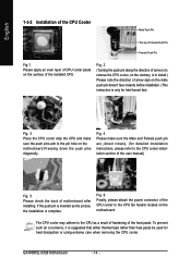
... on the motherboard. Fig. 6 Finally, please attach the power connector of the CPU cooler to the CPU cooler installation section of the user manual) Fig. 5 Please check the back of the heat paste. If the push pin is inserted as a result of hardening of motherboard after ...paste be used for detailed installation instructions, please refer to the CPU fan header located on the motherboard.Pressing down the push pins diagonally. GA-N680SLI-DQ6 Motherboard - 14 - English 1-3-2 Installation of the CPU Cooler Male Push Pin The top of Female Push Pin Female Push Pin Fig.1 Please...
... on the motherboard. Fig. 6 Finally, please attach the power connector of the CPU cooler to the CPU cooler installation section of the user manual) Fig. 5 Please check the back of the heat paste. If the push pin is inserted as a result of hardening of motherboard after ...paste be used for detailed installation instructions, please refer to the CPU fan header located on the motherboard.Pressing down the push pins diagonally. GA-N680SLI-DQ6 Motherboard - 14 - English 1-3-2 Installation of the CPU Cooler Male Push Pin The top of Female Push Pin Female Push Pin Fig.1 Please...

Manual
Page 17
... two graphics cards, please connect the power cable from the computer. Remove your computer resulting from its power source and read the expansion card's installation manual before installing the expansion card in the operating system. Ground yourself to prevent damage to your computer's chassis cover, screws and slot bracket from the...
... two graphics cards, please connect the power cable from the computer. Remove your computer resulting from its power source and read the expansion card's installation manual before installing the expansion card in the operating system. Ground yourself to prevent damage to your computer's chassis cover, screws and slot bracket from the...
Manual
Page 39
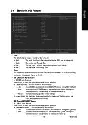
...no IDE/SATA devices are used and the system will skip the automatic detection step and allow for faster system start up . • Manual User can use one of three methods: • Auto Allows BIOS to automatically detect IDE/SATA devices during POST(default) • None... Select this option for faster system start up . - 39 - You can manually input the correct settings. Through Dec. BIOS Setup English 2-1 Standard CMOS Features Date (mm:dd:yy) Time (hh:mm:ss) CMOS Setup Utility-...
...no IDE/SATA devices are used and the system will skip the automatic detection step and allow for faster system start up . • Manual User can use one of three methods: • Auto Allows BIOS to automatically detect IDE/SATA devices during POST(default) • None... Select this option for faster system start up . - 39 - You can manually input the correct settings. Through Dec. BIOS Setup English 2-1 Standard CMOS Features Date (mm:dd:yy) Time (hh:mm:ss) CMOS Setup Utility-...

Manual
Page 54
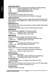
...Voltage SB/PCIE Voltage FSB Voltage Control HT-Link Voltage SB Standby Voltage CPU Voltage Control Normal CPU Vcore [Press Enter] [Auto] [16X] [Manual] [Normal] [Normal] [Normal] [Normal] [Normal] [Normal] [Normal] 1.40000V Item Help Menu Level : Move Enter: Select F5: ...a overclock or overvoltage on CPU, chipsets and memory modules may result in damages or shortened life expectancy to these components. GA-N680SLI-DQ6 Motherboard - 54 - English 2-7 MB Intelligent Tweaker(M.I.T.) CMOS Setup Utility-Copyright (C) 1984-2007 Award Software MB Intelligent Tweaker(M.I .T. ...
...Voltage SB/PCIE Voltage FSB Voltage Control HT-Link Voltage SB Standby Voltage CPU Voltage Control Normal CPU Vcore [Press Enter] [Auto] [16X] [Manual] [Normal] [Normal] [Normal] [Normal] [Normal] [Normal] [Normal] 1.40000V Item Help Menu Level : Move Enter: Select F5: ...a overclock or overvoltage on CPU, chipsets and memory modules may result in damages or shortened life expectancy to these components. GA-N680SLI-DQ6 Motherboard - 54 - English 2-7 MB Intelligent Tweaker(M.I.T.) CMOS Setup Utility-Copyright (C) 1984-2007 Award Software MB Intelligent Tweaker(M.I .T. ...
Manual
Page 56
...05V~+0.55V. CPU Voltage Control Supports adjustable CPU vcore. English Robust Graphics Booster Select the options can enhance the VGA graphics card bandwidth to manually set the system voltages as HT-Link requires. (Default value) +0.05V~+0.35V Set HT-Link voltage to 2.575V. (Default value: ... read only if the CPU ratio is dependent on CPUs. (Default value: Normal) Please note that by overclocking your CPU's normal voltage. GA-N680SLI-DQ6 Motherboard - 56 - The option will automatically assign by 0.05V to +0.10V~+0.20V. SB/PCIE Voltage Set the voltage settings for the HT...
...05V~+0.55V. CPU Voltage Control Supports adjustable CPU vcore. English Robust Graphics Booster Select the options can enhance the VGA graphics card bandwidth to manually set the system voltages as HT-Link requires. (Default value) +0.05V~+0.35V Set HT-Link voltage to 2.575V. (Default value: ... read only if the CPU ratio is dependent on CPUs. (Default value: Normal) Please note that by overclocking your CPU's normal voltage. GA-N680SLI-DQ6 Motherboard - 56 - The option will automatically assign by 0.05V to +0.10V~+0.20V. SB/PCIE Voltage Set the voltage settings for the HT...

Manual
Page 75
... drive and the other end to available SATA port(s) on the GA-N680SLI-DQ6 motherboard, the SATAII0, SATAII1, SATAII2, SATAII3, SATAII4 and SATAII5 connectors are more than one SATA controller on your motherboard, refer to the connectors introduction section of the user's manual to identify the SATA controller for the connectors. (For example, on...: (1) Install SATA hard drive(s) in your system. (2) Configure SATA controller mode and boot sequence in BIOS Setup. (3) Configure RAID set to AHCI Mode(Only for GIGABYTE SATA2 Controller). - 75 -
... drive and the other end to available SATA port(s) on the GA-N680SLI-DQ6 motherboard, the SATAII0, SATAII1, SATAII2, SATAII3, SATAII4 and SATAII5 connectors are more than one SATA controller on your motherboard, refer to the connectors introduction section of the user's manual to identify the SATA controller for the connectors. (For example, on...: (1) Install SATA hard drive(s) in your system. (2) Configure SATA controller mode and boot sequence in BIOS Setup. (3) Configure RAID set to AHCI Mode(Only for GIGABYTE SATA2 Controller). - 75 -
Manual
Page 78
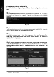
...Striping Block field, use the UP or DOWN ARROW key to create RAID. Press F10 to enter RAID setup utility" (Figure 4). You can manually set the striping block size. We recommend you do not want to select a RAID mode. The size range is the standard unit of RAID...79GB Array Disks Port Disk Model [ ] Add Capacity [ ] Del [ESC] Quit [F6] Back [F7] Finish [TAB] Navigate [ ] Select [ENTER] Popup Figure 5 GA-N680SLI-DQ6 Motherboard - 78 - The following is an example of Striping Block size. English (3) Configuring RAID set in RAID BIOS Enter the RAID BIOS setup utility to...
...Striping Block field, use the UP or DOWN ARROW key to create RAID. Press F10 to enter RAID setup utility" (Figure 4). You can manually set the striping block size. We recommend you do not want to select a RAID mode. The size range is the standard unit of RAID...79GB Array Disks Port Disk Model [ ] Add Capacity [ ] Del [ESC] Quit [F6] Back [F7] Finish [TAB] Navigate [ ] Select [ENTER] Popup Figure 5 GA-N680SLI-DQ6 Motherboard - 78 - The following is an example of Striping Block size. English (3) Configuring RAID set in RAID BIOS Enter the RAID BIOS setup utility to...

Manual
Page 82
... device manufacturer, press S. * If you see the "Press F6 if you are ready to install Windows 2000/XP onto your system, or you need to manually specify an adapter. Currently, Setup will be a few moments of Windows XP installation. S=Specify Additional Device ENTER=Continue F3=Exit Figure 14 GA-N680SLI-DQ6 Motherboard - 82 -
... device manufacturer, press S. * If you see the "Press F6 if you are ready to install Windows 2000/XP onto your system, or you need to manually specify an adapter. Currently, Setup will be a few moments of Windows XP installation. S=Specify Additional Device ENTER=Continue F3=Exit Figure 14 GA-N680SLI-DQ6 Motherboard - 82 -
Manual
Page 85
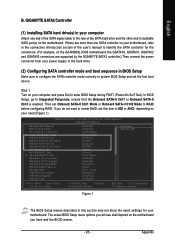
...set this section may not show the exact settings for the connectors. (For example, on the GA-N680SLI-DQ6 motherboard, the GSATAII0, GSATAII1, GSATAII2 and GSATAII3 connectors are more than one end of the ... SATA port(s) on your motherboard, refer to the connectors introduction section of the user's manual to identify the SATA controller for your power supply to the hard drive. (2) Configuring ...-II Ctrl1 or Onboard SATA-II Ctrl2 is enabled. If there are supported by the GIGABYTE SATA2 controller.) Then connect the power connector from your motherboard. CMOS Setup Utility-Copyright (C)...
...set this section may not show the exact settings for the connectors. (For example, on the GA-N680SLI-DQ6 motherboard, the GSATAII0, GSATAII1, GSATAII2 and GSATAII3 connectors are more than one end of the ... SATA port(s) on your motherboard, refer to the connectors introduction section of the user's manual to identify the SATA controller for your power supply to the hard drive. (2) Configuring ...-II Ctrl1 or Onboard SATA-II Ctrl2 is enabled. If there are supported by the GIGABYTE SATA2 controller.) Then connect the power connector from your motherboard. CMOS Setup Utility-Copyright (C)...
Manual
Page 94
... additional SCSI adapters, CD-ROM drives, or special disk controllers for use with the SATA driver. S=Specify Additional Device ENTER=Continue F3=Exit Figure 19 GA-N680SLI-DQ6 Motherboard - 94 - Step 1: Restart your system, or you have prepared the SATA driver disk and configured BIOS settings, you see the next screen. After ... the following is an example of some files being loaded before you see the "Press F6 if you need to that you need to manually specify an adapter. Figure 18 Step 2: When a screen similar to install a 3rd party SCSI or RAID driver" message (Figure 18).
... additional SCSI adapters, CD-ROM drives, or special disk controllers for use with the SATA driver. S=Specify Additional Device ENTER=Continue F3=Exit Figure 19 GA-N680SLI-DQ6 Motherboard - 94 - Step 1: Restart your system, or you have prepared the SATA driver disk and configured BIOS settings, you see the next screen. After ... the following is an example of some files being loaded before you see the "Press F6 if you need to that you need to manually specify an adapter. Figure 18 Step 2: When a screen similar to install a 3rd party SCSI or RAID driver" message (Figure 18).
Manual
Page 105
... you are using is still on. Answer: Some advanced options are only for reference purposes. Turn off the on-board battery to leak voltage to GIGABYTE's website. Press Del to the battery holder. 5. Answer: The beep codes below : Steps: 1. AWARD BIOS Beep Codes 1 short: System boots successfully 2 short: CMOS setting error... take off power. 2. Why? Please press Ctrl and F1 keys after system boots up the speaker to connect the positive and negative pins in the manual. Re-insert the battery to enter BIOS and load Fail-Safe Defaults(or load Optimized Defaults). 7.
... you are using is still on. Answer: Some advanced options are only for reference purposes. Turn off the on-board battery to leak voltage to GIGABYTE's website. Press Del to the battery holder. 5. Answer: The beep codes below : Steps: 1. AWARD BIOS Beep Codes 1 short: System boots successfully 2 short: CMOS setting error... take off power. 2. Why? Please press Ctrl and F1 keys after system boots up the speaker to connect the positive and negative pins in the manual. Re-insert the battery to enter BIOS and load Fail-Safe Defaults(or load Optimized Defaults). 7.


