Manual
Page 1
GA-N680SLI-DQ6 Intel® CoreTM 2 Extreme quad-core / CoreTM 2 Quad / Intel® CoreTM 2 Extreme dual-core / CoreTM 2 Duo / Intel® Pentium® Processor Extreme Edition / Intel® Pentium® D / Pentium® 4 LGA775 Processor Motherboard User's Manual Rev. 2001 12ME-N680DQ6-2001R * The WEEE marking on the product indicates this product must not be disposed...
GA-N680SLI-DQ6 Intel® CoreTM 2 Extreme quad-core / CoreTM 2 Quad / Intel® CoreTM 2 Extreme dual-core / CoreTM 2 Duo / Intel® Pentium® Processor Extreme Edition / Intel® Pentium® D / Pentium® 4 LGA775 Processor Motherboard User's Manual Rev. 2001 12ME-N680DQ6-2001R * The WEEE marking on the product indicates this product must not be disposed...
Manual
Page 4
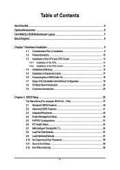
Table of Contents ItemChecklist ...6 OptionalAccessories ...6 GA-N680SLI-DQ6 Motherboard Layout 7 Block Diagram ...8 Chapter 1 Hardware Installation 9 1-1 Considerations Prior to Installation 9 1-2 Feature Summary 10 1-3 Installation of the CPU and CPU Cooler 13 1-3-1 Installation of the CPU ...
Table of Contents ItemChecklist ...6 OptionalAccessories ...6 GA-N680SLI-DQ6 Motherboard Layout 7 Block Diagram ...8 Chapter 1 Hardware Installation 9 1-1 Considerations Prior to Installation 9 1-2 Feature Summary 10 1-3 Installation of the CPU and CPU Cooler 13 1-3-1 Installation of the CPU ...

Manual
Page 9
... the product, please consult a certified computer technician. Hardware Installation To prevent damage to the motherboard, please do not remove the stickers on top of the motherboard or any metal leads or connectors. 3. Product determined to improper installation. 4. English Chapter ...Prior to wear an electrostatic discharge (ESD) cuff when handling electronic components (CPU, RAM). 4. Damage due to be an unofficial Gigabyte product. - 9 - Installation Notices 1. These stickers are connected. 4. Damage due to installation, please do not allow screws to...
... the product, please consult a certified computer technician. Hardware Installation To prevent damage to the motherboard, please do not remove the stickers on top of the motherboard or any metal leads or connectors. 3. Product determined to improper installation. 4. English Chapter ...Prior to wear an electrostatic discharge (ESD) cuff when handling electronic components (CPU, RAM). 4. Damage due to be an unofficial Gigabyte product. - 9 - Installation Notices 1. These stickers are connected. 4. Damage due to installation, please do not allow screws to...
Manual
Page 10
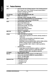
Supports data RAID 0, RAID 1 and JBOD for Serial ATA Š GIGABYTE SATA2 x 2 Controller - 4 SATA 3Gb/s connectors (GSATAII1-0, GSATAII1-1, GSATAII2-0, GSATAII2-1), allowing connection of 4 SATA 3Gb/s devices - TSB43AB23 chip Š 3 IEEE 1394a ports Š...; Supports ECC type DRAM Š 2 PCI Express x16 slots Š 1 PCI Express x8 slot Š 1 PCI Express x1 slot Š 3 PCI slots GA-N680SLI-DQ6 Motherboard - 10 - English 1-2 Feature Summary CPU Front Side Bus Chipset LAN Audio IEEE 1394 Storage O.S Support Memory Expanstion Slots Š LGA775 for Intel® CoreTM 2 ...
Supports data RAID 0, RAID 1 and JBOD for Serial ATA Š GIGABYTE SATA2 x 2 Controller - 4 SATA 3Gb/s connectors (GSATAII1-0, GSATAII1-1, GSATAII2-0, GSATAII2-1), allowing connection of 4 SATA 3Gb/s devices - TSB43AB23 chip Š 3 IEEE 1394a ports Š...; Supports ECC type DRAM Š 2 PCI Express x16 slots Š 1 PCI Express x8 slot Š 1 PCI Express x1 slot Š 3 PCI slots GA-N680SLI-DQ6 Motherboard - 10 - English 1-2 Feature Summary CPU Front Side Bus Chipset LAN Audio IEEE 1394 Storage O.S Support Memory Expanstion Slots Š LGA775 for Intel® CoreTM 2 ...
Manual
Page 12
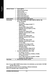
... at 0.05V (Adjustable range from 0.05V to 150 MHz - PCI Express x16 Clock: Allows 1 MHz increment from 100 MHz to 0.55V) - GA-N680SLI-DQ6 Motherboard - 12 - FSB Voltage : Adjustable FSB voltage at 0.05V (Adjustable range from 0.05V to 0.775V) - DDRII Voltage : Adjustable DDRII voltage at...24.4cm (Note 1) To use a DDR II 800/667 memory module on the motherboard, you must install a 1333/1066/ 800 MHz FSB processor. (Note 2) EasyTune functions may vary depending on different motherboards. (Note 3) The adjustable range is dependent on CPUs. English Additional Features Š...
... at 0.05V (Adjustable range from 0.05V to 150 MHz - PCI Express x16 Clock: Allows 1 MHz increment from 100 MHz to 0.55V) - GA-N680SLI-DQ6 Motherboard - 12 - FSB Voltage : Adjustable FSB voltage at 0.05V (Adjustable range from 0.05V to 0.775V) - DDRII Voltage : Adjustable DDRII voltage at...24.4cm (Note 1) To use a DDR II 800/667 memory module on the motherboard, you must install a 1333/1066/ 800 MHz FSB processor. (Note 2) EasyTune functions may vary depending on different motherboards. (Note 3) The adjustable range is dependent on CPUs. English Additional Features Š...
Manual
Page 13
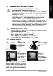
.... BIOS: A BIOS that supports HT Technology - Fig. 3 Notice the small gold colored triangle located on the CPU socket. Avoid twisting or bending motions that the motherboard supports the CPU. 2. English 1-3 Installation of the CPU and CPU Cooler Before installing the CPU, please comply with the following platform components: - Please make sure...
.... BIOS: A BIOS that supports HT Technology - Fig. 3 Notice the small gold colored triangle located on the CPU socket. Avoid twisting or bending motions that the motherboard supports the CPU. 2. English 1-3 Installation of the CPU and CPU Cooler Before installing the CPU, please comply with the following platform components: - Please make sure...
Manual
Page 14
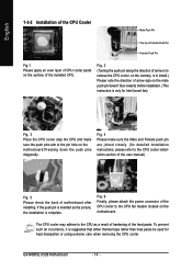
... CPU cooler may adhere to the CPU cooler installation section of the user manual) Fig. 5 Please check the back of the heat paste. GA-N680SLI-DQ6 Motherboard - 14 - If the push pin is inserted as the picture, the installation is suggested that either thermal tape rather than heat paste be used... for detailed installation instructions, please refer to the CPU as a result of hardening of motherboard after installing. Fig. 4 Please make sure the push pins aim to the CPU fan header located on the surface of the installed CPU....
... CPU cooler may adhere to the CPU cooler installation section of the user manual) Fig. 5 Please check the back of the heat paste. GA-N680SLI-DQ6 Motherboard - 14 - If the push pin is inserted as the picture, the installation is suggested that either thermal tape rather than heat paste be used... for detailed installation instructions, please refer to the CPU as a result of hardening of motherboard after installing. Fig. 4 Please make sure the push pins aim to the CPU fan header located on the surface of the installed CPU....

Manual
Page 15
... the memory modules, please comply with each slot. English 1-4 Installation of the DIMM sockets to lock the DIMM module. It is supported by the motherboard. The motherboard supports DDRII memory modules, whereby BIOS will automatically detect memory capacity and specifications. Reverse the installation steps when you are designed so that memory of...
... the memory modules, please comply with each slot. English 1-4 Installation of the DIMM sockets to lock the DIMM module. It is supported by the motherboard. The motherboard supports DDRII memory modules, whereby BIOS will automatically detect memory capacity and specifications. Reverse the installation steps when you are designed so that memory of...
Manual
Page 16
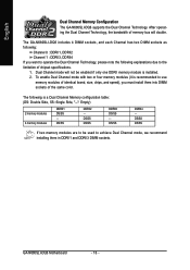
... or four memory modules (it is recommended to operate the Dual Channel Technology, please note the following is installed. 2. DS/SS DDRII4 - The GA-N680SLI-DQ6 includes 4 DIMM sockets, and each Channel has two DIMM sockets as following: Channel 0 : DDRII1, DDRII2 Channel 1 : DDRII3, DDRII4 If you...memory bus will double. DS/SS DS/SS DDRII3 DS/SS - After operating the Dual Channel Technology, the bandwidth of the same color. GA-N680SLI-DQ6 Motherboard - 16 - Dual Channel mode will not be used to be enabled if only one DDRII memory module is a Dual Channel Memory configuration...
... or four memory modules (it is recommended to operate the Dual Channel Technology, please note the following is installed. 2. DS/SS DDRII4 - The GA-N680SLI-DQ6 includes 4 DIMM sockets, and each Channel has two DIMM sockets as following: Channel 0 : DDRII1, DDRII2 Channel 1 : DDRII3, DDRII4 If you...memory bus will double. DS/SS DS/SS DDRII3 DS/SS - After operating the Dual Channel Technology, the bandwidth of the same color. GA-N680SLI-DQ6 Motherboard - 16 - Dual Channel mode will not be used to be enabled if only one DDRII memory module is a Dual Channel Memory configuration...

Manual
Page 17
...the expansion card firmly into the expansion slot in the operating system. Replace the screw to the onboard PCI Express x16 slot. The motherboard includes a PCIE_12V power connector, which provides extra power to secure the slot bracket of Expansion Cards To install your computer's chassis ...cover. 7. English 1-5 Installation of the expansion card. 6. Replace your expansion card, follow the steps below. 1. Install related driver in the motherboard. 4. To remove the VGA card: When you can press the latch as the picture to the left shows to this connector. - 17 -...
...the expansion card firmly into the expansion slot in the operating system. Replace the screw to the onboard PCI Express x16 slot. The motherboard includes a PCIE_12V power connector, which provides extra power to secure the slot bracket of Expansion Cards To install your computer's chassis ...cover. 7. English 1-5 Installation of the expansion card. 6. Replace your expansion card, follow the steps below. 1. Install related driver in the motherboard. 4. To remove the VGA card: When you can press the latch as the picture to the left shows to this connector. - 17 -...
Manual
Page 18
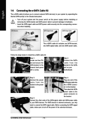
... signal cable, and one SATA power cable. tor on your motherboard. English 1-6 Connecting the e-SATA Cable Kit The e-SATA cable kit allows you only need to your SATA devices. Then attach the SATA power cable to the SATA port on the bracket. GA-N680SLI-DQ6 Motherboard - 18 - Step 2: Connect the SATA cable from the SATA...
... signal cable, and one SATA power cable. tor on your motherboard. English 1-6 Connecting the e-SATA Cable Kit The e-SATA cable kit allows you only need to your SATA devices. Then attach the SATA power cable to the SATA port on the bracket. GA-N680SLI-DQ6 Motherboard - 18 - Step 2: Connect the SATA cable from the SATA...

Manual
Page 19
... and PCIE_16_2 slots. (It is recommended to your overall system configurations. For example: GIGABYTE GV-NX76T256D-RH). Please refer to the table below to set up a single graphics card system, we recommend installing the graphics card on the GA-N680SLI-DQ6 motherboard. If you want to check recommended power for different systems. System configuration Processors...
... and PCIE_16_2 slots. (It is recommended to your overall system configurations. For example: GIGABYTE GV-NX76T256D-RH). Please refer to the table below to set up a single graphics card system, we recommend installing the graphics card on the GA-N680SLI-DQ6 motherboard. If you want to check recommended power for different systems. System configuration Processors...
Manual
Page 20
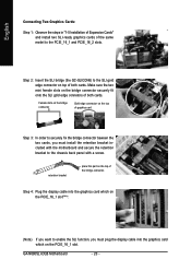
...graphics card Step 3: In order to securely fix the bridge connector beween the two cards, you must install the retention bracket included with a screw. GA-N680SLI-DQ6 Motherboard - 20 - Step 4: Plug the display cable into the graphics card which on the PCIE_16_1 slot(Note). (Note) If you want to the ...chassis back panel with the motherboard and secure the retention bracket to enable the SLI function, you must plug the display cable into the graphics card which on the PCIE_16_1...
...graphics card Step 3: In order to securely fix the bridge connector beween the two cards, you must install the retention bracket included with a screw. GA-N680SLI-DQ6 Motherboard - 20 - Step 4: Plug the display cable into the graphics card which on the PCIE_16_1 slot(Note). (Note) If you want to the ...chassis back panel with the motherboard and secure the retention bracket to enable the SLI function, you must plug the display cable into the graphics card which on the PCIE_16_1...
Manual
Page 22
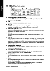
... (purple). Surround Speaker Out (Rear Speaker Out) The default Surround Speaker Out (Rear Speaker Out) jack. Devices like high speed, high bandwidth and hot plug. GA-N680SLI-DQ6 Motherboard - 22 - English 1-8 I/O Back Panel Introduction PS/2 Keyboard and PS/2 Mouse Connector To install a PS/2 port keyboard and mouse, plug the mouse to the upper port...
... (purple). Surround Speaker Out (Rear Speaker Out) The default Surround Speaker Out (Rear Speaker Out) jack. Devices like high speed, high bandwidth and hot plug. GA-N680SLI-DQ6 Motherboard - 22 - English 1-8 I/O Back Panel Introduction PS/2 Keyboard and PS/2 Mouse Connector To install a PS/2 port keyboard and mouse, plug the mouse to the upper port...
Manual
Page 24
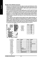
...do not remove it. 8 4 5 1 ATX_12V_2X Pin No. 1 2 3 4 5 6 7 8 Definition GND GND GND GND +12V +12V +12V +12V 12 24 1 13 ATX GA-N680SLI-DQ6 Motherboard Pin No. 1 2 3 4 5 6 7 8 9 10 11 12 Definition 3.3V 3.3V GND +5V GND +5V GND Power Good 5V SB(stand by processor manufacturer when using Intel&#... enough stable power to all components and devices are properly installed. Please use a power supply that all the components on the motherboard. Important Use of the power connector, the power supply can withstand high power consumption be used that does not provide the required...
...do not remove it. 8 4 5 1 ATX_12V_2X Pin No. 1 2 3 4 5 6 7 8 Definition GND GND GND GND +12V +12V +12V +12V 12 24 1 13 ATX GA-N680SLI-DQ6 Motherboard Pin No. 1 2 3 4 5 6 7 8 9 10 11 12 Definition 3.3V 3.3V GND +5V GND +5V GND Power Good 5V SB(stand by processor manufacturer when using Intel&#... enough stable power to all components and devices are properly installed. Please use a power supply that all the components on the motherboard. Important Use of the power connector, the power supply can withstand high power consumption be used that does not provide the required...
Manual
Page 26
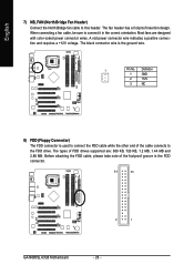
... ground wire. 1 Pin No. English 7) NB_FAN (North Bridge Fan Header) Connect the North Bridge fan cable to connect it in the FDD connector. 34 33 2 1 GA-N680SLI-DQ6 Motherboard - 26 - The black connector wire is used to connect the FDD cable while the other end of the cable connects to the FDD drive. Most...
... ground wire. 1 Pin No. English 7) NB_FAN (North Bridge Fan Header) Connect the North Bridge fan cable to connect it in the FDD connector. 34 33 2 1 GA-N680SLI-DQ6 Motherboard - 26 - The black connector wire is used to connect the FDD cable while the other end of the cable connects to the FDD drive. Most...
Manual
Page 28
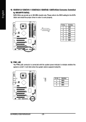
GA-N680SLI-DQ6 Motherboard - 28 - English 11) GSATAII1-0 / GSATAII1-1 / GSATAII2-0 / GSATAII2-1 (SATA 3Gb/s Connector, Controlled by GIGABYTE SATA2) SATA 3Gb/s can provide up to indicate whether the system is connected with the system power indicator to 300 MB/s transfer rate. It will ...
GA-N680SLI-DQ6 Motherboard - 28 - English 11) GSATAII1-0 / GSATAII1-1 / GSATAII2-0 / GSATAII2-1 (SATA 3Gb/s Connector, Controlled by GIGABYTE SATA2) SATA 3Gb/s can provide up to indicate whether the system is connected with the system power indicator to 300 MB/s transfer rate. It will ...
Manual
Page 30
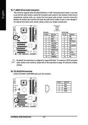
Definition 1 CD-L 2 GND 3 GND 4 CD-R 1 GA-N680SLI-DQ6 Motherboard - 30 - For optional front panel audio module, please contact your chassis manufacturer. 10 9 HD Audio: Pin No. 1 2 3 4 5 6 7 8 9 10 2 1 Definition MIC2_L GND MIC2_R -ACZ_DET LINE2_R FSENSE1 ...
Definition 1 CD-L 2 GND 3 GND 4 CD-R 1 GA-N680SLI-DQ6 Motherboard - 30 - For optional front panel audio module, please contact your chassis manufacturer. 10 9 HD Audio: Pin No. 1 2 3 4 5 6 7 8 9 10 2 1 Definition MIC2_L GND MIC2_R -ACZ_DET LINE2_R FSENSE1 ...
Manual
Page 32
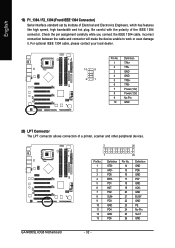
... 16 17 18 19 20 21 22 23 24 25 26 Definition GND PD6 GND PD7 GND ACKGND BUSY GND PE No Pin SLCT GND GA-N680SLI-DQ6 Motherboard - 32 - English 19) F1_1394 / F2_1394 (Front IEEE 1394 Connector) Serial interface standard set by Institute of Electrical and Electronics Engineers, which has features like high...
... 16 17 18 19 20 21 22 23 24 25 26 Definition GND PD6 GND PD7 GND ACKGND BUSY GND PE No Pin SLCT GND GA-N680SLI-DQ6 Motherboard - 32 - English 19) F1_1394 / F2_1394 (Front IEEE 1394 Connector) Serial interface standard set by Institute of Electrical and Electronics Engineers, which has features like high...
Manual
Page 34
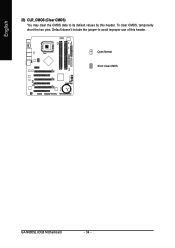
Open: Normal Short: Clear CMOS GA-N680SLI-DQ6 Motherboard - 34 - English 23) CLR_CMOS (Clear CMOS) You may clear the CMOS data to avoid improper use of this header. To clear CMOS, temporarily short the two pins. Default doesn't include the jumper to its default values by this header.
Open: Normal Short: Clear CMOS GA-N680SLI-DQ6 Motherboard - 34 - English 23) CLR_CMOS (Clear CMOS) You may clear the CMOS data to avoid improper use of this header. To clear CMOS, temporarily short the two pins. Default doesn't include the jumper to its default values by this header.


