
Manual
Page 1
GA-MA790GP-UD3H AM2+/AM2 socket motherboard for AMD PhenomTM II X4 processor/AMD PhenomTM II X3 processor/ AMD PhenomTM FX processor/AMD PhenomTM X4 processor/ AMD PhenomTM X3 processor/AMD AthlonTM X2 processor/ AMD AthlonTM processor/AMD SempronTM X2 processor/ AMD SempronTM processor User's Manual Rev. 1001 12ME-MA79PU3-1001R
GA-MA790GP-UD3H AM2+/AM2 socket motherboard for AMD PhenomTM II X4 processor/AMD PhenomTM II X3 processor/ AMD PhenomTM FX processor/AMD PhenomTM X4 processor/ AMD PhenomTM X3 processor/AMD AthlonTM X2 processor/ AMD AthlonTM processor/AMD SempronTM X2 processor/ AMD SempronTM processor User's Manual Rev. 1001 12ME-MA79PU3-1001R
Manual
Page 3
..., drivers, or when looking for technical information. For product-related information, check on our website at: http://www.gigabyte.com.tw Identifying Your Motherboard Revision The revision number on our website. Check your motherboard looks like this manual may be reproduced, copied, translated, transmitted, or published in this manual may be made by...
..., drivers, or when looking for technical information. For product-related information, check on our website at: http://www.gigabyte.com.tw Identifying Your Motherboard Revision The revision number on our website. Check your motherboard looks like this manual may be reproduced, copied, translated, transmitted, or published in this manual may be made by...
Manual
Page 4
Table of Contents Box Contents ...6 OptionalItems...6 GA-MA790GP-UD3H Motherboard Layout 7 Block Diagram...8 Chapter 1 Hardware Installation 9 1-1 Installation Precautions 9 1-2 Product Specifications 10 1-3 Installing the CPU and CPU Cooler 13 1-3-1 Installing the CPU 13 1-3-2 Installing the CPU ...
Table of Contents Box Contents ...6 OptionalItems...6 GA-MA790GP-UD3H Motherboard Layout 7 Block Diagram...8 Chapter 1 Hardware Installation 9 1-1 Installation Precautions 9 1-2 Product Specifications 10 1-3 Installing the CPU and CPU Cooler 13 1-3-1 Installing the CPU 13 1-3-2 Installing the CPU ...
Manual
Page 6
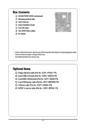
... SATA power cable (Part No. 12CF1-2SERPW-0*R) COM port cable (Part No. 12CF1-1CM001-3*R) S/PDIF in and out cable (Part No. 12CR1-1SPINO-1*R) - 6 - Box Contents GA-MA790GP-UD3H motherboard Motherboard driver disk User's Manual Quick Installation Guide One IDE cable Two SATA 3Gb/s cables I/O Shield • The box contents above are subject to change without...
... SATA power cable (Part No. 12CF1-2SERPW-0*R) COM port cable (Part No. 12CF1-1CM001-3*R) S/PDIF in and out cable (Part No. 12CR1-1SPINO-1*R) - 6 - Box Contents GA-MA790GP-UD3H motherboard Motherboard driver disk User's Manual Quick Installation Guide One IDE cable Two SATA 3Gb/s cables I/O Shield • The box contents above are subject to change without...
Manual
Page 7
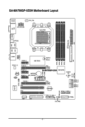
GA-MA790GP-UD3H Motherboard Layout VGA KB_MS CPU_FAN ATX_12V_2X4 Socket AM2 DVI HDMI OPTICAL PWR_FAN ATX 1394 USB LAN USB F_AUDIO AUDIO PCIEX1_1 AMD 790GX SidePort Memory IDE DDR2_1 DDR2_2 DDR2_3 DDR2_4 RTL8111C PCIEX16_1 CD_IN CODEC PCIEX1_2 BATTERY PCIEX1_3 CLR_CMOS PCIEX8_1 PCI1 IT8718 SPDIF_IO PCI2 COM FDD F_USB1 F_USB2 F_USB4 F_USB3 SYS_FAN1 GA-MA790GP-UD3H AMD SB750 M_BIOS B_ BIOS TSB43AB23 SATA2_4 SATA2_5 SATA2_2 SATA2_3 SATA2_0 SATA2_1 PWR_LED F_1394_1F_1394_2 CI SYS_FAN2 F_PANEL - 7 -
GA-MA790GP-UD3H Motherboard Layout VGA KB_MS CPU_FAN ATX_12V_2X4 Socket AM2 DVI HDMI OPTICAL PWR_FAN ATX 1394 USB LAN USB F_AUDIO AUDIO PCIEX1_1 AMD 790GX SidePort Memory IDE DDR2_1 DDR2_2 DDR2_3 DDR2_4 RTL8111C PCIEX16_1 CD_IN CODEC PCIEX1_2 BATTERY PCIEX1_3 CLR_CMOS PCIEX8_1 PCI1 IT8718 SPDIF_IO PCI2 COM FDD F_USB1 F_USB2 F_USB4 F_USB3 SYS_FAN1 GA-MA790GP-UD3H AMD SB750 M_BIOS B_ BIOS TSB43AB23 SATA2_4 SATA2_5 SATA2_2 SATA2_3 SATA2_0 SATA2_1 PWR_LED F_1394_1F_1394_2 CI SYS_FAN2 F_PANEL - 7 -
Manual
Page 9
... within an electrostatic shielding container. • Before unplugging the power supply cable from the power outlet before installing or removing the motherboard or other hardware components. • When connecting hardware components to the internal connectors on the computer power during the installation process... system on an uneven surface. • Do not place the computer system in a high-temperature environment. • Turning on the motherboard, make sure the power supply voltage has been set according to the local voltage standard. • Before using the product, please verify...
... within an electrostatic shielding container. • Before unplugging the power supply cable from the power outlet before installing or removing the motherboard or other hardware components. • When connecting hardware components to the internal connectors on the computer power during the installation process... system on an uneven surface. • Do not place the computer system in a high-temperature environment. • Turning on the motherboard, make sure the power supply voltage has been set according to the local voltage standard. • Before using the product, please verify...
Manual
Page 10
...PhenomTM X3 processor/AMD AthlonTM X2 processor/ AMD AthlonTM processor/AMD SempronTM X2 processor/ AMD SempronTM processor (Go to GIGABYTE's website for the latest CPU support list.) 5200 MT/s North Bridge: AMD 790GX South Bridge: AMD SB750 4...GIGABYTE's website for the latest memory support list.) 128 MB DDR3 SidePort memory Realtek ALC888 codec High Definition Audio 2/4/5.1/7.1-channel Support for S/PDIF In/Out Support for SATA RAID 0, RAID 1, RAID 5, RAID 10, and JBOD iTE IT8718 chip: - 1 x floppy disk drive connector supporting up to the internal USB headers) GA-MA790GP-UD3H Motherboard...
...PhenomTM X3 processor/AMD AthlonTM X2 processor/ AMD AthlonTM processor/AMD SempronTM X2 processor/ AMD SempronTM processor (Go to GIGABYTE's website for the latest CPU support list.) 5200 MT/s North Bridge: AMD 790GX South Bridge: AMD SB750 4...GIGABYTE's website for the latest memory support list.) 128 MB DDR3 SidePort memory Realtek ALC888 codec High Definition Audio 2/4/5.1/7.1-channel Support for S/PDIF In/Out Support for SATA RAID 0, RAID 1, RAID 5, RAID 10, and JBOD iTE IT8718 chip: - 1 x floppy disk drive connector supporting up to the internal USB headers) GA-MA790GP-UD3H Motherboard...
Manual
Page 12
GA-MA790GP-UD3H Motherboard - 12 - The PCIEX8_1 slot shares bandwidth with a PCI Express graphics card, the PCIEX16_1 slot will depend on the CPU being used. (Note 3) For optimum performance, ... only one PCI Express graphics card is supported will operate at up to x8 mode. (Note 4) The DVI-D port does not support D-Sub connection by motherboard model. (Note 7) Due to the hardware limitation, you install. (Note 6) Available functions in EasyTune may differ by adapter. (Note 5) Whether the CPU/system fan speed...
GA-MA790GP-UD3H Motherboard - 12 - The PCIEX8_1 slot shares bandwidth with a PCI Express graphics card, the PCIEX16_1 slot will depend on the CPU being used. (Note 3) For optimum performance, ... only one PCI Express graphics card is supported will operate at up to x8 mode. (Note 4) The DVI-D port does not support D-Sub connection by motherboard model. (Note 7) Due to the hardware limitation, you install. (Note 6) Available functions in EasyTune may differ by adapter. (Note 5) Whether the CPU/system fan speed...
Manual
Page 13
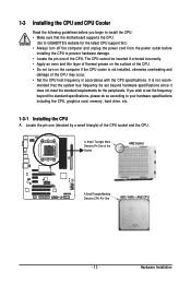
mended that the motherboard supports the CPU. (Go to GIGABYTE's website for the peripherals. Locate the pin one of the CPU. Hardware Installation 1-3 Installing the CPU and CPU Cooler Read the following guidelines before installing ...
mended that the motherboard supports the CPU. (Go to GIGABYTE's website for the peripherals. Locate the pin one of the CPU. Hardware Installation 1-3 Installing the CPU and CPU Cooler Read the following guidelines before installing ...
Manual
Page 14
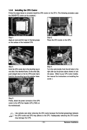
... triangle marking) with the triangle mark on the middle of the CPU, lowering the locking lever and latching it into the motherboard CPU socket. Follow the steps below to the CPU. Adjust the CPU orientation if this occurs. GA-MA790GP-UD3H Motherboard - 14 - B. Make sure that the CPU pins fit perfectly into the CPU socket.
... triangle marking) with the triangle mark on the middle of the CPU, lowering the locking lever and latching it into the motherboard CPU socket. Follow the steps below to the CPU. Adjust the CPU orientation if this occurs. GA-MA790GP-UD3H Motherboard - 14 - B. Make sure that the CPU pins fit perfectly into the CPU socket.
Manual
Page 15
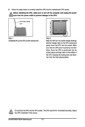
...installed CPU. On the other side, push straight down on the the CPU cooler clip to hook it to the mounting lug on the motherboard. Inadequately removing the CPU cooler may adhere to the CPU. Use extreme care when removing the CPU cooler because the thermal grease/tape ... - 15 - 1-3-2 Installing the CPU Cooler Follow the steps below to correctly install the CPU cooler on the CPU. (The following procedure uses the GIGABYTE cooler as the picture above shows) to lock into place. (Refer to your CPU cooler installation manual for instructions on installing the cooler.) Step 5: ...
...installed CPU. On the other side, push straight down on the the CPU cooler clip to hook it to the mounting lug on the motherboard. Inadequately removing the CPU cooler may adhere to the CPU. Use extreme care when removing the CPU cooler because the thermal grease/tape ... - 15 - 1-3-2 Installing the CPU Cooler Follow the steps below to correctly install the CPU cooler on the CPU. (The following procedure uses the GIGABYTE cooler as the picture above shows) to lock into place. (Refer to your CPU cooler installation manual for instructions on installing the cooler.) Step 5: ...
Manual
Page 16
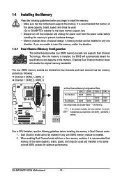
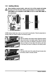
...memory bandwidth. It is recommended that memory of the same capacity, brand, speed, and chips be used . (Go to GIGABYTE's website for optimum performance. GA-MA790GP-UD3H Motherboard - 16 - If you are divided into two channels and each channel has two memory sockets as following: Channel 0: ... the memory, switch the direction. 1-4-1 Dual Channel Memory Configuration This motherboard provides four DDR2 memory sockets and supports Dual Channel Technology. After the memory is recommended that the motherboard supports the memory. Dual Channel mode cannot be installed, it is ...
...memory bandwidth. It is recommended that memory of the same capacity, brand, speed, and chips be used . (Go to GIGABYTE's website for optimum performance. GA-MA790GP-UD3H Motherboard - 16 - If you are divided into two channels and each channel has two memory sockets as following: Channel 0: ... the memory, switch the direction. 1-4-1 Dual Channel Memory Configuration This motherboard provides four DDR2 memory sockets and supports Dual Channel Technology. After the memory is recommended that the motherboard supports the memory. Dual Channel mode cannot be installed, it is ...
Manual
Page 17
... on the socket. Spread the retaining clips at both ends of the socket will snap into the memory socket. Place the memory module on this motherboard. Hardware Installation Step 2: The clips at both ends of the memory socket. Step 1: Note the orientation of the memory, push down on the memory and...
... on the socket. Spread the retaining clips at both ends of the socket will snap into the memory socket. Place the memory module on this motherboard. Hardware Installation Step 2: The clips at both ends of the memory socket. Step 1: Note the orientation of the memory, push down on the memory and...
Manual
Page 18
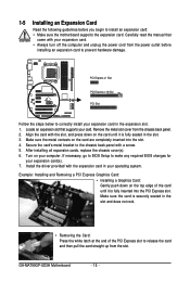
... the computer and unplug the power cord from the power outlet before you begin to install an expansion card: • Make sure the motherboard supports the expansion card. GA-MA790GP-UD3H Motherboard - 18 - Carefully read the manual that supports your operating system. Install the driver provided with your expansion card in the slot and does...
... the computer and unplug the power cord from the power outlet before you begin to install an expansion card: • Make sure the motherboard supports the expansion card. GA-MA790GP-UD3H Motherboard - 18 - Carefully read the manual that supports your operating system. Install the driver provided with your expansion card in the slot and does...
Manual
Page 19
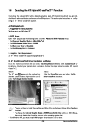
...the CrossFire function in the operating system first. * For Windows XP, you begin-1. ATI Hybrid CrossFireX Driver Installation and Setup Insert the motherboard driver disk and select Installing Chipset Drivers. 1-6 Enabling the ATI Hybrid CrossFireXTM Function Combining the onboard GPU with a discrete graphics card, ... the CrossFire menu and select the Enable CrossFire checkbox. • You do not have to install the graphics card driver if the motherboard chipset driver has been installed. • To change the Internal Graphic Mode or UMA Frame Buffer Size setting in the system tray ...
...the CrossFire function in the operating system first. * For Windows XP, you begin-1. ATI Hybrid CrossFireX Driver Installation and Setup Insert the motherboard driver disk and select Installing Chipset Drivers. 1-6 Enabling the ATI Hybrid CrossFireXTM Function Combining the onboard GPU with a discrete graphics card, ... the CrossFire menu and select the Enable CrossFire checkbox. • You do not have to install the graphics card driver if the motherboard chipset driver has been installed. • To change the Internal Graphic Mode or UMA Frame Buffer Size setting in the system tray ...
Manual
Page 20
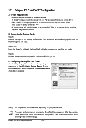
... (Note) - Step 2: (Note) Insert the CrossFire bridges in the CrossFireX gold edge connectors on the PCIEX16_1 slot. C. Procedure and driver screen for the power requirement) B. GA-MA790GP-UD3H Motherboard - 20 - Two CrossFireX-ready graphics cards of ATI CrossFireXTM Configuration A. Refer to the ATI Catalyst Control Center. Configuring the Graphics Card Driver After installing the...
... (Note) - Step 2: (Note) Insert the CrossFire bridges in the CrossFireX gold edge connectors on the PCIEX16_1 slot. C. Procedure and driver screen for the power requirement) B. GA-MA790GP-UD3H Motherboard - 20 - Two CrossFireX-ready graphics cards of ATI CrossFireXTM Configuration A. Refer to the ATI Catalyst Control Center. Configuring the Graphics Card Driver After installing the...
Manual
Page 22
Dual Display Configurations: This motherboard provides three ports for an IEEE 1394a device. Playback of HD DVD and Blu-ray Discs: In order to get better playback quality, when playing ...-D + HDMI No HDMI + D-Sub Yes B. Use this port for more information) • Playback software: CyberLink PowerDVD 8.0 or later (Note: Please ensure Hardware Acceleration is occurring GA-MA790GP-UD3H Motherboard - 22 - Use this port for video output: DVI-D, HDMI and D-Sub. IEEE 1394a Port The IEEE 1394 port supports the IEEE 1394a specification, featuring high...
Dual Display Configurations: This motherboard provides three ports for an IEEE 1394a device. Playback of HD DVD and Blu-ray Discs: In order to get better playback quality, when playing ...-D + HDMI No HDMI + D-Sub Yes B. Use this port for more information) • Playback software: CyberLink PowerDVD 8.0 or later (Note: Please ensure Hardware Acceleration is occurring GA-MA790GP-UD3H Motherboard - 22 - Use this port for video output: DVI-D, HDMI and D-Sub. IEEE 1394a Port The IEEE 1394 port supports the IEEE 1394a specification, featuring high...
Manual
Page 23
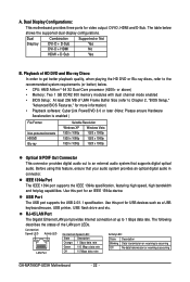
... 2/4/5.1/7.1-Channel Audio." • When removing the cable connected to a back panel connector, first remove the cable from your device and then remove it from the motherboard. • When removing the cable, pull it side to side to the default Mic in devices such as an optical drive, walkman, etc. Do not...
... 2/4/5.1/7.1-Channel Audio." • When removing the cable connected to a back panel connector, first remove the cable from your device and then remove it from the motherboard. • When removing the cable, pull it side to side to the default Mic in devices such as an optical drive, walkman, etc. Do not...

Manual
Page 24
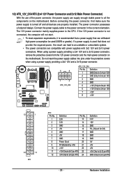
GA-MA790GP-UD3H Motherboard - 24 - 1-9 Internal Connectors 13 2 6 7 13 11 14 4 15 16 20 9 18 8 17 19 510 12 1) ATX_12V_2X4 2) ATX 3) CPU_FAN 4) SYS_FAN1 5) SYS_FAN2 6) PWR_FAN 7) IDE 8) FDD 9) SATA2_0 / 1 / 2 / 3 / 4 / 5 10) ..., make sure your devices are compliant with the connectors you wish to connect. • Before installing the devices, be sure to the connector on the motherboard. Unplug the power cord from the power outlet to prevent damage to the devices. • After installing the device and before connecting external devices: •...
GA-MA790GP-UD3H Motherboard - 24 - 1-9 Internal Connectors 13 2 6 7 13 11 14 4 15 16 20 9 18 8 17 19 510 12 1) ATX_12V_2X4 2) ATX 3) CPU_FAN 4) SYS_FAN1 5) SYS_FAN2 6) PWR_FAN 7) IDE 8) FDD 9) SATA2_0 / 1 / 2 / 3 / 4 / 5 10) ..., make sure your devices are compliant with the connectors you wish to connect. • Before installing the devices, be sure to the connector on the motherboard. Unplug the power cord from the power outlet to prevent damage to the devices. • After installing the device and before connecting external devices: •...
Manual
Page 25
... is not connected, the computer will not start. • To meet expansion requirements, it is turned off and all the components on the motherboard. Do not insert the power supply cables into pins under the protective covers when using a power supply providing a 2x4 12V and a 2x12 power... connector, remove the protective covers from the 12V power connector and the main power connector on the motherboard. 1/2) ATX_12V_2X4/ATX (2x4 12V Power Connector and 2x12 Main Power Connector) With the use of the power connector, the power supply can lead...
... is not connected, the computer will not start. • To meet expansion requirements, it is turned off and all the components on the motherboard. Do not insert the power supply cables into pins under the protective covers when using a power supply providing a 2x4 12V and a 2x12 power... connector, remove the protective covers from the 12V power connector and the main power connector on the motherboard. 1/2) ATX_12V_2X4/ATX (2x4 12V Power Connector and 2x12 Main Power Connector) With the use of the power connector, the power supply can lead...


