
Manual
Page 3
...to assist in this : "REV: X.X." Example: Check your motherboard looks like this manual may be made by any form or by GIGABYTE without GIGABYTE's prior written permission. For example, "REV: 1.0" means the revision of the motherboard is the property of the product, read the ...or download the information on/from the Support&Downloads\Motherboard\Technology Guide page on your motherboard revision before updating motherboard BIOS, drivers, or when looking for technical information. Changes to their respective owners. For product-related information, check on our website ...
...to assist in this : "REV: X.X." Example: Check your motherboard looks like this manual may be made by any form or by GIGABYTE without GIGABYTE's prior written permission. For example, "REV: 1.0" means the revision of the motherboard is the property of the product, read the ...or download the information on/from the Support&Downloads\Motherboard\Technology Guide page on your motherboard revision before updating motherboard BIOS, drivers, or when looking for technical information. Changes to their respective owners. For product-related information, check on our website ...
Manual
Page 4
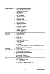
Table of Contents Box Contents ...6 OptionalItems...6 GA-MA790GP-UD3H Motherboard Layout 7 Block Diagram...8 Chapter 1 Hardware Installation 9 1-1 Installation Precautions 9 1-2 Product Specifications 10 1-3 Installing the CPU and CPU Cooler... ATI CrossFireXTM Configuration 20 1-8 Back Panel Connectors 21 1-9 Internal Connectors 24 Chapter 2 BIOS Setup 35 2-1 Startup Screen 36 2-2 The Main Menu 37 2-3 MB Intelligent Tweaker(M.I.T 39 2-4 Standard CMOS Features 44 2-5 Advanced BIOS Features 46 2-6 IntegratedPeripherals 49 2-7 Power Management Setup 52 2-8 PnP/PCI Configurations 54 ...
Table of Contents Box Contents ...6 OptionalItems...6 GA-MA790GP-UD3H Motherboard Layout 7 Block Diagram...8 Chapter 1 Hardware Installation 9 1-1 Installation Precautions 9 1-2 Product Specifications 10 1-3 Installing the CPU and CPU Cooler... ATI CrossFireXTM Configuration 20 1-8 Back Panel Connectors 21 1-9 Internal Connectors 24 Chapter 2 BIOS Setup 35 2-1 Startup Screen 36 2-2 The Main Menu 37 2-3 MB Intelligent Tweaker(M.I.T 39 2-4 Standard CMOS Features 44 2-5 Advanced BIOS Features 46 2-6 IntegratedPeripherals 49 2-7 Power Management Setup 52 2-8 PnP/PCI Configurations 54 ...

Manual
Page 5
... 62 3-3 Technical Manuals 62 3-4 Contact ...63 3-5 System ...63 3-6 Download Center 64 Chapter 4 Unique Features 65 4-1 Xpress Recovery2 65 4-2 BIOS Update Utilities 68 4-2-1 Updating the BIOS with the Q-Flash Utility 68 4-2-2 Updating the BIOS with the @BIOS Utility 71 4-3 EasyTune 6 ...72 4-4 Easy Energy Saver 73 Chapter 5 Appendix ...75 5-1 Configuring SATA Hard Drive(s 75 5-1-1 Configuring the...
... 62 3-3 Technical Manuals 62 3-4 Contact ...63 3-5 System ...63 3-6 Download Center 64 Chapter 4 Unique Features 65 4-1 Xpress Recovery2 65 4-2 BIOS Update Utilities 68 4-2-1 Updating the BIOS with the Q-Flash Utility 68 4-2-2 Updating the BIOS with the @BIOS Utility 71 4-3 EasyTune 6 ...72 4-4 Easy Energy Saver 73 Chapter 5 Appendix ...75 5-1 Configuring SATA Hard Drive(s 75 5-1-1 Configuring the...
Manual
Page 7
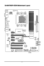
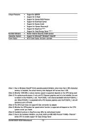
GA-MA790GP-UD3H Motherboard Layout VGA KB_MS CPU_FAN ATX_12V_2X4 Socket AM2 DVI HDMI OPTICAL PWR_FAN ATX 1394 USB LAN USB F_AUDIO AUDIO PCIEX1_1 AMD 790GX SidePort Memory IDE DDR2_1 DDR2_2 DDR2_3 DDR2_4 RTL8111C PCIEX16_1 CD_IN CODEC PCIEX1_2 BATTERY PCIEX1_3 CLR_CMOS PCIEX8_1 PCI1 IT8718 SPDIF_IO PCI2 COM FDD F_USB1 F_USB2 F_USB4 F_USB3 SYS_FAN1 GA-MA790GP-UD3H AMD SB750 M_BIOS B_ BIOS TSB43AB23 SATA2_4 SATA2_5 SATA2_2 SATA2_3 SATA2_0 SATA2_1 PWR_LED F_1394_1F_1394_2 CI SYS_FAN2 F_PANEL - 7 -
GA-MA790GP-UD3H Motherboard Layout VGA KB_MS CPU_FAN ATX_12V_2X4 Socket AM2 DVI HDMI OPTICAL PWR_FAN ATX 1394 USB LAN USB F_AUDIO AUDIO PCIEX1_1 AMD 790GX SidePort Memory IDE DDR2_1 DDR2_2 DDR2_3 DDR2_4 RTL8111C PCIEX16_1 CD_IN CODEC PCIEX1_2 BATTERY PCIEX1_3 CLR_CMOS PCIEX8_1 PCI1 IT8718 SPDIF_IO PCI2 COM FDD F_USB1 F_USB2 F_USB4 F_USB3 SYS_FAN1 GA-MA790GP-UD3H AMD SB750 M_BIOS B_ BIOS TSB43AB23 SATA2_4 SATA2_5 SATA2_2 SATA2_3 SATA2_0 SATA2_1 PWR_LED F_1394_1F_1394_2 CI SYS_FAN2 F_PANEL - 7 -
Manual
Page 8
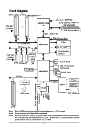
... Channel Memory x8 x16 PCI Express x16 PCIe CLK (100 MHz) PCI Express Bus x1 x1 x1 x1 RTL8111C RJ45 3 PCI Express x1 LAN Dual BIOS PCI Bus TSB43AB23 AMD 790GX GFX CLK (100 MHz) D-Sub DVI-D or HDMI (Note 2) DDR3 SidePort Memory AMD SB750 6 SATA 3Gb/s ATA-133/100/66...
... Channel Memory x8 x16 PCI Express x16 PCIe CLK (100 MHz) PCI Express Bus x1 x1 x1 x1 RTL8111C RJ45 3 PCI Express x1 LAN Dual BIOS PCI Bus TSB43AB23 AMD 790GX GFX CLK (100 MHz) D-Sub DVI-D or HDMI (Note 2) DDR3 SidePort Memory AMD SB750 6 SATA 3Gb/s ATA-133/100/66...
Manual
Page 11
... detection CPU/System/Power fan speed detection CPU overheating warning CPU/System fan fail warning CPU/System fan speed control (Note 5) BIOS 2 x 8 Mbit flash Use of licensed AWARD BIOS Support for DualBIOSTM PnP 1.0a, DMI 2.0, SM...
... detection CPU/System/Power fan speed detection CPU overheating warning CPU/System fan fail warning CPU/System fan speed control (Note 5) BIOS 2 x 8 Mbit flash Use of licensed AWARD BIOS Support for DualBIOSTM PnP 1.0a, DMI 2.0, SM...
Manual
Page 12
GA-MA790GP-UD3H Motherboard - 12 - Unique Features Bundled Software Operating System Form Factor Support for @BIOS Support for Q-Flash Support for Xpress BIOS Rescue Support for Download Center Support for Xpress Install Support for Xpress Recovery2 Support for EasyTune (Note 6) Support for Easy ...
GA-MA790GP-UD3H Motherboard - 12 - Unique Features Bundled Software Operating System Form Factor Support for @BIOS Support for Q-Flash Support for Xpress BIOS Rescue Support for Download Center Support for Xpress Install Support for Xpress Recovery2 Support for EasyTune (Note 6) Support for Easy ...
Manual
Page 16
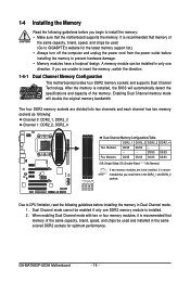
...sockets are to be installed in only one DDR2 memory module is installed, the BIOS will double the original memory bandwidth. It is recommended that the motherboard supports the... Memory Configurations Table DDR2_1 DDR2_2 DDR2_3 DDR2_4 Two Modules DS/SS DS/SS - - - - - - - - GA-MA790GP-UD3H Motherboard - 16 - 1-4 Installing the Memory Read the following guidelines before installing the memory in Dual Channel mode. 1....design. Dual Channel mode cannot be used . (Go to GIGABYTE's website for optimum performance. If you begin to install the memory: • Make sure ...
...sockets are to be installed in only one DDR2 memory module is installed, the BIOS will double the original memory bandwidth. It is recommended that the motherboard supports the... Memory Configurations Table DDR2_1 DDR2_2 DDR2_3 DDR2_4 Two Modules DS/SS DS/SS - - - - - - - - GA-MA790GP-UD3H Motherboard - 16 - 1-4 Installing the Memory Read the following guidelines before installing the memory in Dual Channel mode. 1....design. Dual Channel mode cannot be used . (Go to GIGABYTE's website for optimum performance. If you begin to install the memory: • Make sure ...
Manual
Page 18
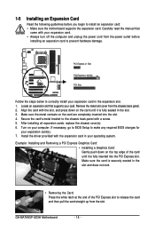
... metal contacts on the top edge of the PCI Express slot to release the card and then pull the card straight up from the slot. GA-MA790GP-UD3H Motherboard - 18 - Secure the card's metal bracket to the chassis back panel with the slot, and press down on the card are completely inserted .... 2. Locate an expansion slot that came with the expansion card in your expansion card in the slot. 3. If necessary, go to BIOS Setup to make any required BIOS changes for your computer. Turn on the card until it is fully inserted into the slot. 4. Make sure the card is securely seated...
... metal contacts on the top edge of the PCI Express slot to release the card and then pull the card straight up from the slot. GA-MA790GP-UD3H Motherboard - 18 - Secure the card's metal bracket to the chassis back panel with the slot, and press down on the card are completely inserted .... 2. Locate an expansion slot that came with the expansion card in your expansion card in the slot. 3. If necessary, go to BIOS Setup to make any required BIOS changes for your computer. Turn on the card until it is fully inserted into the slot. 4. Make sure the card is securely seated...
Manual
Page 19
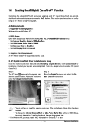
... driver if the motherboard chipset driver has been installed. • To change the Internal Graphic Mode or UMA Frame Buffer Size setting in BIOS Setup, be sure to Onboard. 3. Before you must install AMD chipset driver version 8.51 or later. - 19 - Click Xpress Install... with a discrete graphics card, ATI Hybrid CrossFireX can provide significantly advanced display performance for installation. A. BIOS Setup: Enter BIOS Setup to set the following items under the Advanced BIOS Features menu: • Set Internal Graphics Mode to UMA+SidePort. • Set UMA Frame Buffer ...
... driver if the motherboard chipset driver has been installed. • To change the Internal Graphic Mode or UMA Frame Buffer Size setting in BIOS Setup, be sure to Onboard. 3. Before you must install AMD chipset driver version 8.51 or later. - 19 - Click Xpress Install... with a discrete graphics card, ATI Hybrid CrossFireX can provide significantly advanced display performance for installation. A. BIOS Setup: Enter BIOS Setup to set the following items under the Advanced BIOS Features menu: • Set Internal Graphics Mode to UMA+SidePort. • Set UMA Frame Buffer ...
Manual
Page 21
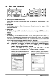
...to this port. Hardware Installation D-Sub Port The D-Sub port supports a 15-pin D-Sub connector. Refer the figures below for details.), and enter BIOS Setup, then set the Default device for sound playback is HDCP compliant. Connect a monitor that supports DVI-D connection to this port. Connect the ... Windows XP, select Start>Control Panel>Sounds and Audio Devices>Audio, set Onboard VGA output connect to D-SUB/ HDMI or Auto under Advanced BIOS Features. • Please note the HDMI audio output only supports AC3, DTS and 2-channel-LPCM formats. (AC3 and DTS require the use...
...to this port. Hardware Installation D-Sub Port The D-Sub port supports a 15-pin D-Sub connector. Refer the figures below for details.), and enter BIOS Setup, then set the Default device for sound playback is HDCP compliant. Connect a monitor that supports DVI-D connection to this port. Connect the ... Windows XP, select Start>Control Panel>Sounds and Audio Devices>Audio, set Onboard VGA output connect to D-SUB/ HDMI or Auto under Advanced BIOS Features. • Please note the HDMI audio output only supports AC3, DTS and 2-channel-LPCM formats. (AC3 and DTS require the use...
Manual
Page 22
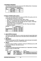
RJ-45 LAN Port The Gigabit Ethernet LAN port provides Internet connection at up to Chapter 2, "BIOS Setup," "Advanced BIOS Features," for an IEEE 1394a device. Playback of HD DVD and Blu-ray Discs: In order to get better playback quality, ...DDR2 800 memory modules with dual channel mode enabled • BIOS Setup: At least 256 MB of the LAN port LEDs. Use this port for more information) • Playback software: CyberLink PowerDVD 8.0 or later (Note: Please ensure Hardware Acceleration is occurring GA-MA790GP-UD3H Motherboard - 22 - Dual Combination Supported or Not Display DVI...
RJ-45 LAN Port The Gigabit Ethernet LAN port provides Internet connection at up to Chapter 2, "BIOS Setup," "Advanced BIOS Features," for an IEEE 1394a device. Playback of HD DVD and Blu-ray Discs: In order to get better playback quality, ...DDR2 800 memory modules with dual channel mode enabled • BIOS Setup: At least 256 MB of the LAN port LEDs. Use this port for more information) • Playback software: CyberLink PowerDVD 8.0 or later (Note: Please ensure Hardware Acceleration is occurring GA-MA790GP-UD3H Motherboard - 22 - Dual Combination Supported or Not Display DVI...
Manual
Page 28
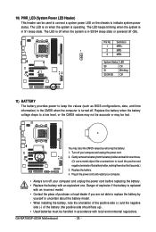
... the power cord. 2. System Status LED S0 On S1 Blinking S3/S4/S5 Off 11) BATTERY The battery provides power to indicate system power status. GA-MA790GP-UD3H Motherboard - 28 - Definition 1 MPD+ 1 2 MPD- 3 MPD- 10) PWR_LED (System Power LED Header) This header can be used to connect a system power LED on ...when the system is operating. The LED is on the chassis to keep the values (such as BIOS configurations, date, and time information) in S1 sleep state. Gently remove the battery from the battery holder and wait for 5 seconds.) 3.
... the power cord. 2. System Status LED S0 On S1 Blinking S3/S4/S5 Off 11) BATTERY The battery provides power to indicate system power status. GA-MA790GP-UD3H Motherboard - 28 - Definition 1 MPD+ 1 2 MPD- 3 MPD- 10) PWR_LED (System Power LED Header) This header can be used to connect a system power LED on ...when the system is operating. The LED is on the chassis to keep the values (such as BIOS configurations, date, and time information) in S1 sleep state. Gently remove the battery from the battery holder and wait for 5 seconds.) 3.
Manual
Page 29
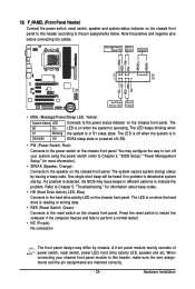
...). • SPEAK (Speaker, Orange): Connects to the speaker on the chassis front panel. The S0 On LED is on when the system is detected, the BIOS may differ by issuing a beep code. If a problem is operating. When connecting your system using the power switch (refer to Chapter... 2, "BIOS Setup," "Power Management Setup," for information about beep codes. • HD (Hard Drive Activity LED, Blue) Connects to the hard drive activity LED on the ...
...). • SPEAK (Speaker, Orange): Connects to the speaker on the chassis front panel. The S0 On LED is on when the system is detected, the BIOS may differ by issuing a beep code. If a problem is operating. When connecting your system using the power switch (refer to Chapter... 2, "BIOS Setup," "Power Management Setup," for information about beep codes. • HD (Hard Drive Activity LED, Blue) Connects to the hard drive activity LED on the ...

Manual
Page 33
.... Pin No. Definition 1 1 Signal 2 GND 20) CLR_CMOS (Clearing CMOS Jumper) Use this jumper to factory defaults. date information and BIOS configurations) and reset the CMOS values to clear the CMOS values (e.g. Hardware Installation This function requires a chassis with chassis intrusion detection design. ...To clear the CMOS values, place a jumper cap on your computer, be sure to touch the two pins for BIOS configurations). - 33 - 19) CI (Chassis Intrusion Header) This motherboard provides a chassis detection feature that detects if the chassis cover has been...
.... Pin No. Definition 1 1 Signal 2 GND 20) CLR_CMOS (Clearing CMOS Jumper) Use this jumper to factory defaults. date information and BIOS configurations) and reset the CMOS values to clear the CMOS values (e.g. Hardware Installation This function requires a chassis with chassis intrusion detection design. ...To clear the CMOS values, place a jumper cap on your computer, be sure to touch the two pins for BIOS configurations). - 33 - 19) CI (Chassis Intrusion Header) This motherboard provides a chassis detection feature that detects if the chassis cover has been...
Manual
Page 35
...keep the configuration values in the CMOS. Chapter 2 BIOS Setup BIOS (Basic Input and Output System) records hardware parameters of BIOS, it with caution. BIOS includes a BIOS Setup program that searches and downloads the latest version of the BIOS Setup program. When the power is turned on...., if you can press + in system malfunction. • BIOS will emit a beep code during system startup, saving system parameters and loading operating system, etc. To upgrade the BIOS, use either the GIGABYTE Q-Flash or @BIOS utility. • Q-Flash allows the user to activate certain ...
...keep the configuration values in the CMOS. Chapter 2 BIOS Setup BIOS (Basic Input and Output System) records hardware parameters of BIOS, it with caution. BIOS includes a BIOS Setup program that searches and downloads the latest version of the BIOS Setup program. When the power is turned on...., if you can press + in system malfunction. • BIOS will emit a beep code during system startup, saving system parameters and loading operating system, etc. To upgrade the BIOS, use either the GIGABYTE Q-Flash or @BIOS utility. • Q-Flash allows the user to activate certain ...
Manual
Page 36
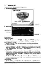
... setting as needed. : Q-FLASH Press the key to access the Q-Flash utility directly without having to set the first boot device without entering BIOS Setup. GA-MA790GP-UD3H Motherboard - 36 - GA-MA790GP-UD3H D4c . . . . : BIOS Setup/Q-Flash : XpressRecovery2 : Boot Menu : Qflash 04/27/2009-RS780D-SB750-7A66AG0DC-00 Function Keys Function Keys Function Keys: : POST SCREEN Press the...
... setting as needed. : Q-FLASH Press the key to access the Q-Flash utility directly without having to set the first boot device without entering BIOS Setup. GA-MA790GP-UD3H Motherboard - 36 - GA-MA790GP-UD3H D4c . . . . : BIOS Setup/Q-Flash : XpressRecovery2 : Boot Menu : Qflash 04/27/2009-RS780D-SB750-7A66AG0DC-00 Function Keys Function Keys Function Keys: : POST SCREEN Press the...
Manual
Page 37
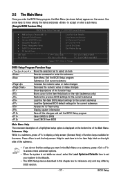
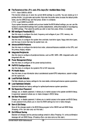
... Move cursor to the Item Help block on the bottom line of the submenu. • If you do not find the settings you enter the BIOS Setup program, the Main Menu (as usual, select the Load Optimized Defaults item to set your system to display a help screen. Use arrow keys ... Password Set User Password Save & Exit Setup Exit Without Saving ESC: Quit F8: Q-Flash Select Item F10: Save & Exit Setup F11: Save CMOS to BIOS F12: Load CMOS from BIOS Main Menu Help The onscreen description of a highlighted setup option is displayed on the right (submenus only) Restore the previous...
... Move cursor to the Item Help block on the bottom line of the submenu. • If you do not find the settings you enter the BIOS Setup program, the Main Menu (as usual, select the Load Optimized Defaults item to set your system to display a help screen. Use arrow keys ... Password Set User Password Save & Exit Setup Exit Without Saving ESC: Quit F8: Q-Flash Select Item F10: Save & Exit Setup F11: Save CMOS to BIOS F12: Load CMOS from BIOS Main Menu Help The onscreen description of a highlighted setup option is displayed on the right (submenus only) Restore the previous...
Manual
Page 38
...61550; MB Intelligent Tweaker(M.I.T.) Use this menu to configure the clock, frequency and voltages of your system becomes unstable and you have loaded the BIOS default settings, you can use the SPACE key) and then press to complete. F12 : Load CMOS from a profile created before,...menu to configure the system's PCI & PnP resources. PC Health Status Use this task.) GA-MA790GP-UD3H Motherboard - 38 - Pressing to the system and BIOS Setup. It allows you to view the BIOS settings but not to 8 profiles (Profile 1-8) and name each profile. You can also carry out ...
...61550; MB Intelligent Tweaker(M.I.T.) Use this menu to configure the clock, frequency and voltages of your system becomes unstable and you have loaded the BIOS default settings, you can use the SPACE key) and then press to complete. F12 : Load CMOS from a profile created before,...menu to configure the system's PCI & PnP resources. PC Health Status Use this task.) GA-MA790GP-UD3H Motherboard - 38 - Pressing to the system and BIOS Setup. It allows you to view the BIOS settings but not to 8 profiles (Profile 1-8) and name each profile. You can also carry out ...
Manual
Page 39
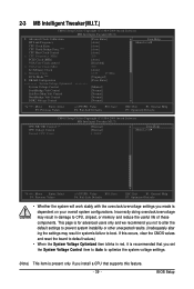
... components. This page is for advanced users only and we recommend you made is present only if you install a CPU that supports this feature. - 39 - BIOS Setup 2-3 MB Intelligent Tweaker(M.I.T.) CMOS Setup Utility-Copyright (C) 1984-2009 Award Software MB Intelligent Tweaker(M.I.T.) Advanced Clock Calibratioin HT Link Frequency [Press Enter] [Auto...
... components. This page is for advanced users only and we recommend you made is present only if you install a CPU that supports this feature. - 39 - BIOS Setup 2-3 MB Intelligent Tweaker(M.I.T.) CMOS Setup Utility-Copyright (C) 1984-2009 Award Software MB Intelligent Tweaker(M.I.T.) Advanced Clock Calibratioin HT Link Frequency [Press Enter] [Auto...


