Manual
Page 3
... this manual is 1.0. Example: For example, "REV: 1.0" means the revision of GIGABYTE. Check your motherboard looks like this manual are legally registered to the specifications and features in the use GIGABYTE's unique features, read the User's Manual. For instructions on your motherboard revision before updating motherboard BIOS, drivers, or when looking for technical information. The trademarks mentioned in this : "REV: X.X." Copyright © 2009 GIGA-BYTE TECHNOLOGY...
... this manual is 1.0. Example: For example, "REV: 1.0" means the revision of GIGABYTE. Check your motherboard looks like this manual are legally registered to the specifications and features in the use GIGABYTE's unique features, read the User's Manual. For instructions on your motherboard revision before updating motherboard BIOS, drivers, or when looking for technical information. The trademarks mentioned in this : "REV: X.X." Copyright © 2009 GIGA-BYTE TECHNOLOGY...
Manual
Page 4
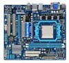
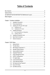
... of Contents Box Contents...6 Optional Items...6 GA-MA78LMT-S2H/GA-MA78LMT-S2 Motherboard Layout 7 Block Diagram...8 Chapter 1 Hardware Installation 9 1-1 Installation Precautions 9 1-2 Product Specifications 10 1-3 Installing the CPU and CPU Cooler 13 1-3-1 Installing the CPU 13 1-3-2 Installing the CPU Cooler 15 1-4 Installing the Memory 16 1-4-1 Dual Channel Memory Configuration 16 1-4-2 Installing a Memory 17 1-5 Installing an Expansion Card 18 1-6 Back Panel Connectors 19 1-7 Internal Connectors 21 Chapter 2 BIOS Setup 31 2-1 Startup Screen 32 2-2 The Main Menu 33 2-3 MB...
... of Contents Box Contents...6 Optional Items...6 GA-MA78LMT-S2H/GA-MA78LMT-S2 Motherboard Layout 7 Block Diagram...8 Chapter 1 Hardware Installation 9 1-1 Installation Precautions 9 1-2 Product Specifications 10 1-3 Installing the CPU and CPU Cooler 13 1-3-1 Installing the CPU 13 1-3-2 Installing the CPU Cooler 15 1-4 Installing the Memory 16 1-4-1 Dual Channel Memory Configuration 16 1-4-2 Installing a Memory 17 1-5 Installing an Expansion Card 18 1-6 Back Panel Connectors 19 1-7 Internal Connectors 21 Chapter 2 BIOS Setup 31 2-1 Startup Screen 32 2-2 The Main Menu 33 2-3 MB...
Manual
Page 10
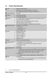
Support for SATA RAID 0, RAID 1, RAID 10, and JBOD iTE IT8718 chip: - 1 x floppy disk drive connector supporting up to 4 SATA 3Gb/s devices - 1-2 Product Specifications CPU Support for AM3 processors: AMD Phenom™ II processor/ AMD Athlon™ II processor (Go to GIGABYTE's website for the latest CPU support list.) Hyper Transport Bus 5200 MT/s Chipset Memory Onboard Graphics Audio North Bridge:...
Support for SATA RAID 0, RAID 1, RAID 10, and JBOD iTE IT8718 chip: - 1 x floppy disk drive connector supporting up to 4 SATA 3Gb/s devices - 1-2 Product Specifications CPU Support for AM3 processors: AMD Phenom™ II processor/ AMD Athlon™ II processor (Go to GIGABYTE's website for the latest CPU support list.) Hyper Transport Bus 5200 MT/s Chipset Memory Onboard Graphics Audio North Bridge:...
Manual
Page 16
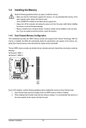
... mode. 1. After the memory is installed. 2. Enabling Dual Channel memory mode will automatically detect the specifications and capacity of the same capacity, brand, speed, and chips be enabled if only one direction. Dual Channel mode cannot be used . If you begin to install the memory: • Make sure that memory of the memory. Hardware Installation - 16 - The two DDR3 memory sockets are unable to insert the memory, switch the direction. 1-4-1 Dual Channel Memory Configuration This motherboard provides two DDR3 memory sockets and supports Dual Channel Technology...
... mode. 1. After the memory is installed. 2. Enabling Dual Channel memory mode will automatically detect the specifications and capacity of the same capacity, brand, speed, and chips be enabled if only one direction. Dual Channel mode cannot be used . If you begin to install the memory: • Make sure that memory of the memory. Hardware Installation - 16 - The two DDR3 memory sockets are unable to insert the memory, switch the direction. 1-4-1 Dual Channel Memory Configuration This motherboard provides two DDR3 memory sockets and supports Dual Channel Technology...
Manual
Page 18
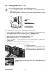
... inserted into the slot. 4. Secure the card's metal bracket to install an expansion card: • Make sure the motherboard supports the expansion card. Locate an expansion slot that came with a screw. 5. Example: Installing and Removing a PCI Express Graphics Card: • Installing a Graphics Card: Gently push down on your expansion card. • Always turn off the computer and unplug the power cord from the chassis back panel. 2. Install the driver provided with the slot, and press down...
... inserted into the slot. 4. Secure the card's metal bracket to install an expansion card: • Make sure the motherboard supports the expansion card. Locate an expansion slot that came with a screw. 5. Example: Installing and Removing a PCI Express Graphics Card: • Installing a Graphics Card: Gently push down on your expansion card. • Always turn off the computer and unplug the power cord from the chassis back panel. 2. Install the driver provided with the slot, and press down...
Manual
Page 20
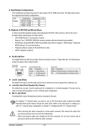
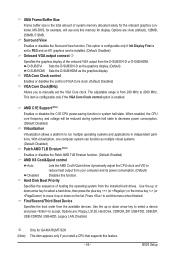
The table below . • CPU: AMD Phenom™ X3 processor or above • Memory: Two 1 GB DDR3 1066 MHz memory modules with dual channel mode enabled • BIOS Setup: At least 256 MB of UMA Frame Buffer Size (refer to Chapter 2, "BIOS Setup," "Advanced BIOS Features," for a headphone or 2-channel speaker. Connection/ Speed LED Activity LED LAN Port Connection/Speed LED: State Description Orange 1 Gbps data rate Green 100 Mbps data rate Off 10 Mbps data rate...
The table below . • CPU: AMD Phenom™ X3 processor or above • Memory: Two 1 GB DDR3 1066 MHz memory modules with dual channel mode enabled • BIOS Setup: At least 256 MB of UMA Frame Buffer Size (refer to Chapter 2, "BIOS Setup," "Advanced BIOS Features," for a headphone or 2-channel speaker. Connection/ Speed LED Activity LED LAN Port Connection/Speed LED: State Description Orange 1 Gbps data rate Green 100 Mbps data rate Off 10 Mbps data rate...
Manual
Page 28
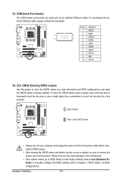
... the motherboard. • After system restart, go to BIOS Setup to load factory defaults (select Load Optimized Defaults) or manually configure the BIOS settings (refer to factory defaults. Definition 1 NDCD- 9 2 NSIN 1 3 NSOUT 10 2 4 NDTR- 5 GND 6 NDSR- 7 NRTS- 8 NCTS- 9 NRI- 10 No Pin 14) CLR_CMOS (Clearing CMOS Jumper) Use this jumper to touch the two pins for BIOS configurations). For purchasing the optional COM port cable, please contact the local dealer. Pin No. Open: Normal Short: Clear CMOS Values...
... the motherboard. • After system restart, go to BIOS Setup to load factory defaults (select Load Optimized Defaults) or manually configure the BIOS settings (refer to factory defaults. Definition 1 NDCD- 9 2 NSIN 1 3 NSOUT 10 2 4 NDTR- 5 GND 6 NDSR- 7 NRTS- 8 NCTS- 9 NRI- 10 No Pin 14) CLR_CMOS (Clearing CMOS Jumper) Use this jumper to touch the two pins for BIOS configurations). For purchasing the optional COM port cable, please contact the local dealer. Pin No. Open: Normal Short: Clear CMOS Values...
Manual
Page 34
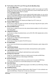
... clock, frequency and voltages of your CPU, memory, etc. Standard CMOS Features Use this menu to configure the system time and date, hard drive types, floppy disk drive types, and the type of errors that stop the system boot, etc. Advanced BIOS Features Use this menu to configure the device boot order, advanced features available on the CPU, and the primary display adapter. Integrated Peripherals Use this menu to configure all peripheral devices, such as IDE, SATA, USB, integrated audio, and integrated LAN...
... clock, frequency and voltages of your CPU, memory, etc. Standard CMOS Features Use this menu to configure the system time and date, hard drive types, floppy disk drive types, and the type of errors that stop the system boot, etc. Advanced BIOS Features Use this menu to configure the device boot order, advanced features available on the CPU, and the primary display adapter. Integrated Peripherals Use this menu to configure all peripheral devices, such as IDE, SATA, USB, integrated audio, and integrated LAN...
Manual
Page 37
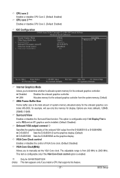
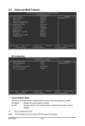
... example, will use only this memory for GA-MA78LMT-S2H (Note) This item appears only if you install a CPU that supports this feature. - 37 - This option is configurable only if Init Display First is set the VGA Core clock. VGA Core Clock control Enables or disables the control of VGA Core clock. (Default: Disabled) VGA Core Clock(MHz) Allows you to manually set to PEG and an ATI graphics card is from the D-SUB/DVI-D or D-SUB/HDMI. Surround View Enables or disables the Surround View...
... example, will use only this memory for GA-MA78LMT-S2H (Note) This item appears only if you install a CPU that supports this feature. - 37 - This option is configurable only if Init Display First is set the VGA Core clock. VGA Core Clock control Enables or disables the control of VGA Core clock. (Default: Disabled) VGA Core Clock(MHz) Allows you to manually set to PEG and an ATI graphics card is from the D-SUB/DVI-D or D-SUB/HDMI. Surround View Enables or disables the Surround View...
Manual
Page 38
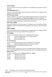
... Clock Control Enables or disables the control of CPU host clock. The adjustable range is highly recommended that supports this feature. Manual allows the CPU Frequency (MHz) item below to be configurable. (Default: Auto) Memory Clock This option is configurable only when Set Memory Clock is dependent on the CPU being used . Note: If your system fails to boot after overclocking, please wait for 20 seconds to allow for the installed CPU. Auto lets BIOS automatically set the memory clock. Set Memory Clock Determines whether to manually set...
... Clock Control Enables or disables the control of CPU host clock. The adjustable range is highly recommended that supports this feature. Manual allows the CPU Frequency (MHz) item below to be configurable. (Default: Auto) Memory Clock This option is configurable only when Set Memory Clock is dependent on the CPU being used . Note: If your system fails to boot after overclocking, please wait for 20 seconds to allow for the installed CPU. Auto lets BIOS automatically set the memory clock. Set Memory Clock Determines whether to manually set...
Manual
Page 40
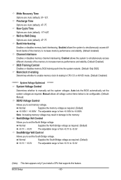
... banks of the memory to increase memory performance and stability. (Default: Enabled) DQS Training Control Enables or disables memory DQS training each time the system restarts. (Default: Skip DQS) Memclock tri-stating Determines whether to enable memory clock tri-stating in damage to +0.300V. Normal Supplies the South Bridge voltage as required. Write Recovery Time Options are : Auto (default), 4T~7T. SouthBridge Volt Control Allows you install a CPU that supports this feature.
... banks of the memory to increase memory performance and stability. (Default: Enabled) DQS Training Control Enables or disables memory DQS training each time the system restarts. (Default: Skip DQS) Memclock tri-stating Determines whether to enable memory clock tri-stating in damage to +0.300V. Normal Supplies the South Bridge voltage as required. Write Recovery Time Options are : Auto (default), 4T~7T. SouthBridge Volt Control Allows you install a CPU that supports this feature.
Manual
Page 44
... HDD Init Display First [Press Enter] [Disabled] [Disabled] [Enabled] [Auto] [Press Enter] [Floppy] [Hard Disk] [CDROM] [Setup] [Disabled] [Disabled] [Disabled] [PCI Slot] Item Help Menu Level Move Enter: Select F5: Previous Values +/-/PU/PD: Value F10: Save F6: Fail-Safe Defaults ESC: Exit F1: General Help F7: Optimized Defaults IGX Configuration CMOS Setup Utility-Copyright (C) 1984-2009 Award Software Advanced Clock Calibration Internal Graphics Mode UMA Frame Buffer Size x Surround View Onboard VGA output connectj VGA Core Clock control x VGA Core...
... HDD Init Display First [Press Enter] [Disabled] [Disabled] [Enabled] [Auto] [Press Enter] [Floppy] [Hard Disk] [CDROM] [Setup] [Disabled] [Disabled] [Disabled] [PCI Slot] Item Help Menu Level Move Enter: Select F5: Previous Values +/-/PU/PD: Value F10: Save F6: Fail-Safe Defaults ESC: Exit F1: General Help F7: Optimized Defaults IGX Configuration CMOS Setup Utility-Copyright (C) 1984-2009 Award Software Advanced Clock Calibration Internal Graphics Mode UMA Frame Buffer Size x Surround View Onboard VGA output connectj VGA Core Clock control x VGA Core...
Manual
Page 45
... system memory allocated solely for GA-MA78LMT-S2H (Note) This item appears only if you to reduce heat output from your computer and its power consumption. (Default) Disabled Disables this menu when finished. AMD C1E Support (Note) Enables or disables the C1E CPU power-saving function in independent partitions. j Only for the onboard graphics controller. Options are : Floppy, LS120, Hard Disk, CDROM, ZIP, USB-FDD, USB-ZIP, USB-CDROM, USB-HDD, Legacy LAN, Disabled. Use the up or down arrow key...
... system memory allocated solely for GA-MA78LMT-S2H (Note) This item appears only if you to reduce heat output from your computer and its power consumption. (Default) Disabled Disables this menu when finished. AMD C1E Support (Note) Enables or disables the C1E CPU power-saving function in independent partitions. j Only for the onboard graphics controller. Options are : Floppy, LS120, Hard Disk, CDROM, ZIP, USB-FDD, USB-ZIP, USB-CDROM, USB-HDD, Legacy LAN, Disabled. Use the up or down arrow key...
Manual
Page 46
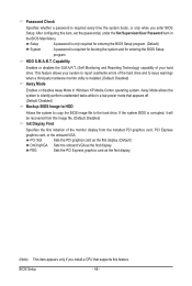
... enter BIOS Setup. BIOS Setup - 46 - HDD S.M.A.R.T. PEG Sets the PCI Express graphics card as the first display. If the system BIOS is required for booting the system and for entering the BIOS Setup program. (Default) System A password is corrupted, it will be recovered from this image file. (Default: Disabled) Init Display First Specifies the first initiation of the hard drive and to issue warnings when a third party hardware monitor utility is installed. (Default: Disabled) Away Mode Enables or disables Away Mode in a low-power mode...
... enter BIOS Setup. BIOS Setup - 46 - HDD S.M.A.R.T. PEG Sets the PCI Express graphics card as the first display. If the system BIOS is required for booting the system and for entering the BIOS Setup program. (Default) System A password is corrupted, it will be recovered from this image file. (Default: Disabled) Init Display First Specifies the first initiation of the hard drive and to issue warnings when a third party hardware monitor utility is installed. (Default: Disabled) Away Mode Enables or disables Away Mode in a low-power mode...
Manual
Page 47
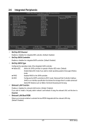
... Integrated Peripherals CMOS Setup Utility-Copyright (C) 1984-2009 Award Software Integrated Peripherals OnChip IDE Channel OnChip SATA Controller OnChip SATA Type Onboard LAN Function Onboard LAN Boot ROM } SMART LAN Onboard Audio Function Legacy USB storage detect Onboard Serial Port 1 OnChip USB Controller USB EHCI Controller USB Keyboard Support USB Mouse Support [Enabled] [Enabled] [Native IDE] [Enabled] [Disabled] [Press Enter] [Enabled] [Enabled] [3F8/IRQ4] [Enabled] [Enabled] [Enabled] [Disabled] Item Help Menu Level Move Enter: Select...
... Integrated Peripherals CMOS Setup Utility-Copyright (C) 1984-2009 Award Software Integrated Peripherals OnChip IDE Channel OnChip SATA Controller OnChip SATA Type Onboard LAN Function Onboard LAN Boot ROM } SMART LAN Onboard Audio Function Legacy USB storage detect Onboard Serial Port 1 OnChip USB Controller USB EHCI Controller USB Keyboard Support USB Mouse Support [Enabled] [Enabled] [Native IDE] [Enabled] [Disabled] [Press Enter] [Enabled] [Enabled] [3F8/IRQ4] [Enabled] [Enabled] [Enabled] [Disabled] Item Help Menu Level Move Enter: Select...
Manual
Page 50
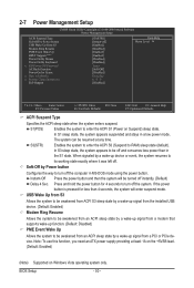
... from a PCI or PCIe device. If the power button is pressed for 4 seconds to turn off the computer in MS-DOS mode using the power button. 2-7 Power Management Setup CMOS Setup Utility-Copyright (C) 1984-2009 Award Software Power Management Setup ACPI Suspend Type Soft-Off by Power button USB Wake Up from S3 Modem Ring Resume PME Event Wake Up HPET Support (Note) Power On By Mouse Power On By Keyboard x KB Power ON Password AC Back Function Power-On by a wake-up device or...
... from a PCI or PCIe device. If the power button is pressed for 4 seconds to turn off the computer in MS-DOS mode using the power button. 2-7 Power Management Setup CMOS Setup Utility-Copyright (C) 1984-2009 Award Software Power Management Setup ACPI Suspend Type Soft-Off by Power button USB Wake Up from S3 Modem Ring Resume PME Event Wake Up HPET Support (Note) Power On By Mouse Power On By Keyboard x KB Power ON Password AC Back Function Power-On by a wake-up device or...
Manual
Page 73
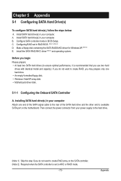
... SATA hard drive and the other end to AHCI or RAID mode. - 73 - C. Configuring RAID set to available SATA port on the SATA controller. (Note 2) Required when the SATA controller is set in BIOS Setup. Then connect the power connector from your computer. Install SATA hard drive(s) in your computer Attach one hard drive. • An empty formatted floppy disk. • Windows Vista/XP setup disk. • Motherboard driver disk. 5-1-1 Configuring the Onboard SATA Controller A. Appendix Chapter 5 Appendix 5-1 Configuring SATA Hard Drive(s) To configure SATA hard drive...
... SATA hard drive and the other end to AHCI or RAID mode. - 73 - C. Configuring RAID set to available SATA port on the SATA controller. (Note 2) Required when the SATA controller is set in BIOS Setup. Then connect the power connector from your computer. Install SATA hard drive(s) in your computer Attach one hard drive. • An empty formatted floppy disk. • Windows Vista/XP setup disk. • Motherboard driver disk. 5-1-1 Configuring the Onboard SATA Controller A. Appendix Chapter 5 Appendix 5-1 Configuring SATA Hard Drive(s) To configure SATA hard drive...
Manual
Page 79
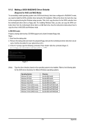
...Boot from the motherboard driver disk to install the SATA controller driver during the Windows setup process. 5-1-2 Making a SATA RAID/AHCI Driver Diskette (Required for AHCI and RAID Mode) To successfully install operating system onto SATA hard drive(s) that is D:\). 3: At the A:\> prompt, type the following table for the SATA driver directories for the SATA controller from the motherboard driver disk to RAID/AHCI mode, you also can copy the SATA controller driver from the startup disk. 2: Remove the startup disk and insert the prepared floppy disk and the motherboard driver...
...Boot from the motherboard driver disk to install the SATA controller driver during the Windows setup process. 5-1-2 Making a SATA RAID/AHCI Driver Diskette (Required for AHCI and RAID Mode) To successfully install operating system onto SATA hard drive(s) that is D:\). 3: At the A:\> prompt, type the following table for the SATA driver directories for the SATA controller from the motherboard driver disk to RAID/AHCI mode, you also can copy the SATA controller driver from the startup disk. 2: Remove the startup disk and insert the prepared floppy disk and the motherboard driver...
Manual
Page 81
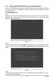
... with Windows, using a device support disk provided by an adapter manufacturer. Appendix A. AMD AHCI Compatible RAID Controller-x86 platform AMD AHCI Compatible RAID Controller-x64 platform ENTER=Select F3=Exit Step 3: Figure 2 On the next screen, press to install Windows Vista/ XP onto your system to boot from the following list, or press ESC to return to install a 3rd party SCSI or RAID driver" (Figure 1). 5-1-3 Installing the SATA RAID/AHCI Driver and Operating System With the SATA RAID/AHCI driver diskette and correct BIOS settings...
... with Windows, using a device support disk provided by an adapter manufacturer. Appendix A. AMD AHCI Compatible RAID Controller-x86 platform AMD AHCI Compatible RAID Controller-x64 platform ENTER=Select F3=Exit Step 3: Figure 2 On the next screen, press to install Windows Vista/ XP onto your system to boot from the following list, or press ESC to return to install a 3rd party SCSI or RAID driver" (Figure 1). 5-1-3 Installing the SATA RAID/AHCI Driver and Operating System With the SATA RAID/AHCI driver diskette and correct BIOS settings...
Manual
Page 93
... battery from GIGABYTE's website to install. A: The following Award BIOS beep code descriptions may help you identify possible computer problems. (For reference only.) 1 short: System boots successfully 1 long, 3 short: Keyboard error 2 short: CMOS setting error 1 long, 9 short: BIOS ROM error 1 long, 1 short: Memory or motherboard error Continuous long beeps: Graphics card not inserted properly 1 long, 2 short: Monitor or graphics card error Continuous short beeps: Power error - 93 - Appendix Press to show the advanced options. Q: How do I install the onboard HD audio driver...
... battery from GIGABYTE's website to install. A: The following Award BIOS beep code descriptions may help you identify possible computer problems. (For reference only.) 1 short: System boots successfully 1 long, 3 short: Keyboard error 2 short: CMOS setting error 1 long, 9 short: BIOS ROM error 1 long, 1 short: Memory or motherboard error Continuous long beeps: Graphics card not inserted properly 1 long, 2 short: Monitor or graphics card error Continuous short beeps: Power error - 93 - Appendix Press to show the advanced options. Q: How do I install the onboard HD audio driver...


