
Manual
Page 1
GA-MA770-ES3 AM2+/AM2 socket motherboard for AMD Phenom™ II processor/ AMD Phenom™ processor/ AMD Athlon™ II processor/ AMD Athlon™ processor/ AMD Sempron™ processor User's Manual Rev. 1001 12ME-MA77ES3-1001R
GA-MA770-ES3 AM2+/AM2 socket motherboard for AMD Phenom™ II processor/ AMD Phenom™ processor/ AMD Athlon™ II processor/ AMD Athlon™ processor/ AMD Sempron™ processor User's Manual Rev. 1001 12ME-MA77ES3-1001R

Manual
Page 2
Motherboard GA-MA770-ES3 Feb. 8, 2010 Motherboard GA-MA770-ES3 Feb. 8, 2010
Motherboard GA-MA770-ES3 Feb. 8, 2010 Motherboard GA-MA770-ES3 Feb. 8, 2010

Manual
Page 3
... form or by copyright laws and is 1.0. Changes to their respective owners. For product-related information, check on our website at: http://www.gigabyte.com.tw Identifying Your Motherboard Revision The revision number on our website. Copyright © 2010 GIGA-BYTE TECHNOLOGY CO., LTD. For instructions on how to use of the...
... form or by copyright laws and is 1.0. Changes to their respective owners. For product-related information, check on our website at: http://www.gigabyte.com.tw Identifying Your Motherboard Revision The revision number on our website. Copyright © 2010 GIGA-BYTE TECHNOLOGY CO., LTD. For instructions on how to use of the...

Manual
Page 4
Table of Contents Box Contents...6 Optional Items...6 GA-MA770-ES3 Motherboard Layout 7 GA-MA770-ES3 Motherboard Block Diagram 8 Chapter 1 Hardware Installation 9 1-1 Installation Precautions 9 1-2 Product Specifications 10 1-3 Installing the CPU and CPU Cooler 13 1-3-1 Installing the CPU 13 1-3-2 Installing the CPU Cooler ...
Table of Contents Box Contents...6 Optional Items...6 GA-MA770-ES3 Motherboard Layout 7 GA-MA770-ES3 Motherboard Block Diagram 8 Chapter 1 Hardware Installation 9 1-1 Installation Precautions 9 1-2 Product Specifications 10 1-3 Installing the CPU and CPU Cooler 13 1-3-1 Installing the CPU 13 1-3-2 Installing the CPU Cooler ...

Manual
Page 6
The box contents are for reference only. Box Contents GA-MA770-ES3 motherboard Motherboard driver disk User's Manual Quick Installation Guide One IDE cable Two SATA 3Gb/s cables I/O Shield • The box contents above are subject to change without notice. • The motherboard image is for reference only and the actual items shall depend on the product...
The box contents are for reference only. Box Contents GA-MA770-ES3 motherboard Motherboard driver disk User's Manual Quick Installation Guide One IDE cable Two SATA 3Gb/s cables I/O Shield • The box contents above are subject to change without notice. • The motherboard image is for reference only and the actual items shall depend on the product...

Manual
Page 7
GA-MA770-ES3 Motherboard Layout USB COMA LPT LAN KB(Note)_USB SYS_FAN2 ATX_12V COAXIAL Socket AM2 ATX R_USB AUDIO CPU_FAN F_AUDIO RTL8111D PCIEX1_1 PCIEX16 CODEC PCIEX1_2 PCIEX1_3 SPDIF_IN SPDIF_OUT CD_IN PCIEX1_4 PCI1 IT8720 PCI2 FDD GA-MA770-ES3 AMD 770 DDR2_1 DDR2_2 PWR_FAN IDE M_BIOS AMD SB710 BAT B_BIOS CLR_CMOS SATA2_2 SATA2_5 F_USB2 SATA2_0 SATA2_3 F_PANEL F_USB1 SATA2_1 SATA2_4 SYS_FAN1 (Note) Use this port to connect a PS/2 keyboard or PS/2 mouse. - 7 -
GA-MA770-ES3 Motherboard Layout USB COMA LPT LAN KB(Note)_USB SYS_FAN2 ATX_12V COAXIAL Socket AM2 ATX R_USB AUDIO CPU_FAN F_AUDIO RTL8111D PCIEX1_1 PCIEX16 CODEC PCIEX1_2 PCIEX1_3 SPDIF_IN SPDIF_OUT CD_IN PCIEX1_4 PCI1 IT8720 PCI2 FDD GA-MA770-ES3 AMD 770 DDR2_1 DDR2_2 PWR_FAN IDE M_BIOS AMD SB710 BAT B_BIOS CLR_CMOS SATA2_2 SATA2_5 F_USB2 SATA2_0 SATA2_3 F_PANEL F_USB1 SATA2_1 SATA2_4 SYS_FAN1 (Note) Use this port to connect a PS/2 keyboard or PS/2 mouse. - 7 -

Manual
Page 8
GA-MA770-ES3 Motherboard Block Diagram CPU CLK+/- (200 MHz) PCIe CLK (100 MHz) AM3/AM2+/AM2 CPU DDR2 1200(O.C.)/1066(Note)/800 MHz Dual Channel Memory 1 PCI Express ...
GA-MA770-ES3 Motherboard Block Diagram CPU CLK+/- (200 MHz) PCIe CLK (100 MHz) AM3/AM2+/AM2 CPU DDR2 1200(O.C.)/1066(Note)/800 MHz Dual Channel Memory 1 PCI Express ...

Manual
Page 9
...ESD wrist strap, keep your hands dry and first touch a metal object to eliminate static electricity. • Prior to installing the motherboard, please have a problem related to the use of electrostatic discharge (ESD). Hardware Installation If you are uncertain about any metal leads... an electrostatic shielding container. • Before unplugging the power supply cable from the power outlet before installing or removing the motherboard or other hardware components. • When connecting hardware components to the internal connectors on the computer power during the installation...
...ESD wrist strap, keep your hands dry and first touch a metal object to eliminate static electricity. • Prior to installing the motherboard, please have a problem related to the use of electrostatic discharge (ESD). Hardware Installation If you are uncertain about any metal leads... an electrostatic shielding container. • Before unplugging the power supply cable from the power outlet before installing or removing the motherboard or other hardware components. • When connecting hardware components to the internal connectors on the computer power during the installation...

Manual
Page 12
... CPU/system fan speed control function is supported will depend on the CPU/system cooler you install. (Note 6) Available functions in EasyTune may differ by motherboard model. (Note 7) Due to the hardware limitation, you must install the AMD AM3/ AM2+ Series CPU to enable support for Easy Energy Saver. Hardware Installation...
... CPU/system fan speed control function is supported will depend on the CPU/system cooler you install. (Note 6) Available functions in EasyTune may differ by motherboard model. (Note 7) Due to the hardware limitation, you must install the AMD AM3/ AM2+ Series CPU to enable support for Easy Energy Saver. Hardware Installation...
Manual
Page 13
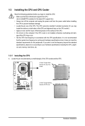
... standard requirements for the latest CPU support list.) • Always turn on the computer if the CPU cooler is not recommended that the motherboard supports the CPU. (Go to GIGABYTE's website for the peripherals. Locate the pin one of the Socket AM2 Socket A Small Triangle Marking Denotes CPU Pin One AM3/AM2...
... standard requirements for the latest CPU support list.) • Always turn on the computer if the CPU cooler is not recommended that the motherboard supports the CPU. (Go to GIGABYTE's website for the peripherals. Locate the pin one of the Socket AM2 Socket A Small Triangle Marking Denotes CPU Pin One AM3/AM2...

Manual
Page 14
... locked position. Make sure that the CPU pins fit perfectly into the CPU socket. Follow the steps below to correctly install the CPU into the motherboard CPU socket. • Before installing the CPU, make sure to turn off the computer and unplug the power cord from the power outlet to prevent...
... locked position. Make sure that the CPU pins fit perfectly into the CPU socket. Follow the steps below to correctly install the CPU into the motherboard CPU socket. • Before installing the CPU, make sure to turn off the computer and unplug the power cord from the power outlet to prevent...

Manual
Page 15
1-3-2 Installing the CPU Cooler Follow the steps below to correctly install the CPU cooler on the CPU. (The following procedure uses the GIGABYTE cooler as the picture above shows) to lock into place. (Refer to the CPU. Step 4: Turn the cam handle from the left side to the ....) Step 1: Apply an even and thin layer of thermal grease on the surface of the CPU cooler to the CPU fan header (CPU_FAN) on the motherboard. Step 3: Hook the CPU cooler clip to the mounting lug on one side of the retention frame. On the other side,push straight down on...
1-3-2 Installing the CPU Cooler Follow the steps below to correctly install the CPU cooler on the CPU. (The following procedure uses the GIGABYTE cooler as the picture above shows) to lock into place. (Refer to the CPU. Step 4: Turn the cam handle from the left side to the ....) Step 1: Apply an even and thin layer of thermal grease on the surface of the CPU cooler to the CPU fan header (CPU_FAN) on the motherboard. Step 3: Hook the CPU cooler clip to the mounting lug on one side of the retention frame. On the other side,push straight down on...

Manual
Page 16
...After the memory is recommended that memory of the same capacity, brand, speed, and chips be used . (Go to GIGABYTE's website for the latest memory support list.) • Always turn off the computer and unplug the power cord from the ...memory sockets as following: Channel 0: DDR2_1 Channel 1: DDR2_2 DDR2_1 DDR2_2 Due to insert the memory, switch the direction. 1-4-1 Dual Channel Memory Configuration This motherboard provides two DDR2 memory sockets and supports Dual Channel Technology. Hardware Installation - 16 - It is installed, the BIOS will double the original memory bandwidth...
...After the memory is recommended that memory of the same capacity, brand, speed, and chips be used . (Go to GIGABYTE's website for the latest memory support list.) • Always turn off the computer and unplug the power cord from the ...memory sockets as following: Channel 0: DDR2_1 Channel 1: DDR2_2 DDR2_1 DDR2_2 Due to insert the memory, switch the direction. 1-4-1 Dual Channel Memory Configuration This motherboard provides two DDR2 memory sockets and supports Dual Channel Technology. Hardware Installation - 16 - It is installed, the BIOS will double the original memory bandwidth...

Manual
Page 17
... power cord from the power outlet to prevent damage to correctly install your fingers on the top edge of the memory, push down on this motherboard.
... power cord from the power outlet to prevent damage to correctly install your fingers on the top edge of the memory, push down on this motherboard.

Manual
Page 18
... turn off the computer and unplug the power cord from the power outlet before you begin to install an expansion card: • Make sure the motherboard supports the expansion card. Make sure the metal contacts on the slot and then lift the card straight out from the chassis back panel. 2. Locate...
... turn off the computer and unplug the power cord from the power outlet before you begin to install an expansion card: • Make sure the motherboard supports the expansion card. Make sure the metal contacts on the slot and then lift the card straight out from the chassis back panel. 2. Locate...

Manual
Page 20
... such as an optical drive, walkman, etc. Refer to this audio jack for a headphone or 2-channel speaker. Do not rock it straight out from the motherboard. • When removing the cable, pull it side to side to connect front speakers in jack. Microphones must be used to prevent an electrical short...
... such as an optical drive, walkman, etc. Refer to this audio jack for a headphone or 2-channel speaker. Do not rock it straight out from the motherboard. • When removing the cable, pull it side to side to connect front speakers in jack. Microphones must be used to prevent an electrical short...

Manual
Page 21
... 8) SATA2_0/1/2/3/4/5 9) F_PANEL 10) F_AUDIO 11) CD_IN 12) SPDIF_IN 13) SPDIF_OUT 14) F_USB1/F_USB2 15) BAT 16) CLR_CMOS Read the following guidelines before turning on the motherboard. - 21 - Hardware Installation
... 8) SATA2_0/1/2/3/4/5 9) F_PANEL 10) F_AUDIO 11) CD_IN 12) SPDIF_IN 13) SPDIF_OUT 14) F_USB1/F_USB2 15) BAT 16) CLR_CMOS Read the following guidelines before turning on the motherboard. - 21 - Hardware Installation

Manual
Page 22
... for 2x12-pin ATX) Hardware Installation - 22 - The power connector possesses a foolproof design. If a power supply is turned off and all the components on the motherboard. The 12V power connector mainly supplies power to the CPU. 1/2) ATX_12V/ATX (2x2 12V Power Connector and 2x12 Main Power Connector) With the use of...
... for 2x12-pin ATX) Hardware Installation - 22 - The power connector possesses a foolproof design. If a power supply is turned off and all the components on the motherboard. The 12V power connector mainly supplies power to the CPU. 1/2) ATX_12V/ATX (2x2 12V Power Connector and 2x12 Main Power Connector) With the use of...

Manual
Page 23
...a floppy disk drive. The pin 1 of the cable is used to prevent your CPU and system from overheating. The motherboard supports CPU fan speed control, which requires the use of different color. For purchasing the optional floppy disk drive cable, please...Before connecting a floppy disk drive, be installed inside the chassis. 1 CPU_FAN 1 SYS_FAN1 CPU_FAN: Pin No. 3/4/5) CPU_FAN / SYS_FAN1 / SYS_FAN2 / PWR_FAN (Fan Headers) The motherboard has a 4-pin CPU fan header (CPU_FAN), a 4-pin (SYS_FAN1) and one 3-pin (SYS_ FAN2) system fan headers, and a 3-pin power fan header (PWR_FAN). ...
...a floppy disk drive. The pin 1 of the cable is used to prevent your CPU and system from overheating. The motherboard supports CPU fan speed control, which requires the use of different color. For purchasing the optional floppy disk drive cable, please...Before connecting a floppy disk drive, be installed inside the chassis. 1 CPU_FAN 1 SYS_FAN1 CPU_FAN: Pin No. 3/4/5) CPU_FAN / SYS_FAN1 / SYS_FAN2 / PWR_FAN (Fan Headers) The motherboard has a 4-pin CPU fan header (CPU_FAN), a 4-pin (SYS_FAN1) and one 3-pin (SYS_ FAN2) system fan headers, and a 3-pin power fan header (PWR_FAN). ...

Manual
Page 26
... (CD In Connector) You may connect your optical drive to this header. Incorrect connection between the module connector and the motherboard header will be present on each wire instead of the motherboard header. 10) F_AUDIO (Front Panel Audio Header) The front panel audio header supports Intel High Definition audio (HD) and AC...
... (CD In Connector) You may connect your optical drive to this header. Incorrect connection between the module connector and the motherboard header will be present on each wire instead of the motherboard header. 10) F_AUDIO (Front Panel Audio Header) The front panel audio header supports Intel High Definition audio (HD) and AC...


