Manual
Page 4
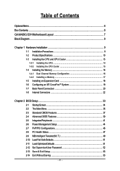
... ...6 GA-MA69G-S3H Motherboard Layout 7 Block Diagram ...8 Chapter 1 Hardware Installation 9 1-1 Installation Precautions 9 1-2 Product Specifications 10 1-3 Installing the CPU and CPU Cooler 13 1-3-1 Installing the CPU 13 1-3-2 Installing the CPU Cooler 15 1-4 Installing the Memory 16 1-4-1 Dual Channel Memory Configuration 16 1-4-2 Installing a Memory 17 1-5 Installing an Expansion Card 18 1-6 Configuring an ATI CrossFireTM System 19 1-7 Back Panel Connectors 20 1-8 Internal Connectors 22 Chapter 2 BIOS Setup 33 2-1 Startup Screen 34 2-2 The Main Menu 35 2-3 Standard CMOS...
... ...6 GA-MA69G-S3H Motherboard Layout 7 Block Diagram ...8 Chapter 1 Hardware Installation 9 1-1 Installation Precautions 9 1-2 Product Specifications 10 1-3 Installing the CPU and CPU Cooler 13 1-3-1 Installing the CPU 13 1-3-2 Installing the CPU Cooler 15 1-4 Installing the Memory 16 1-4-1 Dual Channel Memory Configuration 16 1-4-2 Installing a Memory 17 1-5 Installing an Expansion Card 18 1-6 Configuring an ATI CrossFireTM System 19 1-7 Back Panel Connectors 20 1-8 Internal Connectors 22 Chapter 2 BIOS Setup 33 2-1 Startup Screen 34 2-2 The Main Menu 35 2-3 Standard CMOS...
Manual
Page 10
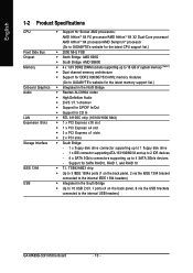
... Š High Definition Audio Š 2/4/5.1/7.1-channel Š Support for S/PDIF In/Out Š Support for SATA RAID 0, RAID 1, and RAID 10 Š T.I. Support for CD In Š RTL 8110SC chip (10/100/1000 Mbit) Š 1 x PCI Express x16 slot Š 1 x PCI Express x4 slot Š 3 x PCI Express x1 slots Š 2 x PCI slots Š South Bridge: - 1 x floppy disk drive connector supporting up to 1 floppy disk drive - 1 x IDE connector supporting ATA-133/100/66/33 and up to 2 IDE devices - 4 x SATA 3Gb/s connectors supporting up to the internal USB headers) GA-MA69G-S3H Motherboard - 10...
... Š High Definition Audio Š 2/4/5.1/7.1-channel Š Support for S/PDIF In/Out Š Support for SATA RAID 0, RAID 1, and RAID 10 Š T.I. Support for CD In Š RTL 8110SC chip (10/100/1000 Mbit) Š 1 x PCI Express x16 slot Š 1 x PCI Express x4 slot Š 3 x PCI Express x1 slots Š 2 x PCI slots Š South Bridge: - 1 x floppy disk drive connector supporting up to 1 floppy disk drive - 1 x IDE connector supporting ATA-133/100/66/33 and up to 2 IDE devices - 4 x SATA 3Gb/s connectors supporting up to the internal USB headers) GA-MA69G-S3H Motherboard - 10...
Manual
Page 16
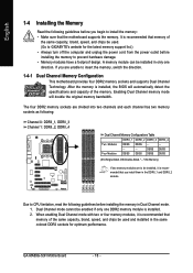
... GIGABYTE's website for the latest memory support list.) • Always turn off the computer and unplug the power cord from the power outlet before installing the memory in the same colored DDR2 sockets for optimum performance. Enabling Dual Channel memory mode will automatically detect the specifications and capacity of the same capacity, brand, speed, and chips be enabled if only one direction. After the memory is recommended that memory of the memory. GA-MA69G-S3H Motherboard...
... GIGABYTE's website for the latest memory support list.) • Always turn off the computer and unplug the power cord from the power outlet before installing the memory in the same colored DDR2 sockets for optimum performance. Enabling Dual Channel memory mode will automatically detect the specifications and capacity of the same capacity, brand, speed, and chips be enabled if only one direction. After the memory is recommended that memory of the memory. GA-MA69G-S3H Motherboard...
Manual
Page 18
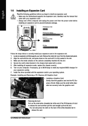
... BIOS changes for your computer. If necessary, go to BIOS Setup to install an expansion card: • Make sure the motherboard supports the expansion card. Turn on the card until it is fully seated in the expansion slot. 1. drawable bar at the end of the white-drawable bar to the chassis back panel with your operating system. Secure the card's metal bracket to release the card. GA-MA69G-S3H Motherboard...
... BIOS changes for your computer. If necessary, go to BIOS Setup to install an expansion card: • Make sure the motherboard supports the expansion card. Turn on the card until it is fully seated in the expansion slot. 1. drawable bar at the end of the white-drawable bar to the chassis back panel with your operating system. Secure the card's metal bracket to release the card. GA-MA69G-S3H Motherboard...
Manual
Page 19
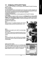
.... (Start your system with your graphics cards for CrossFire, make sure to set Init Display First to fully support an CrossFire configuration and other components in your overall system configurations. BIOS Settings: Before configuring your system for more information about enabling CrossFire.) Step 3: Connect your LCD monitor cable to the manual that is currrently supported by graphics cards. C. Graphics Card Driver Setting: After installing the graphics card driver in your D-Sub monitor via a DVIto-D-Sub adapter). We recommend a power supply...
.... (Start your system with your graphics cards for CrossFire, make sure to set Init Display First to fully support an CrossFire configuration and other components in your overall system configurations. BIOS Settings: Before configuring your system for more information about enabling CrossFire.) Step 3: Connect your LCD monitor cable to the manual that is currrently supported by graphics cards. C. Graphics Card Driver Setting: After installing the graphics card driver in your D-Sub monitor via a DVIto-D-Sub adapter). We recommend a power supply...
Manual
Page 21
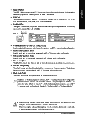
... LAN link is not established Center/Subwoofer Speaker Out Jack (Orange) Use this port for line in devices such as an USB keyboard/mouse, USB printer, USB flash drive and etc. In addition to the default speakers settings, the ~ audio jacks can be reconfigured to connect front speakers in a 5.1/7.1-channel audio configuration. Do not rock it straight out from the connector. This jack can be used to perform different functions via the audio software. Use...
... LAN link is not established Center/Subwoofer Speaker Out Jack (Orange) Use this port for line in devices such as an USB keyboard/mouse, USB printer, USB flash drive and etc. In addition to the default speakers settings, the ~ audio jacks can be reconfigured to connect front speakers in a 5.1/7.1-channel audio configuration. Do not rock it straight out from the connector. This jack can be used to perform different functions via the audio software. Use...
Manual
Page 24
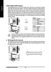
... heat dissipation, it in damage to prevent your CPU and system from overheating. Each fan header supplies a +12V power voltage and possesses a foolproof insertion design. The types of a CPU fan with color-coded power connector wires. English 3/4) CPU_FAN/SYS_FAN (Fan Headers) The motherboard has a 4-pin CPU fan header (CPU_FAN) and a 3-pin system fan header (SYS_FAN). When connecting a fan cable, be installed inside the chassis. Do not place a jumper cap on the connector. 33 1 34 2 GA-MA69G-S3H Motherboard - 24 - Most fans are not configuration jumper blocks.
... heat dissipation, it in damage to prevent your CPU and system from overheating. Each fan header supplies a +12V power voltage and possesses a foolproof insertion design. The types of a CPU fan with color-coded power connector wires. English 3/4) CPU_FAN/SYS_FAN (Fan Headers) The motherboard has a 4-pin CPU fan header (CPU_FAN) and a 3-pin system fan header (SYS_FAN). When connecting a fan cable, be installed inside the chassis. Do not place a jumper cap on the connector. 33 1 34 2 GA-MA69G-S3H Motherboard - 24 - Most fans are not configuration jumper blocks.
Manual
Page 31
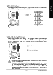
... pins to temporarily short the two pins or use a metal object like a screwdriver to clear the CMOS values (e.g. Failure to do so may cause damage to the motherboard. • After system restart, go to BIOS Setup to load factory defaults (select Load Optimized Defaults) or manually configure the BIOS settings (refer to Chapter 2, "BIOS Setup," for a few seconds. English 17) COM (Serial Port Header) The COM header can provide one serial port via an optional COM port cable. Hardware Installation...
... pins to temporarily short the two pins or use a metal object like a screwdriver to clear the CMOS values (e.g. Failure to do so may cause damage to the motherboard. • After system restart, go to BIOS Setup to load factory defaults (select Load Optimized Defaults) or manually configure the BIOS settings (refer to Chapter 2, "BIOS Setup," for a few seconds. English 17) COM (Serial Port Header) The COM header can provide one serial port via an optional COM port cable. Hardware Installation...

Manual
Page 36
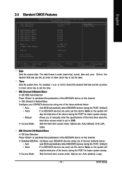
....) GA-MA69G-S3H Motherboard - 36 - An user password only allows you to make changes. „ Save & Exit Setup Save all the power-saving functions. „ PnP/PCI Configurations Use this menu to configure the system's PCI & PnP resources. „ PC Health Status Use this menu to see information about autodetected system/CPU temperature, system voltage and fan speed, etc. „ MB Intelligent Tweaker(M.I.T.) Use this menu to configure the clock, frequency and voltages of your CPU, memory, etc. „ Load Fail-Safe Defaults...
....) GA-MA69G-S3H Motherboard - 36 - An user password only allows you to make changes. „ Save & Exit Setup Save all the power-saving functions. „ PnP/PCI Configurations Use this menu to configure the system's PCI & PnP resources. „ PC Health Status Use this menu to see information about autodetected system/CPU temperature, system voltage and fan speed, etc. „ MB Intelligent Tweaker(M.I.T.) Use this menu to configure the clock, frequency and voltages of your CPU, memory, etc. „ Load Fail-Safe Defaults...
Manual
Page 37
... IDE/SATA devices are used , set this item to CHS. For example, 1 p.m. IDE Channel 0 Master/Slave IDE HDD Auto-Detection Press to autodetect the parameters of the IDE/SATA device on this channel. IDE Channel 2/3 Master/Slave IDE Auto-Detection Press to autodetect the parameters of the IDE/SATA device on this channel. Options are : Auto (default), CHS, LBA, Large. BIOS Setup Access Mode Sets the hard drive access mode. English 2-3 Standard CMOS Features Date (mm:dd:yy) Time (hh:mm:ss) CMOS Setup Utility-Copyright (C) 1984-2007 Award Software...
... IDE/SATA devices are used , set this item to CHS. For example, 1 p.m. IDE Channel 0 Master/Slave IDE HDD Auto-Detection Press to autodetect the parameters of the IDE/SATA device on this channel. IDE Channel 2/3 Master/Slave IDE Auto-Detection Press to autodetect the parameters of the IDE/SATA device on this channel. Options are : Auto (default), CHS, LBA, Large. BIOS Setup Access Mode Sets the hard drive access mode. English 2-3 Standard CMOS Features Date (mm:dd:yy) Time (hh:mm:ss) CMOS Setup Utility-Copyright (C) 1984-2007 Award Software...
Manual
Page 39
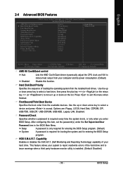
.... (Default) Disable this item, set the password(s) under the Set Supervisor/User Password item in the BIOS Main Menu. Options are: Floppy, LS120, Hard Disk, CDROM, ZIP, USB-FDD, USB-ZIP, USB-CDROM, USB-HDD, Legacy LAN, Disabled. Password Check Specifies whether a password is required for booting the system and for entering the BIOS Setup program. Capability Away Mode Full Screen LOGO Show Init Display First x Surroundview Internal Graphics Mode Frame Buffer Size Current UMA Size [Auto] [Press Enter] [Floppy] [Hard Disk] [CDROM] [Setup] [Disabled] [Disabled] [Enabled] [PCI Slot...
.... (Default) Disable this item, set the password(s) under the Set Supervisor/User Password item in the BIOS Main Menu. Options are: Floppy, LS120, Hard Disk, CDROM, ZIP, USB-FDD, USB-ZIP, USB-CDROM, USB-HDD, Legacy LAN, Disabled. Password Check Specifies whether a password is required for booting the system and for entering the BIOS Setup program. Capability Away Mode Full Screen LOGO Show Init Display First x Surroundview Internal Graphics Mode Frame Buffer Size Current UMA Size [Auto] [Press Enter] [Floppy] [Hard Disk] [CDROM] [Setup] [Disabled] [Disabled] [Enabled] [PCI Slot...
Manual
Page 40
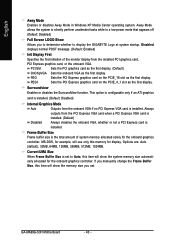
... onboard graphics controller. PCI Slot Sets the PCI graphics card as the first display. (Default) OnChipVGA Sets the onboard VGA as the first display. This option is configurable only if an ATI graphics card is installed. (Default: Disabled) Internal Graphics Mode Auto Outputs from the PCI Express VGA card when a PCI Express VGA card is installed. (Default) Disabled Always disables the onboard VGA, whether or not a PCI Express card is set . MS-DOS, for display. Surroundview Enables or disables the SurroundView function. GA-MA69G-S3H Motherboard - 40 - PEG Sets...
... onboard graphics controller. PCI Slot Sets the PCI graphics card as the first display. (Default) OnChipVGA Sets the onboard VGA as the first display. This option is configurable only if an ATI graphics card is installed. (Default: Disabled) Internal Graphics Mode Auto Outputs from the PCI Express VGA card when a PCI Express VGA card is installed. (Default) Disabled Always disables the onboard VGA, whether or not a PCI Express card is set . MS-DOS, for display. Surroundview Enables or disables the SurroundView function. GA-MA69G-S3H Motherboard - 40 - PEG Sets...
Manual
Page 42
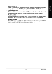
.... Windows 9X/ME SATA ->AHCI Configures the SATA controller to operate in MS-DOS. (Default: Disabled) Legacy USB storage detect Determines whether to detect USB storage devices, including USB flash drives and USB hard drives during the POST. (Default: Enabled) GA-MA69G-S3H Motherboard - 42 - For more information about AHCI, please visit Intel's website. Set this item to install a 3rd party add-in network card instead of using the onboard audio, set this option to Legacy IDE if you wish to install operating systems that allows the storage driver to activate the boot ROM...
.... Windows 9X/ME SATA ->AHCI Configures the SATA controller to operate in MS-DOS. (Default: Disabled) Legacy USB storage detect Determines whether to detect USB storage devices, including USB flash drives and USB hard drives during the POST. (Default: Enabled) GA-MA69G-S3H Motherboard - 42 - For more information about AHCI, please visit Intel's website. Set this item to install a 3rd party add-in network card instead of using the onboard audio, set this option to Legacy IDE if you wish to install operating systems that allows the storage driver to activate the boot ROM...
Manual
Page 43
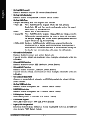
.../IRQ7, Disabled. Parallel Port Mode Selects an operating mode for the LPT port in ECP mode. This item is configurable only if Parallel Port Mode is set to ECP or ECP+EPP mode. Onboard Parallel Port Enables or disables the onboard parallel port (LPT) and specifies its base I /O address and corresponding interrupt. ECP Mode Use DMA Selects DMA channel for the onboard parallel (LPT) port. Options are : 3 (default), 1. - 43 - English Onboard Serial Port Enables or disables the first serial port and...
.../IRQ7, Disabled. Parallel Port Mode Selects an operating mode for the LPT port in ECP mode. This item is configurable only if Parallel Port Mode is set to ECP or ECP+EPP mode. Onboard Parallel Port Enables or disables the onboard parallel port (LPT) and specifies its base I /O address and corresponding interrupt. ECP Mode Use DMA Selects DMA channel for the onboard parallel (LPT) port. Options are : 3 (default), 1. - 43 - English Onboard Serial Port Enables or disables the first serial port and...
Manual
Page 44
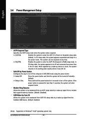
... enter suspend mode. English 2-6 Power Management Setup CMOS Setup Utility-Copyright (C) 1984-2007 Award Software Power Management Setup ACPI Suspend Type Soft-Off by Power button Modem Ring Resume USB Wake Up from S3 PME Event Wake Up HPET Support (Note) Power On By Mouse Power On By Keyboard x KB Power ON Password AC Back Function Power-On by a wake-up signal from the installed USB device. (Default: Enabled) (Note) Supported on Suspend) sleep state (default). Enables the system to enter the ACPI S3 (Suspend to enter the ACPI...
... enter suspend mode. English 2-6 Power Management Setup CMOS Setup Utility-Copyright (C) 1984-2007 Award Software Power Management Setup ACPI Suspend Type Soft-Off by Power button Modem Ring Resume USB Wake Up from S3 PME Event Wake Up HPET Support (Note) Power On By Mouse Power On By Keyboard x KB Power ON Password AC Back Function Power-On by a wake-up signal from the installed USB device. (Default: Enabled) (Note) Supported on Suspend) sleep state (default). Enables the system to enter the ACPI S3 (Suspend to enter the ACPI...

Manual
Page 49
... memory and reduce the useful life of the Northbridge and Southbridge. CPU Host Clock Control Enables or disables the control of CPU host clock. Auto (default) allows BIOS to 200 MHz. Important It is from 100 MHz to automatically adjust the CPU host frequency. BIOS Setup Normal Supplies the Northbridge/Sourthbridge voltage as required. (Default) +0.025V~+0.200V Increases the Northbridge/Sourthbridge voltage by 0.025V to boot. The adjustable range is for advanced users...
... memory and reduce the useful life of the Northbridge and Southbridge. CPU Host Clock Control Enables or disables the control of CPU host clock. Auto (default) allows BIOS to 200 MHz. Important It is from 100 MHz to automatically adjust the CPU host frequency. BIOS Setup Normal Supplies the Northbridge/Sourthbridge voltage as required. (Default) +0.025V~+0.200V Increases the Northbridge/Sourthbridge voltage by 0.025V to boot. The adjustable range is for advanced users...
Manual
Page 53
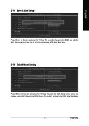
... press the key. BIOS Setup This saves the changes to the CMOS and exits the BIOS Setup program. English 2-13 Save & Exit Setup CMOS Setup Utility-Copyright (C) 1984-2007 Award Software ` Standard CMOS Features Load Fail-Safe Defaults ` Advanced BIOS Features Load Optimized Defaults ` Integrated Peripherals Set Supervisor Password ` Power Management Setup Save to CMOS and EXIT (SYe/tNU)?seYr Password ` PnP/PCI Configurations Save & Exit Setup ` PC Health Status Exit Without Saving ` MB Intelligent Tweaker(M.I .T.) F8: Q-Flash Load Fail-Safe Defaults Load Optimized Defaults Set...
... press the key. BIOS Setup This saves the changes to the CMOS and exits the BIOS Setup program. English 2-13 Save & Exit Setup CMOS Setup Utility-Copyright (C) 1984-2007 Award Software ` Standard CMOS Features Load Fail-Safe Defaults ` Advanced BIOS Features Load Optimized Defaults ` Integrated Peripherals Set Supervisor Password ` Power Management Setup Save to CMOS and EXIT (SYe/tNU)?seYr Password ` PnP/PCI Configurations Save & Exit Setup ` PC Health Status Exit Without Saving ` MB Intelligent Tweaker(M.I .T.) F8: Q-Flash Load Fail-Safe Defaults Load Optimized Defaults Set...
Manual
Page 71
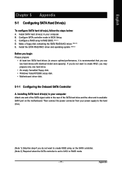
...supply to the hard drive. (Note 1) Skip this step if you do not want to AHCI or RAID mode. - 71 - Configure SATA controller mode in RAID BIOS. (Note 1) D. Make a floppy disk containing the SATA RAID/AHCI driver. (Note 2) E. Then connect the power connector from your computer. B. Appendix C . Install SATA hard drive(s) in your computer Attach one hard drive. • An empty formatted floppy disk. • Windows Vista/XP/2000 setup disk. • Motherboard driver disk. 5-1-1 Configuring the Onboard SATA Controller A. If you use two hard drives with identical model...
...supply to the hard drive. (Note 1) Skip this step if you do not want to AHCI or RAID mode. - 71 - Configure SATA controller mode in RAID BIOS. (Note 1) D. Make a floppy disk containing the SATA RAID/AHCI driver. (Note 2) E. Then connect the power connector from your computer. B. Appendix C . Install SATA hard drive(s) in your computer Attach one hard drive. • An empty formatted floppy disk. • Windows Vista/XP/2000 setup disk. • Motherboard driver disk. 5-1-1 Configuring the Onboard SATA Controller A. If you use two hard drives with identical model...
Manual
Page 79
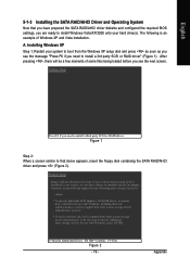
... prepared the SATA RAID/AHCI driver diskette and configured the required BIOS settings, you have chosen to specify additional mass storage devices for use with Windows, including those for use with Windows, press ENTER. Appendix The following mass storage devices(s) * To specify additional SCSI adapters, CD-ROM drives, or special disk controllers for which you have any device support disks from the Windows XP setup disk and press as soon as you see the next screen. Windows Setup Press...
... prepared the SATA RAID/AHCI driver diskette and configured the required BIOS settings, you have chosen to specify additional mass storage devices for use with Windows, including those for use with Windows, press ENTER. Appendix The following mass storage devices(s) * To specify additional SCSI adapters, CD-ROM drives, or special disk controllers for which you have any device support disks from the Windows XP setup disk and press as soon as you see the next screen. Windows Setup Press...

Manual
Page 96
... you identify possible computer problems. (For reference only.) 1 short: System boots successfully 2 short: CMOS setting error 1 long, 1 short: Memory or motherboard error 1 long, 2 short: Monitor or graphics card error 1 long, 3 short: Keyboard error 1 long, 9 short: BIOS ROM error Continuous long beeps: Graphics card not inserted properly Continuous short beeps: Power error GA-MA69G-S3H Motherboard - 96 - A: Some motherboard provides a small amount of my keyboard/optical mouse still on after the computer shuts down ? If your board doesn't have turned my speaker to the maximum volume...
... you identify possible computer problems. (For reference only.) 1 short: System boots successfully 2 short: CMOS setting error 1 long, 1 short: Memory or motherboard error 1 long, 2 short: Monitor or graphics card error 1 long, 3 short: Keyboard error 1 long, 9 short: BIOS ROM error Continuous long beeps: Graphics card not inserted properly Continuous short beeps: Power error GA-MA69G-S3H Motherboard - 96 - A: Some motherboard provides a small amount of my keyboard/optical mouse still on after the computer shuts down ? If your board doesn't have turned my speaker to the maximum volume...


