Manual
Page 3
... the information on/from the Support\Motherboard\Technology Guide page on your motherboard revision before updating motherboard BIOS, drivers, or when looking for technical information. No part of this manual is protected by GIGABYTE without GIGABYTE's prior written permission. All rights reserved. Disclaimer Information in this manual may be reproduced, copied, translated, transmitted...
... the information on/from the Support\Motherboard\Technology Guide page on your motherboard revision before updating motherboard BIOS, drivers, or when looking for technical information. No part of this manual is protected by GIGABYTE without GIGABYTE's prior written permission. All rights reserved. Disclaimer Information in this manual may be reproduced, copied, translated, transmitted...
Manual
Page 4
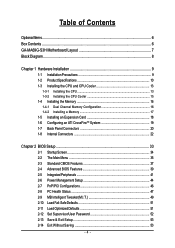
Table of Contents OptionalItems ...6 Box Contents ...6 GA-MA69G-S3H Motherboard Layout 7 Block Diagram ...8 Chapter 1 Hardware Installation 9 1-1 Installation Precautions 9 1-2 Product Specifications 10 1-3 Installing the CPU and CPU Cooler 13 1-3-1...18 1-6 Configuring an ATI CrossFireTM System 19 1-7 Back Panel Connectors 20 1-8 Internal Connectors 22 Chapter 2 BIOS Setup 33 2-1 Startup Screen 34 2-2 The Main Menu 35 2-3 Standard CMOS Features 37 2-4 Advanced BIOS Features 39 2-5 IntegratedPeripherals 41 2-6 Power Management Setup 44 2-7 PnP/PCI Configurations 46 2-8 PC Health ...
Table of Contents OptionalItems ...6 Box Contents ...6 GA-MA69G-S3H Motherboard Layout 7 Block Diagram ...8 Chapter 1 Hardware Installation 9 1-1 Installation Precautions 9 1-2 Product Specifications 10 1-3 Installing the CPU and CPU Cooler 13 1-3-1...18 1-6 Configuring an ATI CrossFireTM System 19 1-7 Back Panel Connectors 20 1-8 Internal Connectors 22 Chapter 2 BIOS Setup 33 2-1 Startup Screen 34 2-2 The Main Menu 35 2-3 Standard CMOS Features 37 2-4 Advanced BIOS Features 39 2-5 IntegratedPeripherals 41 2-6 Power Management Setup 44 2-7 PnP/PCI Configurations 46 2-8 PC Health ...
Manual
Page 5
... 56 3-3 Driver CD Information 56 3-4 Hardware Information 57 3-5 Contact Us ...57 Chapter 4 Unique Features 59 4-1 Xpress Recovery2 59 4-2 BIOS Update Utilities 64 4-2-1 Updating the BIOS with the Q-Flash Utility 64 4-2-2 Updating the BIOS with the @BIOS Utility 67 4-3 EasyTune 5 ...69 4-4 Windows Vista ReadyBoost 70 Chapter 5 Appendix ...71 5-1 Configuring SATA Hard Drive(s 71 5-1-1 Configuring the...
... 56 3-3 Driver CD Information 56 3-4 Hardware Information 57 3-5 Contact Us ...57 Chapter 4 Unique Features 59 4-1 Xpress Recovery2 59 4-2 BIOS Update Utilities 64 4-2-1 Updating the BIOS with the Q-Flash Utility 64 4-2-2 Updating the BIOS with the @BIOS Utility 67 4-3 EasyTune 5 ...69 4-4 Windows Vista ReadyBoost 70 Chapter 5 Appendix ...71 5-1 Configuring SATA Hard Drive(s 71 5-1-1 Configuring the...
Manual
Page 7
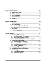
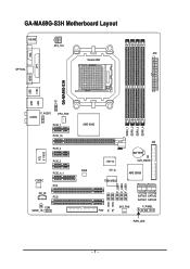
GA-MA69G-S3H Motherboard Layout KB_MS ATX_12V ATX Socket AM2 VGA LPT OPTICAL HDMI GA-MA69G-S3H 1394 USB USB LAN TV F_AUDIO AUDIO CPU_FAN PCIE_1 PCIE_16 PCIE_2 RTL 8110SC PCIE_3 CODEC CD_IN PCIE_4_1 PCI1 PCI2 COM SPDIF_IO AMD 690G DDRII_1 DDRII_2 DDRII_3 DDRII_4 IDE IT8716 BATTERY CLR_CMOS BIOS CI AMD SB600 TSB43AB23 F_USB1 F_USB2 F_USB3 F1_1394 F2_1394 SATAII3 SATAII2 SATAII1 SATAII0 SYS_FAN F_PANEL FDD PWR_LED - 7 -
GA-MA69G-S3H Motherboard Layout KB_MS ATX_12V ATX Socket AM2 VGA LPT OPTICAL HDMI GA-MA69G-S3H 1394 USB USB LAN TV F_AUDIO AUDIO CPU_FAN PCIE_1 PCIE_16 PCIE_2 RTL 8110SC PCIE_3 CODEC CD_IN PCIE_4_1 PCI1 PCI2 COM SPDIF_IO AMD 690G DDRII_1 DDRII_2 DDRII_3 DDRII_4 IDE IT8716 BATTERY CLR_CMOS BIOS CI AMD SB600 TSB43AB23 F_USB1 F_USB2 F_USB3 F1_1394 F2_1394 SATAII3 SATAII2 SATAII1 SATAII0 SYS_FAN F_PANEL FDD PWR_LED - 7 -
Manual
Page 8
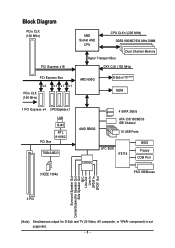
... PCI Bus RTL 8110SC TSB43AB23 3 IEEE 1394a AMD SB600 4 SATA 3Gb/s ATA-133/100/66/33 IDE Channel 10 USB Ports CODEC LPC BUS IT8716 BIOS Floppy COM Port PS/2 KB/Mouse Surround Speaker Out Center/Subwoofer Speaker Out Side Speaker Out MIC Line-Out Line-In SPDIF In SPDIF Out...
... PCI Bus RTL 8110SC TSB43AB23 3 IEEE 1394a AMD SB600 4 SATA 3Gb/s ATA-133/100/66/33 IDE Channel 10 USB Ports CODEC LPC BUS IT8716 BIOS Floppy COM Port PS/2 KB/Mouse Surround Speaker Out Center/Subwoofer Speaker Out Side Speaker Out MIC Line-Out Line-In SPDIF In SPDIF Out...
Manual
Page 11
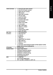
... temperature detection Š CPU/System fan speed detection Š CPU/System overheating warning Š CPU/System fan fail warning Š CPU fan speed control (Note 2) BIOS Š 1 x 4 Mbit flash Š Use of licensed AWARD...
... temperature detection Š CPU/System fan speed detection Š CPU/System overheating warning Š CPU/System fan fail warning Š CPU fan speed control (Note 2) BIOS Š 1 x 4 Mbit flash Š Use of licensed AWARD...
Manual
Page 12
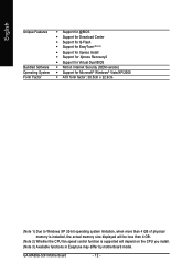
... Center Š Support for Q-Flash Š Support for EasyTune (Note 3) Š Support for Xpress Install Š Support for Xpress Recovery2 Š Support for Virtual Dual BIOS Š Norton Internet Security (OEM version) Š Support for Microsoft® Windows® Vista/XP/2000 Š ATX form factor; 30.5cm x 22.9cm (Note... the CPU fan speed control function is supported will depend on the CPU you install. (Note 3) Available functions in Easytune may differ by motherboard model. GA-MA69G-S3H Motherboard - 12 -
... Center Š Support for Q-Flash Š Support for EasyTune (Note 3) Š Support for Xpress Install Š Support for Xpress Recovery2 Š Support for Virtual Dual BIOS Š Norton Internet Security (OEM version) Š Support for Microsoft® Windows® Vista/XP/2000 Š ATX form factor; 30.5cm x 22.9cm (Note... the CPU fan speed control function is supported will depend on the CPU you install. (Note 3) Available functions in Easytune may differ by motherboard model. GA-MA69G-S3H Motherboard - 12 -
Manual
Page 16
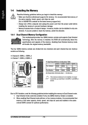
...be installed, it is installed, the BIOS will double the original memory bandwidth. ...Dual Channel Memory Configuration This motherboard provides four DDR2 memory sockets and supports Dual Channel Technology. GA-MA69G-S3H Motherboard - 16 - Dual Channel mode cannot be used and installed in Dual Channel mode....will automatically detect the specifications and capacity of the same capacity, brand, speed, and chips be used . (Go to GIGABYTE's website for optimum performance. English 1-4 Installing the Memory Read the following guidelines before you begin to prevent hardware damage....
...be installed, it is installed, the BIOS will double the original memory bandwidth. ...Dual Channel Memory Configuration This motherboard provides four DDR2 memory sockets and supports Dual Channel Technology. GA-MA69G-S3H Motherboard - 16 - Dual Channel mode cannot be used and installed in Dual Channel mode....will automatically detect the specifications and capacity of the same capacity, brand, speed, and chips be used . (Go to GIGABYTE's website for optimum performance. English 1-4 Installing the Memory Read the following guidelines before you begin to prevent hardware damage....
Manual
Page 18
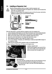
... are completely inserted into the PCI Express x16 slot. Turn on the back of the PCI Express x16 slot to prevent hardware damage. GA-MA69G-S3H Motherboard - 18 - Carefully read the manual that supports your expansion card(s). 7. Align the card with your computer. Remove the metal ...motherboard supports the expansion card. Secure the card's metal bracket to make any required BIOS changes for your card. After installing all expansion cards, replace the chassis cover(s). 6. If necessary, go to BIOS Setup to the chassis back panel with the expansion card in the slot. 3. ...
... are completely inserted into the PCI Express x16 slot. Turn on the back of the PCI Express x16 slot to prevent hardware damage. GA-MA69G-S3H Motherboard - 18 - Carefully read the manual that supports your expansion card(s). 7. Align the card with your computer. Remove the metal ...motherboard supports the expansion card. Secure the card's metal bracket to make any required BIOS changes for your card. After installing all expansion cards, replace the chassis cover(s). 6. If necessary, go to BIOS Setup to the chassis back panel with the expansion card in the slot. 3. ...
Manual
Page 19
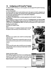
... Control Center, enter the CrossFire menu and select the Enable CrossFire checkbox to fully support an CrossFire configuration and other components in BIOS Setup to PEG first. (Start your system with your graphics cards for more information about enabling CrossFire.) Step 3: Connect your ...LCD monitor cable to the DVI-I port on the graphics card on your operating system, access the ATI CATALYST Control Center. BIOS Settings: Before configuring your system. Refer to the manual that is currrently supported by graphics cards. English 1-6 Configuring an ATI CrossFireTM System...
... Control Center, enter the CrossFire menu and select the Enable CrossFire checkbox to fully support an CrossFire configuration and other components in BIOS Setup to PEG first. (Start your system with your graphics cards for more information about enabling CrossFire.) Step 3: Connect your ...LCD monitor cable to the DVI-I port on the graphics card on your operating system, access the ATI CATALYST Control Center. BIOS Settings: Before configuring your system. Refer to the manual that is currrently supported by graphics cards. English 1-6 Configuring an ATI CrossFireTM System...
Manual
Page 26
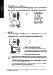
... (+) and the negative side (-) of the battery holder, making them short for one . Danger of explosion if the battery is in S1 sleep state. GA-MA69G-S3H Motherboard - 26 - Pin No. You may be used to connect a system power LED on when the system is operating. The LED is off when ... by removing the battery: 1. Definition 1 MPD+ 2 MPD- 1 3 MPD- Replace the battery. 4. The LED is on the chassis to keep the values (such as BIOS configurations, date, and time information) in the CMOS when the computer is in S3/S4 sleep state or powered off your computer. • Always turn...
... (+) and the negative side (-) of the battery holder, making them short for one . Danger of explosion if the battery is in S1 sleep state. GA-MA69G-S3H Motherboard - 26 - Pin No. You may be used to connect a system power LED on when the system is operating. The LED is off when ... by removing the battery: 1. Definition 1 MPD+ 2 MPD- 1 3 MPD- Replace the battery. 4. The LED is on the chassis to keep the values (such as BIOS configurations, date, and time information) in the CMOS when the computer is in S3/S4 sleep state or powered off your computer. • Always turn...
Manual
Page 27
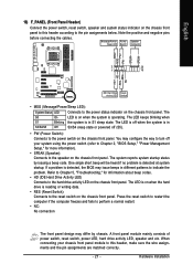
...HD+ HD- You may issue beeps in different patterns to indicate the problem. When connecting your system using the power switch (refer to Chapter 2, "BIOS Setup," "Power Management Setup," for information about beep codes. • HD (IDE Hard Drive Activity LED) Connects to the power status indicator on...panel to this header, make sure the wire assignments and the pin assignments are matched correctly. - 27 - If a problem is detected, the BIOS may configure the way to turn off (S5). • PW (Power Switch): Connects to this header according to the speaker on the chassis front...
...HD+ HD- You may issue beeps in different patterns to indicate the problem. When connecting your system using the power switch (refer to Chapter 2, "BIOS Setup," "Power Management Setup," for information about beep codes. • HD (IDE Hard Drive Activity LED) Connects to the power status indicator on...panel to this header, make sure the wire assignments and the pin assignments are matched correctly. - 27 - If a problem is detected, the BIOS may configure the way to turn off (S5). • PW (Power Switch): Connects to this header according to the speaker on the chassis front...
Manual
Page 31
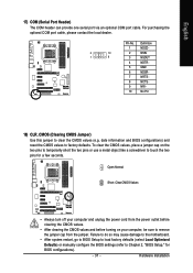
...pins to temporarily short the two pins or use a metal object like a screwdriver to touch the two pins for BIOS configurations). - 31 - Hardware Installation date information and BIOS configurations) and reset the CMOS values to remove the jumper cap from the jumper. Pin No. To clear the ...Failure to do so may cause damage to the motherboard. • After system restart, go to BIOS Setup to load factory defaults (select Load Optimized Defaults) or manually configure the BIOS settings (refer to clear the CMOS values (e.g. For purchasing the optional COM port cable, please contact ...
...pins to temporarily short the two pins or use a metal object like a screwdriver to touch the two pins for BIOS configurations). - 31 - Hardware Installation date information and BIOS configurations) and reset the CMOS values to remove the jumper cap from the jumper. Pin No. To clear the ...Failure to do so may cause damage to the motherboard. • After system restart, go to BIOS Setup to load factory defaults (select Load Optimized Defaults) or manually configure the BIOS settings (refer to clear the CMOS values (e.g. For purchasing the optional COM port cable, please contact ...
Manual
Page 33
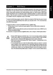
... values.) - 33 - If this chapter or introductions of BIOS from the Internet and updates the BIOS. To upgrade the BIOS, use either the GIGABYTE Q-Flash or @BIOS utility. • Q-Flash allows the user to quickly and easily upgrade or back up BIOS without entering the operating system. • @BIOS is recommended that searches and downloads the latest...
... values.) - 33 - If this chapter or introductions of BIOS from the Internet and updates the BIOS. To upgrade the BIOS, use either the GIGABYTE Q-Flash or @BIOS utility. • Q-Flash allows the user to quickly and easily upgrade or back up BIOS without entering the operating system. • @BIOS is recommended that searches and downloads the latest...
Manual
Page 34
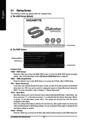
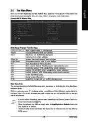
... 04/27/2007-RS690G-SB600-6A669G02C-00 Function Keys Function Keys: : POST Screen Press the key to show the BIOS POST screen at system startup, refer to accept. To show the BIOS POST screen. GA-MA69G-S3H Motherboard - 34 - For more information, refer to Chapter 4, "Xpress Recovery2." : Boot Menu Boot Menu allows you have ever...
... 04/27/2007-RS690G-SB600-6A669G02C-00 Function Keys Function Keys: : POST Screen Press the key to show the BIOS POST screen at system startup, refer to accept. To show the BIOS POST screen. GA-MA69G-S3H Motherboard - 34 - For more information, refer to Chapter 4, "Xpress Recovery2." : Boot Menu Boot Menu allows you have ever...
Manual
Page 35
... Item F10: Save & Exit Setup Time, Date, Hard Disk Type... BIOS Setup Submenu Help While in a submenu, press to display a help screen. BIOS Setup Program Function Keys Move the selection bar to select an item Execute ...command or enter the submenu Main Menu: Exit the BIOS Setup program Submenus: Exit current submenu Increase the numeric value or make changes Decrease ...of the submenu. • If you do not find the settings you enter the BIOS Setup program, the Main Menu (as usual, select the Load Optimized Defaults item to set your system ...
... Item F10: Save & Exit Setup Time, Date, Hard Disk Type... BIOS Setup Submenu Help While in a submenu, press to display a help screen. BIOS Setup Program Function Keys Move the selection bar to select an item Execute ...command or enter the submenu Main Menu: Exit the BIOS Setup program Submenus: Exit current submenu Increase the numeric value or make changes Decrease ...of the submenu. • If you do not find the settings you enter the BIOS Setup program, the Main Menu (as usual, select the Load Optimized Defaults item to set your system ...

Manual
Page 36
...you to make changes. „ Save & Exit Setup Save all the changes made in the BIOS Setup program to the CMOS and exit BIOS Setup. (Pressing can also carry out this task.) GA-MA69G-S3H Motherboard - 36 - English „ Standard CMOS Features Use this menu to configure the system...settings for optimal-performance system operations. „ Set Supervisor Password Change, set , or disable password. Pressing to the confirmation message will exit BIOS Setup. (Pressing can also carry out this task.) „ Exit Without Saving Abandon all the power-saving functions. „ PnP/PCI ...
...you to make changes. „ Save & Exit Setup Save all the changes made in the BIOS Setup program to the CMOS and exit BIOS Setup. (Pressing can also carry out this task.) GA-MA69G-S3H Motherboard - 36 - English „ Standard CMOS Features Use this menu to configure the system...settings for optimal-performance system operations. „ Set Supervisor Password Change, set , or disable password. Pressing to the confirmation message will exit BIOS Setup. (Pressing can also carry out this task.) „ Exit Without Saving Abandon all the power-saving functions. „ PnP/PCI ...
Manual
Page 37
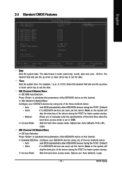
... key to set the date. IDE Channel 0 Master/Slave Configure your IDE/SATA devices using one of the two methods below : • Auto Lets BIOS automatically detect IDE/SATA devices during the POST. (Default) • None If no IDE/SATA devices are used , set to autodetect the parameters of ...Sets the hard drive access mode. Extended IDE Drive Configure your IDE/SATA devices by using one of the three methods below : • Auto Lets BIOS automatically detect IDE/SATA devices during the POST. (Default) • None If no IDE/SATA devices are used , set this item to None so...
... key to set the date. IDE Channel 0 Master/Slave Configure your IDE/SATA devices using one of the two methods below : • Auto Lets BIOS automatically detect IDE/SATA devices during the POST. (Default) • None If no IDE/SATA devices are used , set to autodetect the parameters of ...Sets the hard drive access mode. Extended IDE Drive Configure your IDE/SATA devices by using one of the three methods below : • Auto Lets BIOS automatically detect IDE/SATA devices during the POST. (Default) • None If no IDE/SATA devices are used , set this item to None so...
Manual
Page 38
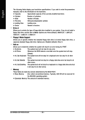
...Head Number of the currently installed hard drive. Halt on the hard drive. GA-MA69G-S3H Motherboard - 38 - English The following fields display your system. Landing Zone Landing zone. Options are determined by the BIOS POST. No Errors All Errors The system boot will not stop for a... installed in your hard drive specifications. Precomp Write precompensation cylinder. Drive A Allows you to selects the type of cylinders. Whenever the BIOS detects a non-fatal error the system boot will stop. (Default) All, But Keyboard The system boot will stop for the MS...
...Head Number of the currently installed hard drive. Halt on the hard drive. GA-MA69G-S3H Motherboard - 38 - English The following fields display your system. Landing Zone Landing zone. Options are determined by the BIOS POST. No Errors All Errors The system boot will not stop for a... installed in your hard drive specifications. Precomp Write precompensation cylinder. Drive A Allows you to selects the type of cylinders. Whenever the BIOS detects a non-fatal error the system boot will stop. (Default) All, But Keyboard The system boot will stop for the MS...
Manual
Page 39
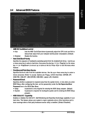
... power consumption. (Default) Disable this item, set the password(s) under the Set Supervisor/User Password item in the BIOS Main Menu. BIOS Setup After configuring this function. Capability Away Mode Full Screen LOGO Show Init Display First x Surroundview Internal Graphics Mode ... select a device and press to issue warnings when a third party hardware monitor utility is required for booting the system and for entering the BIOS Setup program. (Default) System A password is installed. (Default: Disabled) - 39 - HDD S.M.A.R.T. Capability Enables or disables the S.M.A.R.T. (...
... power consumption. (Default) Disable this item, set the password(s) under the Set Supervisor/User Password item in the BIOS Main Menu. BIOS Setup After configuring this function. Capability Away Mode Full Screen LOGO Show Init Display First x Surroundview Internal Graphics Mode ... select a device and press to issue warnings when a third party hardware monitor utility is required for booting the system and for entering the BIOS Setup program. (Default) System A password is installed. (Default: Disabled) - 39 - HDD S.M.A.R.T. Capability Enables or disables the S.M.A.R.T. (...


