Manual
Page 1
GA-MA69G-S3H AM2 socket motherboard for AMD AthlonTM 64 FX processor/ AMD AthlonTM 64 X2 Dual-Core processor/ AMD AthlonTM 64 processor/AMD SempronTM processor User's Manual Rev. 1002 12ME-MA69GS3H-1002R * The WEEE marking on the product indicates this product must not be disposed of with user's other household waste and must be handed over to a designated collection point for the recycling of waste electrical and electronic equipment!! * The WEEE marking applies only in European Union's member states.
GA-MA69G-S3H AM2 socket motherboard for AMD AthlonTM 64 FX processor/ AMD AthlonTM 64 X2 Dual-Core processor/ AMD AthlonTM 64 processor/AMD SempronTM processor User's Manual Rev. 1002 12ME-MA69GS3H-1002R * The WEEE marking on the product indicates this product must not be disposed of with user's other household waste and must be handed over to a designated collection point for the recycling of waste electrical and electronic equipment!! * The WEEE marking applies only in European Union's member states.
Manual
Page 3
.... The trademarks mentioned in any form or by GIGABYTE without GIGABYTE's prior written permission. is the property of the motherboard is exclusively licensed to use GIGABYTE's unique features, read the User's Manual. „ For instructions on how to GIGABYTE UNITED INC. GIGABYTE UNITED INC. No part of GIGABYTE branded motherboards. Copyright © 2007 GIGA-BYTE TECHNOLOGY CO., LTD...
.... The trademarks mentioned in any form or by GIGABYTE without GIGABYTE's prior written permission. is the property of the motherboard is exclusively licensed to use GIGABYTE's unique features, read the User's Manual. „ For instructions on how to GIGABYTE UNITED INC. GIGABYTE UNITED INC. No part of GIGABYTE branded motherboards. Copyright © 2007 GIGA-BYTE TECHNOLOGY CO., LTD...
Manual
Page 4
Table of Contents OptionalItems ...6 Box Contents ...6 GA-MA69G-S3H Motherboard Layout 7 Block Diagram ...8 Chapter 1 Hardware Installation 9 1-1 Installation Precautions 9 1-2 Product Specifications 10 1-3 Installing the CPU and CPU Cooler 13 1-3-1 Installing the CPU 13 1-3-2 Installing the CPU ...
Table of Contents OptionalItems ...6 Box Contents ...6 GA-MA69G-S3H Motherboard Layout 7 Block Diagram ...8 Chapter 1 Hardware Installation 9 1-1 Installation Precautions 9 1-2 Product Specifications 10 1-3 Installing the CPU and CPU Cooler 13 1-3-1 Installing the CPU 13 1-3-2 Installing the CPU ...
Manual
Page 6
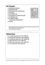
Box Contents GA-MA69G-S3H motherboard Motherboard driver disk Motherboard driver disk (For Windows Vista) User's Manual Quick Installation Guide One IDE cable and one floppy disk drive cable Two SATA 3Gb/s cables One HDMI-to-DVI adapter (This motherboard only supports DVI-D) I/O Shield • The box contents above are subject to change without notice. • The motherboard image...
Box Contents GA-MA69G-S3H motherboard Motherboard driver disk Motherboard driver disk (For Windows Vista) User's Manual Quick Installation Guide One IDE cable and one floppy disk drive cable Two SATA 3Gb/s cables One HDMI-to-DVI adapter (This motherboard only supports DVI-D) I/O Shield • The box contents above are subject to change without notice. • The motherboard image...
Manual
Page 7
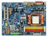
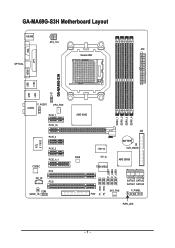
GA-MA69G-S3H Motherboard Layout KB_MS ATX_12V ATX Socket AM2 VGA LPT OPTICAL HDMI GA-MA69G-S3H 1394 USB USB LAN TV F_AUDIO AUDIO CPU_FAN PCIE_1 PCIE_16 PCIE_2 RTL 8110SC PCIE_3 CODEC CD_IN PCIE_4_1 PCI1 PCI2 COM SPDIF_IO AMD 690G DDRII_1 DDRII_2 DDRII_3 DDRII_4 IDE IT8716 BATTERY CLR_CMOS BIOS CI AMD SB600 TSB43AB23 F_USB1 F_USB2 F_USB3 F1_1394 F2_1394 SATAII3 SATAII2 SATAII1 SATAII0 SYS_FAN F_PANEL FDD PWR_LED - 7 -
GA-MA69G-S3H Motherboard Layout KB_MS ATX_12V ATX Socket AM2 VGA LPT OPTICAL HDMI GA-MA69G-S3H 1394 USB USB LAN TV F_AUDIO AUDIO CPU_FAN PCIE_1 PCIE_16 PCIE_2 RTL 8110SC PCIE_3 CODEC CD_IN PCIE_4_1 PCI1 PCI2 COM SPDIF_IO AMD 690G DDRII_1 DDRII_2 DDRII_3 DDRII_4 IDE IT8716 BATTERY CLR_CMOS BIOS CI AMD SB600 TSB43AB23 F_USB1 F_USB2 F_USB3 F1_1394 F2_1394 SATAII3 SATAII2 SATAII1 SATAII0 SYS_FAN F_PANEL FDD PWR_LED - 7 -
Manual
Page 9
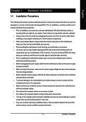
...connectors. • It is best to wear an electrostatic discharge (ESD) wrist strap when handling electronic components such as a motherboard, CPU or memory. Hardware Installation These stickers are required for warranty validation. • Always remove the AC power by unplugging...installation process can become damaged as a result of electrostatic discharge (ESD). English Chapter 1 Hardware Installation 1-1 Installation Precautions The motherboard contains numerous delicate electronic circuits and components which can lead to damage to system components as well as physical harm to the ...
...connectors. • It is best to wear an electrostatic discharge (ESD) wrist strap when handling electronic components such as a motherboard, CPU or memory. Hardware Installation These stickers are required for warranty validation. • Always remove the AC power by unplugging...installation process can become damaged as a result of electrostatic discharge (ESD). English Chapter 1 Hardware Installation 1-1 Installation Precautions The motherboard contains numerous delicate electronic circuits and components which can lead to damage to system components as well as physical harm to the ...
Manual
Page 10
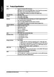
... 64 processor/AMD SempronTM processor (Go to GIGABYTE's website for the latest CPU support list.) Š 2000 MHz FSB Š North Bridge: AMD 690G Š South Bridge: AMD SB600 Š 4 x 1.8V DDR2 DIMM sockets supporting up to the internal USB headers) GA-MA69G-S3H Motherboard - 10 - TSB43AB23 chip Š Up...16 GB of system memory (Note 1) Š Dual channel memory architecture Š Support for DDR2 800/667/533 MHz memory modules (Go to GIGABYTE's website for the latest memory support list.) Š Integrated in the South Bridge Š Up to 10 USB 2.0/1.1 ports (4 on the back ...
... 64 processor/AMD SempronTM processor (Go to GIGABYTE's website for the latest CPU support list.) Š 2000 MHz FSB Š North Bridge: AMD 690G Š South Bridge: AMD SB600 Š 4 x 1.8V DDR2 DIMM sockets supporting up to the internal USB headers) GA-MA69G-S3H Motherboard - 10 - TSB43AB23 chip Š Up...16 GB of system memory (Note 1) Š Dual channel memory architecture Š Support for DDR2 800/667/533 MHz memory modules (Go to GIGABYTE's website for the latest memory support list.) Š Integrated in the South Bridge Š Up to 10 USB 2.0/1.1 ports (4 on the back ...
Manual
Page 12
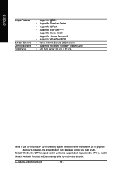
GA-MA69G-S3H Motherboard - 12 - English Unique Features Bundled Software Operating System Form Factor Š Support for @BIOS Š Support for Download Center Š Support for Q-Flash Š Support .... (Note 2) Whether the CPU fan speed control function is supported will depend on the CPU you install. (Note 3) Available functions in Easytune may differ by motherboard model.
GA-MA69G-S3H Motherboard - 12 - English Unique Features Bundled Software Operating System Form Factor Š Support for @BIOS Š Support for Download Center Š Support for Q-Flash Š Support .... (Note 2) Whether the CPU fan speed control function is supported will depend on the CPU you install. (Note 3) Available functions in Easytune may differ by motherboard model.
Manual
Page 13
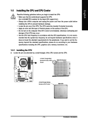
mended that the motherboard supports the CPU. (Go to GIGABYTE's website for the peripherals. Hardware Installation The CPU cannot be set the frequency beyond the standard specifications, please do so according to your hardware specifications ...
mended that the motherboard supports the CPU. (Go to GIGABYTE's website for the peripherals. Hardware Installation The CPU cannot be set the frequency beyond the standard specifications, please do so according to your hardware specifications ...
Manual
Page 14
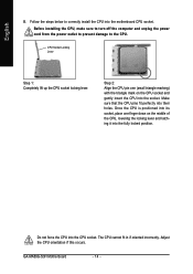
... socket. CPU Socket Locking Lever Step 1: Completely lift up the CPU socket locking lever. Do not force the CPU into their holes. GA-MA69G-S3H Motherboard - 14 - Step 2: Align the CPU pin one finger down on the CPU socket and gently insert the CPU into the fully locked position. Adjust the ...
... socket. CPU Socket Locking Lever Step 1: Completely lift up the CPU socket locking lever. Do not force the CPU into their holes. GA-MA69G-S3H Motherboard - 14 - Step 2: Align the CPU pin one finger down on the CPU socket and gently insert the CPU into the fully locked position. Adjust the ...
Manual
Page 15
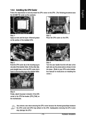
... 15 - English 1-3-2 Installing the CPU Cooler Follow the steps below to correctly install the CPU cooler on the CPU. (The following procedure uses the GIGABYTE cooler as the picture above shows) to lock into place. (Refer to your CPU cooler installation manual for instructions on installing the cooler.) Step 5: ...Finally, attach the power connector of the CPU cooler to the CPU fan header (CPU_FAN) on the motherboard. On the other side, push straight down on the the CPU cooler clip to hook it to the mounting lug on the CPU. Step 3:...
... 15 - English 1-3-2 Installing the CPU Cooler Follow the steps below to correctly install the CPU cooler on the CPU. (The following procedure uses the GIGABYTE cooler as the picture above shows) to lock into place. (Refer to your CPU cooler installation manual for instructions on installing the cooler.) Step 5: ...Finally, attach the power connector of the CPU cooler to the CPU fan header (CPU_FAN) on the motherboard. On the other side, push straight down on the the CPU cooler clip to hook it to the mounting lug on the CPU. Step 3:...
Manual
Page 16
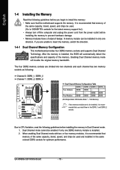
... four memory modules, it is recommended that memory of the same capacity, brand, speed, and chips be used . (Go to GIGABYTE's website for optimum performance. It is recommended that you install them in the DDRII_1 and DDRII_2 sockets. Enabling Dual Channel memory mode ...1. The four DDR2 memory sockets are unable to insert the memory, switch the direction. 1-4-1 Dual Channel Memory Configuration This motherboard provides four DDR2 memory sockets and supports Dual Channel Technology. Dual Channel mode cannot be enabled if only one direction. GA-MA69G-S3H Motherboard - 16 -
... four memory modules, it is recommended that memory of the same capacity, brand, speed, and chips be used . (Go to GIGABYTE's website for optimum performance. It is recommended that you install them in the DDRII_1 and DDRII_2 sockets. Enabling Dual Channel memory mode ...1. The four DDR2 memory sockets are unable to insert the memory, switch the direction. 1-4-1 Dual Channel Memory Configuration This motherboard provides four DDR2 memory sockets and supports Dual Channel Technology. Dual Channel mode cannot be enabled if only one direction. GA-MA69G-S3H Motherboard - 16 -
Manual
Page 17
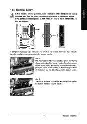
... , make sure to turn off the computer and unplug the power cord from the power outlet to prevent damage to install DDR2 DIMMs on this motherboard. Place the memory module on the left, place your memory modules in one direction. Hardware Installation Spread the retaining clips at both ends of the...
... , make sure to turn off the computer and unplug the power cord from the power outlet to prevent damage to install DDR2 DIMMs on this motherboard. Place the memory module on the left, place your memory modules in one direction. Hardware Installation Spread the retaining clips at both ends of the...
Manual
Page 18
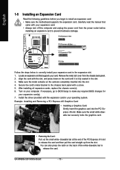
... the expansion card. You can also press the latch on the card are completely inserted into the PCI Express x16 slot. GA-MA69G-S3H Motherboard - 18 - After installing all expansion cards, replace the chassis cover(s). 6. If necessary, go to BIOS Setup to correctly install your expansion card(s). 7. Make sure the ...
... the expansion card. You can also press the latch on the card are completely inserted into the PCI Express x16 slot. GA-MA69G-S3H Motherboard - 18 - After installing all expansion cards, replace the chassis cover(s). 6. If necessary, go to BIOS Setup to correctly install your expansion card(s). 7. Make sure the ...
Manual
Page 20
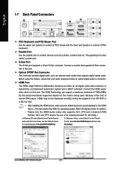
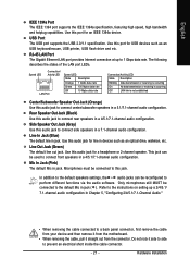
... connect devices such as a printer, scanner and etc. Because of the limit of 1920x1080p but the actual resolutions supported depend on the monitor being used. GA-MA69G-S3H Motherboard - 20 - English 1-7 Back Panel Connectors PS/2 Keyboard and PS/2 Mouse Port Use the upper port (green) to connect a PS/2 mouse and the lower port (purple...
... connect devices such as a printer, scanner and etc. Because of the limit of 1920x1080p but the actual resolutions supported depend on the monitor being used. GA-MA69G-S3H Motherboard - 20 - English 1-7 Back Panel Connectors PS/2 Keyboard and PS/2 Mouse Port Use the upper port (green) to connect a PS/2 mouse and the lower port (purple...
Manual
Page 21
... default line out jack. Microphones must be used to a back panel connector, first remove the cable from your device and then remove it from the motherboard. • When removing the cable, pull it side to side to this audio jack for an IEEE 1394a device. Hardware Installation English IEEE 1394a Port...
... default line out jack. Microphones must be used to a back panel connector, first remove the cable from your device and then remove it from the motherboard. • When removing the cable, pull it side to side to this audio jack for an IEEE 1394a device. Hardware Installation English IEEE 1394a Port...
Manual
Page 22
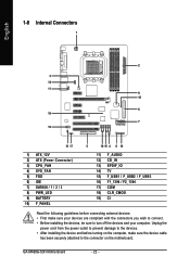
GA-MA69G-S3H Motherboard - 22 - English 1-8 Internal Connectors 1 2 3 14 11 9 18 6 19 7 12 13 17 1) ATX_12V 2) ATX (Power Connector) 3) CPU_FAN 4) SYS_FAN 5) FDD 6) IDE 7) SATAII0 / 1 / 2 / 3 8) PWR_LED 9) BATTERY 10) F_PANEL 5 16 ..., make sure your devices are compliant with the connectors you wish to connect. • Before installing the devices, be sure to the connector on the motherboard. Unplug the power cord from the power outlet to prevent damage to the devices. • After installing the device and before connecting external devices: •...
GA-MA69G-S3H Motherboard - 22 - English 1-8 Internal Connectors 1 2 3 14 11 9 18 6 19 7 12 13 17 1) ATX_12V 2) ATX (Power Connector) 3) CPU_FAN 4) SYS_FAN 5) FDD 6) IDE 7) SATAII0 / 1 / 2 / 3 8) PWR_LED 9) BATTERY 10) F_PANEL 5 16 ..., make sure your devices are compliant with the connectors you wish to connect. • Before installing the devices, be sure to the connector on the motherboard. Unplug the power cord from the power outlet to prevent damage to the devices. • After installing the device and before connecting external devices: •...
Manual
Page 23
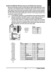
...connected, the computer will not start. • To meet expansion requirements, it is turned off and all the components on the motherboard. Do not insert the power supply cable into pins under the protective cover when using a 2x12 power supply, remove the protective ...cover from the main power connector on the motherboard. When using a 2x10 power supply. 4 2 3 1 ATX_12V ATX_12V: Pin No. 1 2 3 4 Definition GND GND +12V +12V 13 1 24 12 ATX ATX : Pin No. 1 2 3 4 5 ...
...connected, the computer will not start. • To meet expansion requirements, it is turned off and all the components on the motherboard. Do not insert the power supply cable into pins under the protective cover when using a 2x12 power supply, remove the protective ...cover from the main power connector on the motherboard. When using a 2x10 power supply. 4 2 3 1 ATX_12V ATX_12V: Pin No. 1 2 3 4 Definition GND GND +12V +12V 13 1 24 12 ATX ATX : Pin No. 1 2 3 4 5 ...
Manual
Page 24
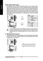
... your CPU and system from overheating. Do not place a jumper cap on the connector. 33 1 34 2 GA-MA69G-S3H Motherboard - 24 - A red power connector wire indicates a positive connection and requires a +12V voltage. English 3/4) CPU_FAN/SYS_FAN (Fan Headers) The motherboard has a 4-pin CPU fan header (CPU_FAN) and a 3-pin system fan header (SYS_FAN). Each fan header supplies...
... your CPU and system from overheating. Do not place a jumper cap on the connector. 33 1 34 2 GA-MA69G-S3H Motherboard - 24 - A red power connector wire indicates a positive connection and requires a +12V voltage. English 3/4) CPU_FAN/SYS_FAN (Fan Headers) The motherboard has a 4-pin CPU fan header (CPU_FAN) and a 3-pin system fan header (SYS_FAN). Each fan header supplies...
Manual
Page 26
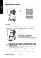
... off your computer and unplug the power cord. 2. The LED is on the chassis to indicate system power status. Pin No. Definition 1 MPD+ 2 MPD- 1 3 MPD- GA-MA69G-S3H Motherboard - 26 - The LED keeps blinking when the system is turned off your computer and unplug the power cord before replacing the battery. • Replace the...
... off your computer and unplug the power cord. 2. The LED is on the chassis to indicate system power status. Pin No. Definition 1 MPD+ 2 MPD- 1 3 MPD- GA-MA69G-S3H Motherboard - 26 - The LED keeps blinking when the system is turned off your computer and unplug the power cord before replacing the battery. • Replace the...


