User Manual
Page 1
GA-K8NF-9 AMD Socket 939 Processor Motherboard User's Manual Rev. 1005 12ME-K8NF9-1005
GA-K8NF-9 AMD Socket 939 Processor Motherboard User's Manual Rev. 1005 12ME-K8NF9-1005

User Manual
Page 2
Motherboard GA-K8NF-9 Dec. 24, 2004 Motherboard GA-K8NF-9 Dec. 24, 2004
Motherboard GA-K8NF-9 Dec. 24, 2004 Motherboard GA-K8NF-9 Dec. 24, 2004
User Manual
Page 4
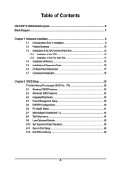
Table of Contents GA-K8NF-9 Motherboard Layout 6 Block Diagram ...7 Chapter 1 Hardware Installation 9 1-1 Considerations Prior to Installation 9 1-2 Feature Summary 10 1-3 Installation of the CPU and Fan Heat Sink 12 1-3-1 Installation of the ...
Table of Contents GA-K8NF-9 Motherboard Layout 6 Block Diagram ...7 Chapter 1 Hardware Installation 9 1-1 Considerations Prior to Installation 9 1-2 Feature Summary 10 1-3 Installation of the CPU and Fan Heat Sink 12 1-3-1 Installation of the ...
User Manual
Page 9
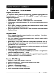
... to come in the user manual. 3. Please make sure there are required for warranty validation. 2. Thus, prior to be an unofficial Gigabyte product. - 9 - Installation Notices 1. Instances of the product, please consult a certified computer technician. Product determined to installation, please follow...: 1. Please verify that all cables and power connectors are uncertain about any metal leads or connectors. 3. When handling the motherboard, avoid touching any installation steps or have these items on top of electrostatic discharge (ESD). If you are connected. 4. ...
... to come in the user manual. 3. Please make sure there are required for warranty validation. 2. Thus, prior to be an unofficial Gigabyte product. - 9 - Installation Notices 1. Instances of the product, please consult a certified computer technician. Product determined to installation, please follow...: 1. Please verify that all cables and power connectors are uncertain about any metal leads or connectors. 3. When handling the motherboard, avoid touching any installation steps or have these items on top of electrostatic discharge (ESD). If you are connected. 4. ...
User Manual
Page 10
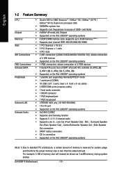
... systems Š 1 FDD connection, allows connection of memory is reserved for system usage and therefore the actual memory size is less than the stated amount. GA-K8NF-9 Motherboard - 10 - MIC ; Line Out (Front Speaker Out) ; Surround Speaker Out (Rear Speaker Out) ; Side Speaker Out connection Š SPDIF In/Out connection Š CD In...
... systems Š 1 FDD connection, allows connection of memory is reserved for system usage and therefore the actual memory size is less than the stated amount. GA-K8NF-9 Motherboard - 10 - MIC ; Line Out (Front Speaker Out) ; Surround Speaker Out (Rear Speaker Out) ; Side Speaker Out connection Š SPDIF In/Out connection Š CD In...

User Manual
Page 11
... functions may vary depending on the Win 2000/XP operating systems Use of up to 150 MB/s - supports a maximum of 4 SATA connections Supported on different motherboards. - 11 - supports data striping (RAID 0) or mirroring (RAID 1) function or striping + mirroring (RAID 0+1) - English I/O Control Š Hardware Monitor Š Š Š Š Š Š Onboard...
... functions may vary depending on the Win 2000/XP operating systems Use of up to 150 MB/s - supports a maximum of 4 SATA connections Supported on different motherboards. - 11 - supports data striping (RAID 0) or mirroring (RAID 1) function or striping + mirroring (RAID 0+1) - English I/O Control Š Hardware Monitor Š Š Š Š Š Š Onboard...
User Manual
Page 12
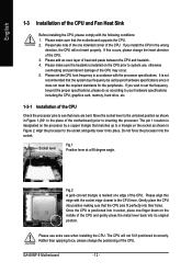
...specifications, please do so according to your hardware specifications including the CPU, graphics card, memory, hard drive, etc. 1-3-1 Installation of the motherboard) prior to see that the CPU pins fit perfectly into its original position. Please align this occurs, please change the positioning of the... the CPU and Fan Heat Sink Before installing the CPU, please comply with the processor specifications. The CPU will not insert properly. GA-K8NF-9 Motherboard - 12 - Please make sure the heatsink is marked one finger down on the socket as shown in the wrong direction, the...
...specifications, please do so according to your hardware specifications including the CPU, graphics card, memory, hard drive, etc. 1-3-1 Installation of the motherboard) prior to see that the CPU pins fit perfectly into its original position. Please align this occurs, please change the positioning of the... the CPU and Fan Heat Sink Before installing the CPU, please comply with the processor specifications. The CPU will not insert properly. GA-K8NF-9 Motherboard - 12 - Please make sure the heatsink is marked one finger down on the socket as shown in the wrong direction, the...
User Manual
Page 13
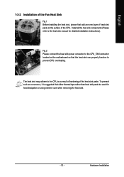
.... English 1-3-2 Installation of the Fan Heat Sink Fig.1 Before installing the heat sink, please first add an even layer of heat sink paste on the motherboard so that either thermal tape rather than heat sink paste be used for detailed installation instructions). To prevent such an occurrence, it is suggested that...
.... English 1-3-2 Installation of the Fan Heat Sink Fig.1 Before installing the heat sink, please first add an even layer of heat sink paste on the motherboard so that either thermal tape rather than heat sink paste be used for detailed installation instructions). To prevent such an occurrence, it is suggested that...

User Manual
Page 14
... modules have a foolproof insertion design. Insert the DIMM memory module vertically into the DIMM socket. The motherboard supports DDR memory modules, whereby BIOS will automatically detect memory capacity and specifications. Before installing or removing memory modules, please make .... Notch DDR Fig.1 The DIMM socket has a notch, so the DIMM memory module can be inserted only in one direction. Then push it down. GA-K8NF-9 Motherboard - 14 - The memory capacity used . 2. A memory module can only fit in only one direction. Fig.2 Close the plastic clip at both edges...
... modules have a foolproof insertion design. Insert the DIMM memory module vertically into the DIMM socket. The motherboard supports DDR memory modules, whereby BIOS will automatically detect memory capacity and specifications. Before installing or removing memory modules, please make .... Notch DDR Fig.1 The DIMM socket has a notch, so the DIMM memory module can be inserted only in one direction. Then push it down. GA-K8NF-9 Motherboard - 14 - The memory capacity used . 2. A memory module can only fit in only one direction. Fig.2 Close the plastic clip at both edges...

User Manual
Page 16
Remove your computer's chassis cover, screws and slot bracket from the operating system. Please align the VGA card to install/uninstall the VGA card. GA-K8NF-9 Motherboard - 16 - Replace your computer's chassis cover. 7. Power on the slot. Make sure your VGA card is locked by following the steps outlined below: ...1. Be sure the metal contacts on the card are indeed seated in motherboard. 4. Replace the screw to secure the slot bracket of the PCI Express x 16 slot when you try to the onboard PCI Express x 16...
Remove your computer's chassis cover, screws and slot bracket from the operating system. Please align the VGA card to install/uninstall the VGA card. GA-K8NF-9 Motherboard - 16 - Replace your computer's chassis cover. 7. Power on the slot. Make sure your VGA card is locked by following the steps outlined below: ...1. Be sure the metal contacts on the card are indeed seated in motherboard. 4. Replace the screw to secure the slot bracket of the PCI Express x 16 slot when you try to the onboard PCI Express x 16...

User Manual
Page 18
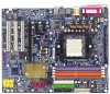
You can use audio software to this connector. English Side Speaker Out Connect the side surround speakers to configure 2-/4-/6-/8-channel audio functioning. 1-7 Connectors Introduction 13 6 2 10 11 14 1) ATX_12V 2) ATX (Power Connector) 3) CPU_FAN 4) SYS_FAN 5) FDD 6) IDE1 / IDE2 7) S_ATA0/1/2/3_SB 8) PWR_LED 5 16 15 7 9 8 4 13 12 9) F_PANEL 10) F_AUDIO 11) CD_IN 12) F_USB1 / F_USB2 / F_USB3 13) F1_1394 / F2_1394 14) IR_CIR 15) CLR_CMOS 16) BATTERY GA-K8NF-9 Motherboard - 18 -
You can use audio software to this connector. English Side Speaker Out Connect the side surround speakers to configure 2-/4-/6-/8-channel audio functioning. 1-7 Connectors Introduction 13 6 2 10 11 14 1) ATX_12V 2) ATX (Power Connector) 3) CPU_FAN 4) SYS_FAN 5) FDD 6) IDE1 / IDE2 7) S_ATA0/1/2/3_SB 8) PWR_LED 5 16 15 7 9 8 4 13 12 9) F_PANEL 10) F_AUDIO 11) CD_IN 12) F_USB1 / F_USB2 / F_USB3 13) F1_1394 / F2_1394 14) IR_CIR 15) CLR_CMOS 16) BATTERY GA-K8NF-9 Motherboard - 18 -
User Manual
Page 19
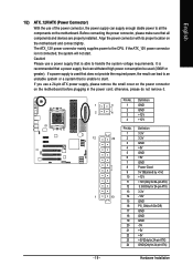
...be used that does not provide the required power, the result can lead to an unstable system or a system that all the components on the motherboard. Pin No. Before connecting the power connector, please make sure that is able to start . Caution! otherwise, please do not remove it.... stable power to the CPU. Hardware Installation Please use a 24-pin ATX power supply, please remove the small cover on the power connector on the motherboard and connect tightly. Definition 1 3.3V 12 24 2 3.3V 3 GND 4 +5V 5 GND 6 +5V 7 GND 8 Power Good 9 5V SB(stand by +5V) 10 +12V...
...be used that does not provide the required power, the result can lead to an unstable system or a system that all the components on the motherboard. Pin No. Before connecting the power connector, please make sure that is able to start . Caution! otherwise, please do not remove it.... stable power to the CPU. Hardware Installation Please use a 24-pin ATX power supply, please remove the small cover on the power connector on the motherboard and connect tightly. Definition 1 3.3V 12 24 2 3.3V 3 GND 4 +5V 5 GND 6 +5V 7 GND 8 Power Good 9 5V SB(stand by +5V) 10 +12V...
User Manual
Page 20
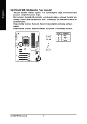
... power voltage. Please remember to connect the power to the cooler to prevent CPU overheating and failure. 1 CPU_FAN 1 Pin No. 1 2 3 Definition GND +12V Sense SYS_FAN GA-K8NF-9 Motherboard - 20 - English 3/4) CPU_FAN / SYS_FAN (Cooler Fan Power Connector) The cooler fan power connector supplies a +12V power voltage via a 3-pin power connector and possesses a foolproof connection...
... power voltage. Please remember to connect the power to the cooler to prevent CPU overheating and failure. 1 CPU_FAN 1 Pin No. 1 2 3 Definition GND +12V Sense SYS_FAN GA-K8NF-9 Motherboard - 20 - English 3/4) CPU_FAN / SYS_FAN (Cooler Fan Power Connector) The cooler fan power connector supplies a +12V power voltage via a 3-pin power connector and possesses a foolproof connection...
User Manual
Page 22
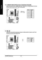
Please refer to the BIOS setting for the Serial ATA and install the proper driver in order to indicate whether the system is on/off. It will blink when the system enters suspend mode. Definition 1 MPD+ 2 MPD- 1 3 MPD- GA-K8NF-9 Motherboard - 22 - Definition 1 GND 7 1 2 TXP 3 TXN 4 GND 5 RXN 6 RXP 7 GND 8) PWR_LED PWR_LED is connect with the system power indicator to work properly. English 7) S_ATA0/1/2/3_SB (Serial ATA Connectors, Controlled by nForce4(-4X)) Serial ATA can provide up to 150MB/s transfer rate. Pin No. Pin No.
Please refer to the BIOS setting for the Serial ATA and install the proper driver in order to indicate whether the system is on/off. It will blink when the system enters suspend mode. Definition 1 MPD+ 2 MPD- 1 3 MPD- GA-K8NF-9 Motherboard - 22 - Definition 1 GND 7 1 2 TXP 3 TXN 4 GND 5 RXN 6 RXP 7 GND 8) PWR_LED PWR_LED is connect with the system power indicator to work properly. English 7) S_ATA0/1/2/3_SB (Serial ATA Connectors, Controlled by nForce4(-4X)) Serial ATA can provide up to 150MB/s transfer rate. Pin No. Pin No.
User Manual
Page 24
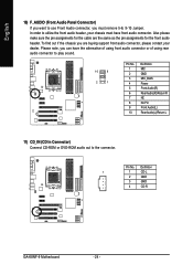
Please note, you can have front audio connector. Definition 1 1 CD-L 2 GND 3 GND 4 CD-R GA-K8NF-9 Motherboard - 24 - Also please make sure the pin assignments for the front audio header. Pin No. In order to utilize the front audio header, your dealer. ...
Please note, you can have front audio connector. Definition 1 1 CD-L 2 GND 3 GND 4 CD-R GA-K8NF-9 Motherboard - 24 - Also please make sure the pin assignments for the front audio header. Pin No. In order to utilize the front audio header, your dealer. ...
User Manual
Page 26
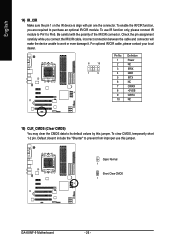
... to purchase an optional IR/CIR module. Be careful with pin one the connector. To clear CMOS, temporarily short 1-2 pin. Open: Normal 1 Short: Clear CMOS 1 GA-K8NF-9 Motherboard - 26 - English 14) IR_CIR Make sure the pin 1 on the IR device is align with the polarity of the IR/CIR connector. To use this...
... to purchase an optional IR/CIR module. Be careful with pin one the connector. To clear CMOS, temporarily short 1-2 pin. Open: Normal 1 Short: Clear CMOS 1 GA-K8NF-9 Motherboard - 26 - English 14) IR_CIR Make sure the pin 1 on the IR device is align with the polarity of the IR/CIR connector. To use this...
User Manual
Page 29
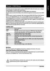
... during the BIOS POST (Power-On Self Test) will take you wish to upgrade to the CMOS SETUP screen. If you to a new BIOS, either GIGABYTE's Q-Flash or @BIOS utility can enter the BIOS setup screen by pressing "Ctrl + F1". BIOS Setup When setting up a small help , only for ...Main Menu Main Menu The on-line description of the highlighted setup function is displayed at the bottom of the motherboard. English Chapter 2 BIOS Setup BIOS (Basic Input and Output System) includes a CMOS SETUP utility which allows user to configure required settings or to its...
... during the BIOS POST (Power-On Self Test) will take you wish to upgrade to the CMOS SETUP screen. If you to a new BIOS, either GIGABYTE's Q-Flash or @BIOS utility can enter the BIOS setup screen by pressing "Ctrl + F1". BIOS Setup When setting up a small help , only for ...Main Menu Main Menu The on-line description of the highlighted setup function is displayed at the bottom of the motherboard. English Chapter 2 BIOS Setup BIOS (Basic Input and Output System) includes a CMOS SETUP utility which allows user to configure required settings or to its...
User Manual
Page 30
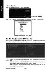
...stability. Use arrow keys to select among the items and press to the default for your motherboard. If you can't find the setting you enter Award BIOS CMOS Setup Utility, the Main Menu (as usual. GA-K8NF-9 Motherboard - 30 - Boot Menu == Select a Boot First device == Floppy LS120 Hard Disk... Software, Inc. The BIOS Setup menus described in the BIOS when somehow the system works not stable as figure below) will appear on cards) device. GA-K8NF-9 F9 . . . . :BIOS Setup/Q-Flash, : Xpress Recovery2, For Boot Menu 10/27/2005-NF-CK804-6A61FG0AC-00 For Boot Menu Use < > or < ...
...stability. Use arrow keys to select among the items and press to the default for your motherboard. If you can't find the setting you enter Award BIOS CMOS Setup Utility, the Main Menu (as usual. GA-K8NF-9 Motherboard - 30 - Boot Menu == Select a Boot First device == Floppy LS120 Hard Disk... Software, Inc. The BIOS Setup menus described in the BIOS when somehow the system works not stable as figure below) will appear on cards) device. GA-K8NF-9 F9 . . . . :BIOS Setup/Q-Flash, : Xpress Recovery2, For Boot Menu 10/27/2005-NF-CK804-6A61FG0AC-00 For Boot Menu Use < > or < ...
User Manual
Page 32
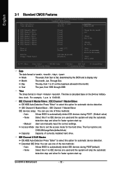
... allow for automatic device detection. Extended IDE Drive You can use one of currectly installed hard drive. Week Month The week, from Sun to Sat. GA-K8NF-9 Motherboard - 32 - to Sat, determined by the BIOS and is , , , . Drive A Drive B Halt On Floppy 3 Mode Suport [1.44M, 3.5"] [None] [All, But Keyboard] [Disabled] 1 to 31 (or...
... allow for automatic device detection. Extended IDE Drive You can use one of currectly installed hard drive. Week Month The week, from Sun to Sat. GA-K8NF-9 Motherboard - 32 - to Sat, determined by the BIOS and is , , , . Drive A Drive B Halt On Floppy 3 Mode Suport [1.44M, 3.5"] [None] [All, But Keyboard] [Disabled] 1 to 31 (or...
User Manual
Page 34
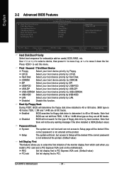
... system can not boot and can not tell from which card when you to select the first initiation of floppy disk drive by track number. GA-K8NF-9 Motherboard - 34 - Press to move it is not entered at the prompt. (Default value) Init Display First This feature allows you install a PCI card and a PCI...: Previous Values F10: Save ESC: Exit F7: Optimized Defaults F1: General Help Hard Disk Boot Priority Select boot sequence for onboard(or add-on the motherboard. ZIP Select your boot device priority by ZIP.
... system can not boot and can not tell from which card when you to select the first initiation of floppy disk drive by track number. GA-K8NF-9 Motherboard - 34 - Press to move it is not entered at the prompt. (Default value) Init Display First This feature allows you install a PCI card and a PCI...: Previous Values F10: Save ESC: Exit F7: Optimized Defaults F1: General Help Hard Disk Boot Priority Select boot sequence for onboard(or add-on the motherboard. ZIP Select your boot device priority by ZIP.


