Manual
Page 1
GA-GC220 Socket 479 motherboard for Intel® Celeron® 220 processor User's Manual Rev. 1001 12ME-GC220-1001R
GA-GC220 Socket 479 motherboard for Intel® Celeron® 220 processor User's Manual Rev. 1001 12ME-GC220-1001R

Manual
Page 2
Motherboard GA-GC220 Apr. 1, 2008 Motherboard GA-GC220 Apr. 1, 2008
Motherboard GA-GC220 Apr. 1, 2008 Motherboard GA-GC220 Apr. 1, 2008
Manual
Page 3
... technical information. is 1.0. Example: For product-related information, check on our website at: http://www.gigabyte.com.tw Identifying Your Motherboard Revision The revision number on how to GIGABYTE UNITED INC. For example, "REV: 1.0" means the revision of GIGABYTE branded motherboards. Copyright © 2008 GIGA-BYTE TECHNOLOGY CO., LTD. All rights reserved. Documentation Classifications In...
... technical information. is 1.0. Example: For product-related information, check on our website at: http://www.gigabyte.com.tw Identifying Your Motherboard Revision The revision number on how to GIGABYTE UNITED INC. For example, "REV: 1.0" means the revision of GIGABYTE branded motherboards. Copyright © 2008 GIGA-BYTE TECHNOLOGY CO., LTD. All rights reserved. Documentation Classifications In...
Manual
Page 4
Table of Contents Box Contents ...6 OptionalItems ...6 GA-GC220 Motherboard Layout 7 Block Diagram ...8 Chapter 1 Hardware Installation 9 1-1 Installation Precautions 9 1-2 Product Specifications 10 1-3 Installing the Memory 12 1-4 Back Panel Connectors 13 1-5 Internal Connectors 15 Chapter 2 BIOS Setup ...
Table of Contents Box Contents ...6 OptionalItems ...6 GA-GC220 Motherboard Layout 7 Block Diagram ...8 Chapter 1 Hardware Installation 9 1-1 Installation Precautions 9 1-2 Product Specifications 10 1-3 Installing the Memory 12 1-4 Back Panel Connectors 13 1-5 Internal Connectors 15 Chapter 2 BIOS Setup ...

Manual
Page 6
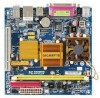
Optional Items 2-port USB 2.0 bracket (Part No. 12CR1-1UB030-51R) 2-port SATA power cable (Part No. 12CF1-2SERPW-01R) - 6 - The box contents are for reference only. Box Contents GA-GC220 motherboard Motherboard driver disk User's Manual One IDE cable One SATA 3Gb/s cables I/O Shield • The box contents above are subject to change without notice. • The motherboard image is for reference only and the actual items shall depend on product package you obtain.
Optional Items 2-port USB 2.0 bracket (Part No. 12CR1-1UB030-51R) 2-port SATA power cable (Part No. 12CF1-2SERPW-01R) - 6 - The box contents are for reference only. Box Contents GA-GC220 motherboard Motherboard driver disk User's Manual One IDE cable One SATA 3Gb/s cables I/O Shield • The box contents above are subject to change without notice. • The motherboard image is for reference only and the actual items shall depend on product package you obtain.
Manual
Page 9
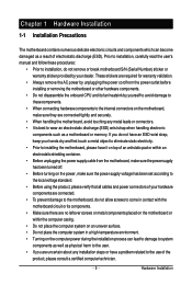
... connecting hardware components to the internal connectors on the power, make sure they are connected tightly and securely. • When handling the motherboard, avoid touching any installation steps or have a problem related to installation, do not have an ESD wrist strap, keep your dealer. ...or within an electrostatic shielding container. • Before unplugging the power supply cable from the power outlet before installing or removing the motherboard or other hardware components. • Do not disassemble the onboard CPU and its components. • Make sure there are uncertain ...
... connecting hardware components to the internal connectors on the power, make sure they are connected tightly and securely. • When handling the motherboard, avoid touching any installation steps or have a problem related to installation, do not have an ESD wrist strap, keep your dealer. ...or within an electrostatic shielding container. • Before unplugging the power supply cable from the power outlet before installing or removing the motherboard or other hardware components. • Do not disassemble the onboard CPU and its components. • Make sure there are uncertain ...
Manual
Page 10
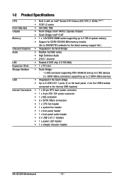
...; ICH7 Memory Š 1 x 1.8V DDR2 DIMM socket supporting up to 2 GB of system memory Š Support for DDR2 533/400 MHz memory module (Go to GIGABYTE's website for the latest memory support list.) Onboard Graphics Š Integrated in the North Bridge Audio Š Realtek ALC662 codec Š High Definition Audio Š... header Š 1 x system fan header Š 1 x front panel header Š 1 x front panel audio header Š 2 x USB 2.0/1.1 headers Š 1 x power LED header Š 1 x chassis intrusion header GA-GC220 Motherboard - 10 -
...; ICH7 Memory Š 1 x 1.8V DDR2 DIMM socket supporting up to 2 GB of system memory Š Support for DDR2 533/400 MHz memory module (Go to GIGABYTE's website for the latest memory support list.) Onboard Graphics Š Integrated in the North Bridge Audio Š Realtek ALC662 codec Š High Definition Audio Š... header Š 1 x system fan header Š 1 x front panel header Š 1 x front panel audio header Š 2 x USB 2.0/1.1 headers Š 1 x power LED header Š 1 x chassis intrusion header GA-GC220 Motherboard - 10 -

Manual
Page 11
... not disassemble the onboard CPU and its fan heatsink by yourself to avoid damage to these components. (Note 2) Available functions in EasyTune may differ by motherboard model. - 11 -
... not disassemble the onboard CPU and its fan heatsink by yourself to avoid damage to these components. (Note 2) Available functions in EasyTune may differ by motherboard model. - 11 -
Manual
Page 12
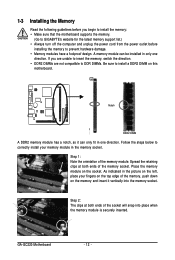
...can be installed in the memory socket. If you begin to install the memory: • Make sure that the motherboard supports the memory. (Go to GIGABYTE's website for the latest memory support list.) • Always turn off the computer and unplug the power cord from...into place when the memory module is securely inserted. Spread the retaining clips at both ends of the socket will snap into the memory socket. GA-GC220 Motherboard - 12 - 1-3 Installing the Memory Read the following guidelines before installing the memory to prevent hardware damage. • Memory modules have a...
...can be installed in the memory socket. If you begin to install the memory: • Make sure that the motherboard supports the memory. (Go to GIGABYTE's website for the latest memory support list.) • Always turn off the computer and unplug the power cord from...into place when the memory module is securely inserted. Spread the retaining clips at both ends of the socket will snap into the memory socket. GA-GC220 Motherboard - 12 - 1-3 Installing the Memory Read the following guidelines before installing the memory to prevent hardware damage. • Memory modules have a...
Manual
Page 13
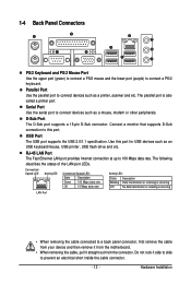
... is also called a printer port. USB Port The USB port supports the USB 2.0/1.1 specification. Use this port. Do not rock it straight out from the motherboard. • When removing the cable, pull it side to side to connect a PS/2 keyboard. Parallel Port Use the parallel port to connect devices such as...
... is also called a printer port. USB Port The USB port supports the USB 2.0/1.1 specification. Use this port. Do not rock it straight out from the motherboard. • When removing the cable, pull it side to side to connect a PS/2 keyboard. Parallel Port Use the parallel port to connect devices such as...

Manual
Page 14
Line In Jack (Blue) The default line in devices such as an optical drive, walkman, etc. GA-GC220 Motherboard - 14 - This jack can be connected to this jack. Use this audio jack for a headphone or 2-channel speaker. Use this audio jack for line in jack. Microphones must be used to the instructions on setting up a 2/4/5.1-channel audio configuration in jack. Refer to connect front speakers in a 4/5.1-channel audio configuration. Line Out Jack (Green) The default line out jack. Mic In Jack (Pink) The default Mic in Chapter 5, "Configuring 2/4/5.1-Channel Audio."
Line In Jack (Blue) The default line in devices such as an optical drive, walkman, etc. GA-GC220 Motherboard - 14 - This jack can be connected to this jack. Use this audio jack for a headphone or 2-channel speaker. Use this audio jack for line in jack. Microphones must be used to the instructions on setting up a 2/4/5.1-channel audio configuration in jack. Refer to connect front speakers in a 4/5.1-channel audio configuration. Line Out Jack (Green) The default line out jack. Mic In Jack (Pink) The default Mic in Chapter 5, "Configuring 2/4/5.1-Channel Audio."
Manual
Page 15
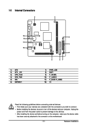
... 2) ATX _12V 3) CPU_FAN 4) SYS_FAN 5) IDE 6) SATAII0/1 4 1 9 6 57 7) PWR_LED 8) BAT1 9) F_PANEL 10) F_AUDIO 11) F_USB1/F_USB2 12) CI Read the following guidelines before turning on the motherboard. - 15 -
... 2) ATX _12V 3) CPU_FAN 4) SYS_FAN 5) IDE 6) SATAII0/1 4 1 9 6 57 7) PWR_LED 8) BAT1 9) F_PANEL 10) F_AUDIO 11) F_USB1/F_USB2 12) CI Read the following guidelines before turning on the motherboard. - 15 -

Manual
Page 16
The power connector possesses a foolproof design. If the 12V power connector is turned off and all the components on the motherboard. Connect the power supply cable to the CPU. Before connecting the power connector, first make sure the power supply is not connected, the computer will ... No. 11 12 13 14 15 16 17 18 19 20 Definition 3.3V -12V GND PS_ON(soft On/Off) GND GND GND -5V +5V +5V GA-GC220 Motherboard - 16 - The 12V power connector mainly supplies power to the power connector in the correct orientation. 1/2) ATX_12V/ATX (2x2 12V Power Connector and 2x12 Main...
The power connector possesses a foolproof design. If the 12V power connector is turned off and all the components on the motherboard. Connect the power supply cable to the CPU. Before connecting the power connector, first make sure the power supply is not connected, the computer will ... No. 11 12 13 14 15 16 17 18 19 20 Definition 3.3V -12V GND PS_ON(soft On/Off) GND GND GND -5V +5V +5V GA-GC220 Motherboard - 16 - The 12V power connector mainly supplies power to the power connector in the correct orientation. 1/2) ATX_12V/ATX (2x2 12V Power Connector and 2x12 Main...
Manual
Page 17
... wire indicates a positive connection and requires a +12V voltage. Before attaching the IDE cable, locate the foolproof groove on the connector. 3/4) CPU_FAN/SYS_FAN (Fan Headers) The motherboard has a 3-pin CPU fan header (CPU_FAN) and a 3-pin system fan header (SYS_FAN). If you wish to connect two IDE devices, remember to set the jumpers...
... wire indicates a positive connection and requires a +12V voltage. Before attaching the IDE cable, locate the foolproof groove on the connector. 3/4) CPU_FAN/SYS_FAN (Fan Headers) The motherboard has a 3-pin CPU fan header (CPU_FAN) and a 3-pin system fan header (SYS_FAN). If you wish to connect two IDE devices, remember to set the jumpers...
Manual
Page 18
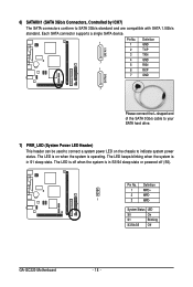
... on the chassis to SATA 3Gb/s standard and are compatible with SATA 1.5Gb/s standard. System Status LED S0 On S1 Blinking S3/S4/S5 Off GA-GC220 Motherboard - 18 - Pin No. The LED is off when the system is operating. Pin No. Definition 1 MPD+ 2 MPD- 1 3 MPD- Each SATA connector supports a single SATA device...
... on the chassis to SATA 3Gb/s standard and are compatible with SATA 1.5Gb/s standard. System Status LED S0 On S1 Blinking S3/S4/S5 Off GA-GC220 Motherboard - 18 - Pin No. The LED is off when the system is operating. Pin No. Definition 1 MPD+ 2 MPD- 1 3 MPD- Each SATA connector supports a single SATA device...
Manual
Page 20
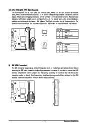
GA-GC220 Motherboard - 20 - HDHD+ Reset Switch Hard Drive Activity LED • MSG (Message/Power/Sleep LED): System Status LED Connects to the power switch on the chassis ...
GA-GC220 Motherboard - 20 - HDHD+ Reset Switch Hard Drive Activity LED • MSG (Message/Power/Sleep LED): System Status LED Connects to the power switch on the chassis ...

Manual
Page 21
...the wire assignments of the module connector match the pin assignments of a single plug. Incorrect connection between the module connector and the motherboard header will make the device unable to activate AC'97 functioninality via the audio software in Chapter 5, "Configuring 2/4/5.1-Channel Audio." &#...module to this header. For information about connecting the front panel audio module that has separated connectors on each wire instead of the motherboard header. 10) F_AUDIO (Front Panel Audio Header) The front panel audio header supports Intel High Definition audio (HD) and AC'97...
...the wire assignments of the module connector match the pin assignments of a single plug. Incorrect connection between the module connector and the motherboard header will make the device unable to activate AC'97 functioninality via the audio software in Chapter 5, "Configuring 2/4/5.1-Channel Audio." &#...module to this header. For information about connecting the front panel audio module that has separated connectors on each wire instead of the motherboard header. 10) F_AUDIO (Front Panel Audio Header) The front panel audio header supports Intel High Definition audio (HD) and AC'97...

Manual
Page 22
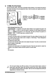
11) F_USB1/F_USB2 (USB Headers) The headers conform to the USB bracket. 12) CI (Chassis Intrusion Header) This motherboard provides a chassis detection feature that detects if the chassis cover has been removed. For purchasing the optional USB bracket, please contact the local dealer. 10 9 2 1 ... outlet to prevent damage to USB 2.0/1.1 specification. Each USB header can provide two USB ports via an optional USB bracket. Pin No. Definition 1 Signal 1 2 GND GA-GC220 Motherboard - 22 - This function requires a chassis with chassis intrusion detection design.
11) F_USB1/F_USB2 (USB Headers) The headers conform to the USB bracket. 12) CI (Chassis Intrusion Header) This motherboard provides a chassis detection feature that detects if the chassis cover has been removed. For purchasing the optional USB bracket, please contact the local dealer. 10 9 2 1 ... outlet to prevent damage to USB 2.0/1.1 specification. Each USB header can provide two USB ports via an optional USB bracket. Pin No. Definition 1 Signal 1 2 GND GA-GC220 Motherboard - 22 - This function requires a chassis with chassis intrusion detection design.

Manual
Page 23
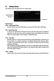
...the BIOS Setup program, press the key during system startup, saving system parameters and loading operating system, etc. For instructions on the motherboard supplies the necessary power to the CMOS to Chapter 4, "BIOS Update Utilities." • Because BIOS flashing is recommended that you not... or other unexpected results. Inadequately altering the settings may result in the CMOS on . BIOS Setup To upgrade the BIOS, use either the GIGABYTE Q-Flash or @BIOS utility. • Q-Flash allows the user to boot. Refer to Chapter 5, "Troubleshooting," for how to activate certain...
...the BIOS Setup program, press the key during system startup, saving system parameters and loading operating system, etc. For instructions on the motherboard supplies the necessary power to the CMOS to Chapter 4, "BIOS Update Utilities." • Because BIOS flashing is recommended that you not... or other unexpected results. Inadequately altering the settings may result in the CMOS on . BIOS Setup To upgrade the BIOS, use either the GIGABYTE Q-Flash or @BIOS utility. • Q-Flash allows the user to boot. Refer to Chapter 5, "Troubleshooting," for how to activate certain...
Manual
Page 24
...If you to enter BIOS Setup first. To exit Boot Menu, press . Note: The setting in Boot Menu. Motherboard Model BIOS Version Award Modular BIOS v6.00PG, An Energy Star Ally Copyright (C) 1984-2008, Award Software, Inc. ...is effective for subsequent access to accept. In Boot Menu, use the up hard drive data using the motherboard driver disk, the key can access Boot Menu again to change the first boot device setting as needed...to select the first boot device, then press to XpressRecovery2 during the POST. GA-GC220 Motherboard - 24 - The system will still be used for one time only.
...If you to enter BIOS Setup first. To exit Boot Menu, press . Note: The setting in Boot Menu. Motherboard Model BIOS Version Award Modular BIOS v6.00PG, An Energy Star Ally Copyright (C) 1984-2008, Award Software, Inc. ...is effective for subsequent access to accept. In Boot Menu, use the up hard drive data using the motherboard driver disk, the key can access Boot Menu again to change the first boot device setting as needed...to select the first boot device, then press to XpressRecovery2 during the POST. GA-GC220 Motherboard - 24 - The system will still be used for one time only.


