Manual
Page 4
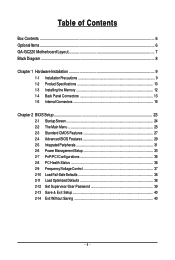
...Motherboard Layout 7 Block Diagram ...8 Chapter 1 Hardware Installation 9 1-1 Installation Precautions 9 1-2 Product Specifications 10 1-3 Installing the Memory 12 1-4 Back Panel Connectors 13 1-5 Internal Connectors 15 Chapter 2 BIOS Setup 23 2-1 Startup Screen 24 2-2 The Main Menu 25 2-3 Standard CMOS Features 27 2-4 Advanced BIOS Features 29 2-5 IntegratedPeripherals 31 2-6 Power Management Setup 33 2-7 PnP/PCI Configurations 35 2-8 PC Health Status 36 2-9 Frequency/Voltage Control 37 2-10 Load Fail-Safe Defaults 38 2-11 Load Optimized Defaults 38 2-12 Set Supervisor/User...
...Motherboard Layout 7 Block Diagram ...8 Chapter 1 Hardware Installation 9 1-1 Installation Precautions 9 1-2 Product Specifications 10 1-3 Installing the Memory 12 1-4 Back Panel Connectors 13 1-5 Internal Connectors 15 Chapter 2 BIOS Setup 23 2-1 Startup Screen 24 2-2 The Main Menu 25 2-3 Standard CMOS Features 27 2-4 Advanced BIOS Features 29 2-5 IntegratedPeripherals 31 2-6 Power Management Setup 33 2-7 PnP/PCI Configurations 35 2-8 PC Health Status 36 2-9 Frequency/Voltage Control 37 2-10 Load Fail-Safe Defaults 38 2-11 Load Optimized Defaults 38 2-12 Set Supervisor/User...
Manual
Page 10
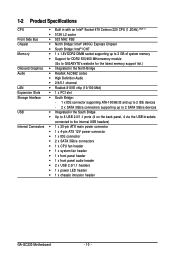
...2 SATA 3Gb/s devices USB Š Integrated in the South Bridge Š Up to 8 USB 2.0/1.1 ports (4 on the back panel, 4 via the USB brackets connected to the internal USB headers) Internal Connectors Š 1 x 20-pin ATX main power connector Š 1 x 4-pin ATX 12V power connector Š 1 x IDE connector Š 2 x SATA 3Gb/s connectors Š 1 x CPU fan header Š 1 x system fan header Š 1 x front panel header Š 1 x front panel audio header Š 2 x USB 2.0/1.1 headers Š 1 x power LED header Š 1 x chassis intrusion header GA-GC220 Motherboard - 10...
...2 SATA 3Gb/s devices USB Š Integrated in the South Bridge Š Up to 8 USB 2.0/1.1 ports (4 on the back panel, 4 via the USB brackets connected to the internal USB headers) Internal Connectors Š 1 x 20-pin ATX main power connector Š 1 x 4-pin ATX 12V power connector Š 1 x IDE connector Š 2 x SATA 3Gb/s connectors Š 1 x CPU fan header Š 1 x system fan header Š 1 x front panel header Š 1 x front panel audio header Š 2 x USB 2.0/1.1 headers Š 1 x power LED header Š 1 x chassis intrusion header GA-GC220 Motherboard - 10...

Manual
Page 11
Back Panel Connectors I/O Controller Hardware Monitor BIOS Unique Features Bundled Software Operating System Form Factor Š 1 x PS/2 keyboard port Š 1 x PS/2 mouse port Š 1 x parallel port Š 1 x serial port Š 1 x D-Sub port Š 4 x USB 2.0/1.1 ports Š 1 x RJ-45 port Š 3 x audio jacks (Line In/Line Out/Microphone) Š iTE IT8718 chip Š System voltage detection Š CPU temperature detection Š CPU/System fan speed detection Š CPU fan speed control Š 1 x 4 Mbit flash Š Use of licensed AWARD BIOS Š PnP 1.0a, DMI...
Back Panel Connectors I/O Controller Hardware Monitor BIOS Unique Features Bundled Software Operating System Form Factor Š 1 x PS/2 keyboard port Š 1 x PS/2 mouse port Š 1 x parallel port Š 1 x serial port Š 1 x D-Sub port Š 4 x USB 2.0/1.1 ports Š 1 x RJ-45 port Š 3 x audio jacks (Line In/Line Out/Microphone) Š iTE IT8718 chip Š System voltage detection Š CPU temperature detection Š CPU/System fan speed detection Š CPU fan speed control Š 1 x 4 Mbit flash Š Use of licensed AWARD BIOS Š PnP 1.0a, DMI...
Manual
Page 17
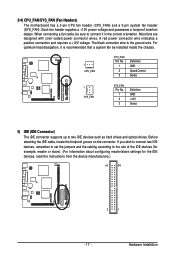
... two IDE devices such as hard drives and optical drives. When connecting a fan cable, be sure to connect it is the ground wire. For optimum heat dissipation, it in the correct orientation. Hardware Installation Each fan header supplies a +12V power voltage and possesses a foolproof insertion design. Most fans are designed with color-coded power connector wires. Before attaching the IDE cable, locate the foolproof groove on the connector. 3/4) CPU_FAN/SYS_FAN (Fan Headers) The motherboard has a 3-pin CPU fan header (CPU_FAN) and a 3-pin system fan header...
... two IDE devices such as hard drives and optical drives. When connecting a fan cable, be sure to connect it is the ground wire. For optimum heat dissipation, it in the correct orientation. Hardware Installation Each fan header supplies a +12V power voltage and possesses a foolproof insertion design. Most fans are designed with color-coded power connector wires. Before attaching the IDE cable, locate the foolproof groove on the connector. 3/4) CPU_FAN/SYS_FAN (Fan Headers) The motherboard has a 3-pin CPU fan header (CPU_FAN) and a 3-pin system fan header...

Manual
Page 21
... this header. Hardware Installation Make sure the wire assignments of the module connector match the pin assignments of a single plug. Incorrect connection between the module connector and the motherboard header will make the device unable to the instructions on each wire instead of the motherboard header. For HD Front Panel Audio: For AC'97 Front Panel Audio: 1 2 Pin No. Definition 1 MIC2_L Pin No. 1 Definition MIC 2 9 10 3 GND MIC2_R 2 GND 3 MIC Power 4 -ACZ_DET...
... this header. Hardware Installation Make sure the wire assignments of the module connector match the pin assignments of a single plug. Incorrect connection between the module connector and the motherboard header will make the device unable to the instructions on each wire instead of the motherboard header. For HD Front Panel Audio: For AC'97 Front Panel Audio: 1 2 Pin No. Definition 1 MIC2_L Pin No. 1 Definition MIC 2 9 10 3 GND MIC2_R 2 GND 3 MIC Power 4 -ACZ_DET...

Manual
Page 23
... searches and downloads the latest version of the battery/clearing CMOS jumper in system's failure to prevent system instability or other unexpected results. If this occurs, try to clear the CMOS values and reset the board to default values. (Refer to activate certain system features. To upgrade the BIOS, use either the GIGABYTE Q-Flash or @BIOS utility. • Q-Flash allows the user to quickly and easily upgrade or back up BIOS without entering the...
... searches and downloads the latest version of the battery/clearing CMOS jumper in system's failure to prevent system instability or other unexpected results. If this occurs, try to clear the CMOS values and reset the board to default values. (Refer to activate certain system features. To upgrade the BIOS, use either the GIGABYTE Q-Flash or @BIOS utility. • Q-Flash allows the user to quickly and easily upgrade or back up BIOS without entering the...
Manual
Page 26
.../CPU temperature, system voltage and fan speed, etc. „ Frequency/Voltage Control Use this menu to the confirmation message will exit BIOS Setup. (Pressing can also carry out this task.) GA-GC220 Motherboard - 26 - „ Standard CMOS Features Use this menu to configure the system time and date, hard drive types, and the type of your CPU, memory, etc. „ Load Fail-Safe Defaults Fail-Safe defaults are factory settings for the most stable, minimal-performance system operations. „ Load Optimized Defaults Optimized defaults...
.../CPU temperature, system voltage and fan speed, etc. „ Frequency/Voltage Control Use this menu to the confirmation message will exit BIOS Setup. (Pressing can also carry out this task.) GA-GC220 Motherboard - 26 - „ Standard CMOS Features Use this menu to configure the system time and date, hard drive types, and the type of your CPU, memory, etc. „ Load Fail-Safe Defaults Fail-Safe defaults are factory settings for the most stable, minimal-performance system operations. „ Load Optimized Defaults Optimized defaults...
Manual
Page 27
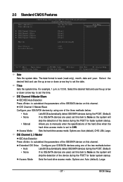
... key to set to manually enter the specifications of the IDE/SATA device on this channel. Options are : Auto (default), CHS, LBA, Large. Select the desired field and use the up arrow or down arrow key to set the date. For example, 1 p.m. Access Mode Sets the hard drive access mode. The date format is 13:0:0. IDE Channel 0 Master/Slave IDE HDD Auto-Detection Press to autodetect the parameters of the hard drive when the hard drive access mode is set the time. BIOS Setup Access Mode Sets the hard drive access mode. Time Sets...
... key to set to manually enter the specifications of the IDE/SATA device on this channel. Options are : Auto (default), CHS, LBA, Large. Select the desired field and use the up arrow or down arrow key to set the date. For example, 1 p.m. Access Mode Sets the hard drive access mode. The date format is 13:0:0. IDE Channel 0 Master/Slave IDE HDD Auto-Detection Press to autodetect the parameters of the hard drive when the hard drive access mode is set the time. BIOS Setup Access Mode Sets the hard drive access mode. Time Sets...
Manual
Page 29
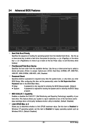
... hardware monitor utility is required for booting the system and for Windows XP operating system; After configuring this item to 3 Allows you enter BIOS Setup. to Enabled for legacy operating system such as Windows NT4.0. (Default: Disabled) - 29 - Use the up or down arrow key to select a hard drive, then press the plus key (or ) or the minus key (or ) to 3 No-Execute Memory Protect [Disabled] [Disabled] [Enabled] CPU Thermal Monitor 2(TM2) [Enabled] Init Display First [PCI] On-Chip...
... hardware monitor utility is required for booting the system and for Windows XP operating system; After configuring this item to 3 Allows you enter BIOS Setup. to Enabled for legacy operating system such as Windows NT4.0. (Default: Disabled) - 29 - Use the up or down arrow key to select a hard drive, then press the plus key (or ) or the minus key (or ) to 3 No-Execute Memory Protect [Disabled] [Disabled] [Enabled] CPU Thermal Monitor 2(TM2) [Enabled] Init Display First [PCI] On-Chip...
Manual
Page 30
... the monitor display from the installed PCI graphics card or the onboard VGA. PCI Sets the PCI graphics card as the first display. (Default) Onboard Sets the onboard VGA as the first display. When enabled, the CPU core frequency and voltage will use only this memory for the computer, reducing exposure to viruses and malicious buffer overflow attacks when working with its supporting software and system. (Default: Enabled) CPU Thermal Monitor 2 (TM2) Enables or disables Intel® CPU Thermal Monitor (TM2) function, a CPU overheating protection function. GA-GC220 Motherboard - 30...
... the monitor display from the installed PCI graphics card or the onboard VGA. PCI Sets the PCI graphics card as the first display. (Default) Onboard Sets the onboard VGA as the first display. When enabled, the CPU core frequency and voltage will use only this memory for the computer, reducing exposure to viruses and malicious buffer overflow attacks when working with its supporting software and system. (Default: Enabled) CPU Thermal Monitor 2 (TM2) Enables or disables Intel® CPU Thermal Monitor (TM2) function, a CPU overheating protection function. GA-GC220 Motherboard - 30...
Manual
Page 31
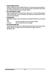
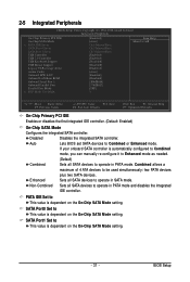
...BIOS Setup 2-5 Integrated Peripherals CMOS Setup Utility-Copyright (C) 1984-2008 Award Software Integrated Peripherals On-Chip Primary PCI IDE On-Chip SATA Mode x PATA IDE Set to SATA Port 0 Set to SATA Port 1 Set to be used simultaneously: two PATA devices plus two SATA devices. Enhanced Sets all SATA devices to operate in PATA mode and disables the integrated IDE controller. Combined allows a maximum of 4 ATA devices to USB Controller USB 2.0 Controller USB Keyboard Support USB Mouse Support Legacy USB storage detect Azalia Codec Onboard H/W LAN Onboard LAN Boot ROM Onboard...
...BIOS Setup 2-5 Integrated Peripherals CMOS Setup Utility-Copyright (C) 1984-2008 Award Software Integrated Peripherals On-Chip Primary PCI IDE On-Chip SATA Mode x PATA IDE Set to SATA Port 0 Set to SATA Port 1 Set to be used simultaneously: two PATA devices plus two SATA devices. Enhanced Sets all SATA devices to operate in PATA mode and disables the integrated IDE controller. Combined allows a maximum of 4 ATA devices to USB Controller USB 2.0 Controller USB Keyboard Support USB Mouse Support Legacy USB storage detect Azalia Codec Onboard H/W LAN Onboard LAN Boot ROM Onboard...
Manual
Page 32
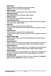
...USB 2.0 controller. (Default: Enabled) USB Keyboard Support Allows USB keyboard to be used in MS-DOS. (Default: Disabled) USB Mouse Support Allows USB mouse to be used in MS-DOS. (Default: Disabled) Legacy USB storage detect Determines whether to detect USB storage devices, including USB flash drives and USB hard drives during the POST. (Default: Enabled) Azalia Codec Enables or disables the onboard audio function. (Default: Auto) If you wish to install a 3rd party add-in network card instead of using the onboard audio, set to ECP or ECP+EPP mode. Options are : 3 (default), 1. Options...
...USB 2.0 controller. (Default: Enabled) USB Keyboard Support Allows USB keyboard to be used in MS-DOS. (Default: Disabled) USB Mouse Support Allows USB mouse to be used in MS-DOS. (Default: Disabled) Legacy USB storage detect Determines whether to detect USB storage devices, including USB flash drives and USB hard drives during the POST. (Default: Enabled) Azalia Codec Enables or disables the onboard audio function. (Default: Auto) If you wish to install a 3rd party add-in network card instead of using the onboard audio, set to ECP or ECP+EPP mode. Options are : 3 (default), 1. Options...
Manual
Page 33
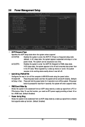
... F7: Optimized Defaults ACPI Suspend Type Specifies the ACPI sleep state when the system enters suspend. Press and hold the power button for less than in the S1 state. 2-6 Power Management Setup CMOS Setup Utility-Copyright (C) 1984-2008 Award Software Power Management Setup ACPI Suspend Type Soft-Off by PWR-BTTN PME Event Wake Up Power On by Ring Resume by a wake-up device or event, the system resumes to its working state exactly...
... F7: Optimized Defaults ACPI Suspend Type Specifies the ACPI sleep state when the system enters suspend. Press and hold the power button for less than in the S1 state. 2-6 Power Management Setup CMOS Setup Utility-Copyright (C) 1984-2008 Award Software Power Management Setup ACPI Suspend Type Soft-Off by PWR-BTTN PME Event Wake Up Power On by Ring Resume by a wake-up device or event, the system resumes to its working state exactly...
Manual
Page 36
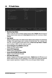
... the CPU fan to run at full speed. (Default: Enabled) GA-GC220 Motherboard - 36 - Current CPU/SYSTEM FAN Speed (RPM) Displays current CPU/system fan speed. CPU Smart FAN Control Enables or disables the CPU fan speed control function. If disabled, CPU fan runs at different speed according to CMOS, and then restart your system. To clear the chassis intrusion status record, set Reset Case Open Status to Enabled, save the settings to the CPU temperature. Current Voltage(V) Vcore/DDR18V/+3.3V/+12V Displays the current system voltages. 2-8 PC Health Status CMOS Setup Utility-Copyright...
... the CPU fan to run at full speed. (Default: Enabled) GA-GC220 Motherboard - 36 - Current CPU/SYSTEM FAN Speed (RPM) Displays current CPU/system fan speed. CPU Smart FAN Control Enables or disables the CPU fan speed control function. If disabled, CPU fan runs at different speed according to CMOS, and then restart your system. To clear the chassis intrusion status record, set Reset Case Open Status to Enabled, save the settings to the CPU temperature. Current Voltage(V) Vcore/DDR18V/+3.3V/+12V Displays the current system voltages. 2-8 PC Health Status CMOS Setup Utility-Copyright...
Manual
Page 37
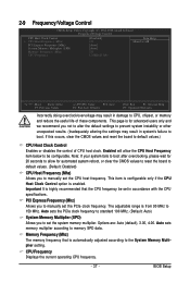
...reset the board to default values. (Default: Disabled) CPU Host Frequency (Mhz) Allows you not to alter the default settings to prevent system instability or other unexpected results. (Inadequately altering the settings may result in damage to CPU, chipset, or memory and reduce the useful life of CPU host clock. 2-9 Frequency/Voltage Control CMOS Setup Utility-Copyright (C) 1984-2008 Award Software Frequency/Voltage Control CPU Host Clock Control x CPU Host Frequency (Mhz) PCI Express Frequency (Mhz) System Memory Multiplier (SPD) Memory Frequency (Mhz) CPU Frequency [Disabled] 133 [Auto...
...reset the board to default values. (Default: Disabled) CPU Host Frequency (Mhz) Allows you not to alter the default settings to prevent system instability or other unexpected results. (Inadequately altering the settings may result in damage to CPU, chipset, or memory and reduce the useful life of CPU host clock. 2-9 Frequency/Voltage Control CMOS Setup Utility-Copyright (C) 1984-2008 Award Software Frequency/Voltage Control CPU Host Clock Control x CPU Host Frequency (Mhz) PCI Express Frequency (Mhz) System Memory Multiplier (SPD) Memory Frequency (Mhz) CPU Frequency [Disabled] 133 [Auto...
Manual
Page 40
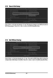
... and press the key. This exits the BIOS Setup without saving the changes made in BIOS Setup to the BIOS Setup Main Menu. Press or to return to the CMOS. This saves the changes to the BIOS Setup Main Menu. 2-14 Exit Without Saving CMOS Setup Utility-Copyright (C) 1984-2008 Award Software ` Standard CMOS Features ` Advanced BIOS Features ` Integrated Peripherals ` Power Management Setup ` PnP/PCI Configurations ` PC Health Status ` Frequency/Voltage Control Esc: Quit F8: Q-Flash Load Fail-Safe Defaults Load Optimized Defaults Set Supervisor Password Quit Without...
... and press the key. This exits the BIOS Setup without saving the changes made in BIOS Setup to the BIOS Setup Main Menu. Press or to return to the CMOS. This saves the changes to the BIOS Setup Main Menu. 2-14 Exit Without Saving CMOS Setup Utility-Copyright (C) 1984-2008 Award Software ` Standard CMOS Features ` Advanced BIOS Features ` Integrated Peripherals ` Power Management Setup ` PnP/PCI Configurations ` PC Health Status ` Frequency/Voltage Control Esc: Quit F8: Q-Flash Load Fail-Safe Defaults Load Optimized Defaults Set Supervisor Password Quit Without...
Manual
Page 41
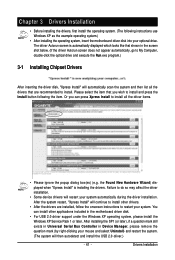
... Serial Bus Controller in the motherboard driver disk. • For USB 2.0 driver support under the Windows XP operating system, please install the Windows XP Service Pack 1 or later. Or you wish to restart your optional drive. Drivers Installation The driver Autorun screen is installing the drivers. Failure to install. Chapter 3 Drivers Installation • Before installing the drivers, first install the operating system. (The following the item. After the system restart, "Xpress Install" will automatically scan the system and then list...
... Serial Bus Controller in the motherboard driver disk. • For USB 2.0 driver support under the Windows XP operating system, please install the Windows XP Service Pack 1 or later. Or you wish to restart your optional drive. Drivers Installation The driver Autorun screen is installing the drivers. Failure to install. Chapter 3 Drivers Installation • Before installing the drivers, first install the operating system. (The following the item. After the system restart, "Xpress Install" will automatically scan the system and then list...
Manual
Page 51
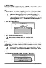
... Enable !! Updating the BIOS When updating the BIOS, choose the location where the BIOS file is complete, press any keEyStCo:Rcoensetitnue F10:Power Off - 51 - Insert the USB flash drive containing the BIOS file into your motherboard model. Unique Features In the main menu of the system reading the BIOS file is saved to a hard drive in RAID/AHCI mode or a hard drive attached to an independent IDE/SATA controller, use the up or down arrow key to access Q-Flash. 2. appears, press to update BIOS?" Select HDD...
... Enable !! Updating the BIOS When updating the BIOS, choose the location where the BIOS file is complete, press any keEyStCo:Rcoensetitnue F10:Power Off - 51 - Insert the USB flash drive containing the BIOS file into your motherboard model. Unique Features In the main menu of the system reading the BIOS file is saved to a hard drive in RAID/AHCI mode or a hard drive attached to an independent IDE/SATA controller, use the up or down arrow key to access Q-Flash. 2. appears, press to update BIOS?" Select HDD...
Manual
Page 57
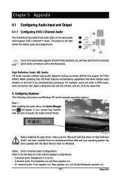
... instructions use Windows XP as the example operating system.) Step 1: After installing the audio driver, the Audio Manager icon will appear in and out) to the following for High Definition Audio" has been installed from the motherboard driver disk and your system tray. HD Audio features multistreaming capabilities that support 44.1KHz/ 48KHz/ 96KHz sampling rate. High Definition Audio (HD Audio) HD Audio includes multiple high quality digital-to access the Audio Control Panel...
... instructions use Windows XP as the example operating system.) Step 1: After installing the audio driver, the Audio Manager icon will appear in and out) to the following for High Definition Audio" has been installed from the motherboard driver disk and your system tray. HD Audio features multistreaming capabilities that support 44.1KHz/ 48KHz/ 96KHz sampling rate. High Definition Audio (HD Audio) HD Audio includes multiple high quality digital-to access the Audio Control Panel...
Manual
Page 63
... I clear the CMOS values? If your motherboard, please go to clear the CMOS values. Plug in the BIOS Setup program. Press to the maximum volume? A: The following Award BIOS beep code descriptions may help you identify possible computer problems. (For reference only.) 1 short: System boots successfully 2 short: CMOS setting error 1 long, 1 short: Memory or motherboard error 1 long, 2 short: Monitor or graphics card error 1 long, 3 short: Keyboard error 1 long, 9 short: BIOS ROM error Continuous long beeps: Graphics card not inserted properly Continuous short beeps: Power error...
... I clear the CMOS values? If your motherboard, please go to clear the CMOS values. Plug in the BIOS Setup program. Press to the maximum volume? A: The following Award BIOS beep code descriptions may help you identify possible computer problems. (For reference only.) 1 short: System boots successfully 2 short: CMOS setting error 1 long, 1 short: Memory or motherboard error 1 long, 2 short: Monitor or graphics card error 1 long, 3 short: Keyboard error 1 long, 9 short: BIOS ROM error Continuous long beeps: Graphics card not inserted properly Continuous short beeps: Power error...


