Manual
Page 1
GA-G31MX-S2 LGA775 socket motherboard for Intel® CoreTM processor family/ Intel® Pentium® processor family/Intel® Celeron® processor family User's Manual Rev. 1002 12ME-G31MXS2-1002R * The WEEE marking on the product indicates this product must not be disposed of with user's other household waste and must be handed over to a designated collection point for the recycling of waste electrical and electronic equipment!! * The WEEE marking applies only in European Union's member states.
GA-G31MX-S2 LGA775 socket motherboard for Intel® CoreTM processor family/ Intel® Pentium® processor family/Intel® Celeron® processor family User's Manual Rev. 1002 12ME-G31MXS2-1002R * The WEEE marking on the product indicates this product must not be disposed of with user's other household waste and must be handed over to a designated collection point for the recycling of waste electrical and electronic equipment!! * The WEEE marking applies only in European Union's member states.
Manual
Page 2
Motherboard GA-G31MX-S2 Jul. 13, 2007 Motherboard GA-G31MX-S2 Jul. 13, 2007
Motherboard GA-G31MX-S2 Jul. 13, 2007 Motherboard GA-G31MX-S2 Jul. 13, 2007
Manual
Page 3
...by GIGA-BYTE TECHNOLOGY CO., LTD. For product-related information, check on our website at: http://www.gigabyte.com.tw Identifying Your Motherboard Revision The revision number on our website. The trademarks mentioned in this manual may be reproduced, copied,...transmitted, or published in this manual may be made by any form or by GIGABYTE without GIGABYTE's prior written permission. GIGABYTE UNITED INC. Check your motherboard looks like this product, GIGABYTE provides the following types of documentations: „ For detailed product information, carefully read...
...by GIGA-BYTE TECHNOLOGY CO., LTD. For product-related information, check on our website at: http://www.gigabyte.com.tw Identifying Your Motherboard Revision The revision number on our website. The trademarks mentioned in this manual may be reproduced, copied,...transmitted, or published in this manual may be made by any form or by GIGABYTE without GIGABYTE's prior written permission. GIGABYTE UNITED INC. Check your motherboard looks like this product, GIGABYTE provides the following types of documentations: „ For detailed product information, carefully read...
Manual
Page 4
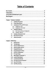
Table of Contents Box Contents ...6 OptionalItems ...6 GA-G31MX-S2 Motherboard Layout 7 Block Diagram ...8 Chapter 1 Hardware Installation 9 1-1 Installation Precautions 9 1-2 Product Specifications 10 1-3 Installing the CPU and CPU Cooler 13 1-3-1 Installing the CPU 13 1-3-2 Installing the CPU ...
Table of Contents Box Contents ...6 OptionalItems ...6 GA-G31MX-S2 Motherboard Layout 7 Block Diagram ...8 Chapter 1 Hardware Installation 9 1-1 Installation Precautions 9 1-2 Product Specifications 10 1-3 Installing the CPU and CPU Cooler 13 1-3-1 Installing the CPU 13 1-3-2 Installing the CPU ...
Manual
Page 6
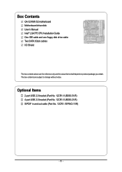
Box Contents GA-G31MX-S2 motherboard Motherboard driver disk User's Manual Intel® LGA775 CPU Installation Guide One IDE cable and one floppy disk drive cable Two SATA 3Gb/s cables I/O Shield The box contents above are subject to change without notice. Optional Items 2-port USB 2.0 bracket (Part No. 12CR1-1UB030-51/R) 4-port USB 2.0 bracket (Part No. 12CR1-1UB030-21/R) S/PDIF in and out cable (Part No. 12CR1-1SPINO-11/R) - 6 - The box contents are for reference only and the actual items shall depend on product package you obtain.
Box Contents GA-G31MX-S2 motherboard Motherboard driver disk User's Manual Intel® LGA775 CPU Installation Guide One IDE cable and one floppy disk drive cable Two SATA 3Gb/s cables I/O Shield The box contents above are subject to change without notice. Optional Items 2-port USB 2.0 bracket (Part No. 12CR1-1UB030-51/R) 4-port USB 2.0 bracket (Part No. 12CR1-1UB030-21/R) S/PDIF in and out cable (Part No. 12CR1-1SPINO-11/R) - 6 - The box contents are for reference only and the actual items shall depend on product package you obtain.
Manual
Page 7
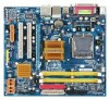
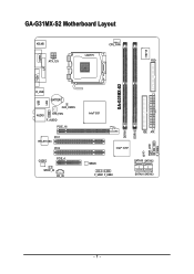
GA-G31MX-S2 Motherboard Layout KB_MS CPU_FAN IT8718 LGA775 ATX_12V FDD GA-G31MX-S2 LPT LAN VGA COMA R_USB BATTERY USB CLR_CMOS AUDIO SYS_FAN F_AUDIO PCIE_16 PCI1 RTL8110SC PCI2 CODEC PCIE_4 SPDIF_IO CD_IN Intel® G31 IDE ATX MBIOS Intel® ICH7 CI SATAII0 SATAII2 F_USB1 F_USB2 SATAII1 SATAII3 DDRII1 DDRII2 PWR_LED F_PANEL - 7 -
GA-G31MX-S2 Motherboard Layout KB_MS CPU_FAN IT8718 LGA775 ATX_12V FDD GA-G31MX-S2 LPT LAN VGA COMA R_USB BATTERY USB CLR_CMOS AUDIO SYS_FAN F_AUDIO PCIE_16 PCI1 RTL8110SC PCI2 CODEC PCIE_4 SPDIF_IO CD_IN Intel® G31 IDE ATX MBIOS Intel® ICH7 CI SATAII0 SATAII2 F_USB1 F_USB2 SATAII1 SATAII3 DDRII1 DDRII2 PWR_LED F_PANEL - 7 -
Manual
Page 9
... procedures: • Prior to installation, do not allow screws to come in a high-temperature environment. • Turning on the motherboard, make sure the power supply voltage has been set according to the internal connectors on the computer power during the installation process can ...become damaged as a motherboard, CPU or memory. Hardware Installation These stickers are required for warranty validation. • Always remove the AC power by your hardware...
... procedures: • Prior to installation, do not allow screws to come in a high-temperature environment. • Turning on the motherboard, make sure the power supply voltage has been set according to the internal connectors on the computer power during the installation process can ...become damaged as a motherboard, CPU or memory. Hardware Installation These stickers are required for warranty validation. • Always remove the AC power by your hardware...
Manual
Page 10
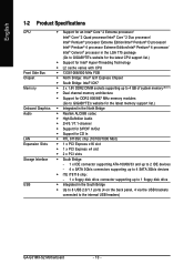
... Edition/Intel® Pentium® 4 processor/ Intel® Celeron® processor in the LGA 775 package (Go to GIGABYTE's website for the latest CPU support list.) Š Support for Intel® Hyper-Threading Technology Š L2 cache varies...memory (Note 1) Š Dual channel memory architecture Š Support for DDR2 800/667 MHz memory modules (Go to GIGABYTE's website for the latest memory support list.) Š Integrated in the North Bridge Š Realtek ALC888 codec Š ...the back panel, 4 via the USB brackets connected to the internal USB headers) GA-G31MX-S2 Motherboard - 10 -
... Edition/Intel® Pentium® 4 processor/ Intel® Celeron® processor in the LGA 775 package (Go to GIGABYTE's website for the latest CPU support list.) Š Support for Intel® Hyper-Threading Technology Š L2 cache varies...memory (Note 1) Š Dual channel memory architecture Š Support for DDR2 800/667 MHz memory modules (Go to GIGABYTE's website for the latest memory support list.) Š Integrated in the North Bridge Š Realtek ALC888 codec Š ...the back panel, 4 via the USB brackets connected to the internal USB headers) GA-G31MX-S2 Motherboard - 10 -
Manual
Page 12
...Š Support for Virtual Dual BIOS Š Norton Internet Security (OEM version) Š Support for Microsoft® Windows® Vista/XP/2000 (Go to GIGABYTE's website for system usage and therefore the actual memory size is reserved for operating system support information.) Š Micro ATX form factor; 24.4cm x 21... architecture, a certain amount of memory size will instead be shown as 3.xx GB during system startup. (Note 2) Available functions in Easytune may differ by motherboard model. GA-G31MX-S2 Motherboard - 12 - For example, 4 GB of memory is less than the stated amount.
...Š Support for Virtual Dual BIOS Š Norton Internet Security (OEM version) Š Support for Microsoft® Windows® Vista/XP/2000 (Go to GIGABYTE's website for system usage and therefore the actual memory size is reserved for operating system support information.) Š Micro ATX form factor; 24.4cm x 21... architecture, a certain amount of memory size will instead be shown as 3.xx GB during system startup. (Note 2) Available functions in Easytune may differ by motherboard model. GA-G31MX-S2 Motherboard - 12 - For example, 4 GB of memory is less than the stated amount.

Manual
Page 13
...Installing the CPU and CPU Cooler Read the following guidelines before you begin to install the CPU: • Make sure that the motherboard supports the CPU. (Go to GIGABYTE's website for the latest CPU support list.) • Always turn on enabling the HT Technology.) 1-3-1 Installing the CPU A. mended... • A chipset that supports HT Technology • An operating system that is not recom- Locate the alignment keys on the motherboard CPU socket and the notches on the CPU Hardware Installation The CPU cannot be set beyond the standard specifications, please do so according to...
...Installing the CPU and CPU Cooler Read the following guidelines before you begin to install the CPU: • Make sure that the motherboard supports the CPU. (Go to GIGABYTE's website for the latest CPU support list.) • Always turn on enabling the HT Technology.) 1-3-1 Installing the CPU A. mended... • A chipset that supports HT Technology • An operating system that is not recom- Locate the alignment keys on the motherboard CPU socket and the notches on the CPU Hardware Installation The CPU cannot be set beyond the standard specifications, please do so according to...

Manual
Page 14
... protective socket cover. GA-G31MX-S2 Motherboard - 14 - Follow the steps below to the CPU. Step 4: Hold the CPU with the socket alignment keys) and gently insert the CPU into position. Step 5: Once the CPU is properly inserted, replace the load plate and push the CPU socket lever back into the motherboard CPU socket. CPU...
... protective socket cover. GA-G31MX-S2 Motherboard - 14 - Follow the steps below to the CPU. Step 4: Hold the CPU with the socket alignment keys) and gently insert the CPU into position. Step 5: Once the CPU is properly inserted, replace the load plate and push the CPU socket lever back into the motherboard CPU socket. CPU...

Manual
Page 15
... 2: Before installing the cooler, note the direction of the arrow sign on the male push pin. (Turning the push pin along the direction of the motherboard. Step 6: Finally, attach the power connector of the installed CPU. If the push pin is inserted as the example cooler.) Step 1: Apply an even and... surface of the CPU cooler to install.) Step 3: Place the cooler atop the CPU, aligning the four push pins through the pin holes on the motherboard. Push down each push pin. English 1-3-2 Installing the CPU Cooler Follow the steps below to correctly install the CPU cooler on the...
... 2: Before installing the cooler, note the direction of the arrow sign on the male push pin. (Turning the push pin along the direction of the motherboard. Step 6: Finally, attach the power connector of the installed CPU. If the push pin is inserted as the example cooler.) Step 1: Apply an even and... surface of the CPU cooler to install.) Step 3: Place the cooler atop the CPU, aligning the four push pins through the pin holes on the motherboard. Push down each push pin. English 1-3-2 Installing the CPU Cooler Follow the steps below to correctly install the CPU cooler on the...
Manual
Page 16
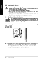
...the memory, switch the direction. 1-4-1 Dual Channel Memory Configuration This motherboard provides two DDR2 memory sockets and supports Dual Channel Technology. Dual Channel mode cannot be used . (Go to GIGABYTE's website for the latest memory support list.) • Always turn... limitation, read the following guidelines before installing the memory to prevent hardware damage. • Memory modules have a foolproof design. GA-G31MX-S2 Motherboard - 16 - Enabling Dual Channel memory mode will automatically detect the specifications and capacity of the same capacity, brand, speed, ...
...the memory, switch the direction. 1-4-1 Dual Channel Memory Configuration This motherboard provides two DDR2 memory sockets and supports Dual Channel Technology. Dual Channel mode cannot be used . (Go to GIGABYTE's website for the latest memory support list.) • Always turn... limitation, read the following guidelines before installing the memory to prevent hardware damage. • Memory modules have a foolproof design. GA-G31MX-S2 Motherboard - 16 - Enabling Dual Channel memory mode will automatically detect the specifications and capacity of the same capacity, brand, speed, ...
Manual
Page 17
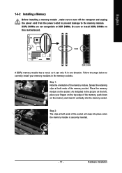
... the socket will snap into the memory socket. Spread the retaining clips at both ends of the memory module. Place the memory module on this motherboard. English 1-4-2 Installing a Memory Before installing a memory module , make sure to turn off the computer and unplug the power cord from the power outlet to prevent...
... the socket will snap into the memory socket. Spread the retaining clips at both ends of the memory module. Place the memory module on this motherboard. English 1-4-2 Installing a Memory Before installing a memory module , make sure to turn off the computer and unplug the power cord from the power outlet to prevent...
Manual
Page 18
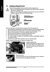
... expansion card in the expansion slot. 1. Make sure the metal contacts on the card are completely inserted into the PCI Express x16 slot. GA-G31MX-S2 Motherboard - 18 - Locate an expansion slot that came with a screw. 5. If necessary, go to BIOS Setup to correctly install your expansion ... an Expansion Card Read the following guidelines before installing an expansion card to install an expansion card: • Make sure the motherboard supports the expansion card. Carefully read the manual that supports your computer. Secure the card's metal bracket to release the card and...
... expansion card in the expansion slot. 1. Make sure the metal contacts on the card are completely inserted into the PCI Express x16 slot. GA-G31MX-S2 Motherboard - 18 - Locate an expansion slot that came with a screw. 5. If necessary, go to BIOS Setup to correctly install your expansion ... an Expansion Card Read the following guidelines before installing an expansion card to install an expansion card: • Make sure the motherboard supports the expansion card. Carefully read the manual that supports your computer. Secure the card's metal bracket to release the card and...
Manual
Page 19
... not established • When removing the cable connected to a back panel connector, first remove the cable from your device and then remove it from the motherboard. • When removing the cable, pull it side to side to this port for USB devices such as an USB keyboard/mouse, USB printer, USB...
... not established • When removing the cable connected to a back panel connector, first remove the cable from your device and then remove it from the motherboard. • When removing the cable, pull it side to side to this port for USB devices such as an USB keyboard/mouse, USB printer, USB...
Manual
Page 20
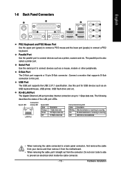
... default Mic in Chapter 5, "Configuring 2/4/5.1/7.1-Channel Audio." Line In Jack (Blue) The default line in jack. Line Out Jack (Green) The default line out jack. GA-G31MX-S2 Motherboard - 20 - Side Speaker Out Jack (Gray) Use this jack. Only microphones still MUST be connected to this audio jack to the instructions on setting up...
... default Mic in Chapter 5, "Configuring 2/4/5.1/7.1-Channel Audio." Line In Jack (Blue) The default line in jack. Line Out Jack (Green) The default line out jack. GA-G31MX-S2 Motherboard - 20 - Side Speaker Out Jack (Gray) Use this jack. Only microphones still MUST be connected to this audio jack to the instructions on setting up...
Manual
Page 21
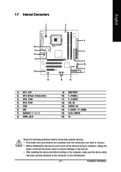
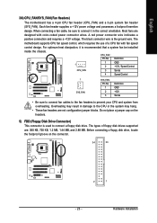
... devices and your devices are compliant with the connectors you wish to connect. • Before installing the devices, be sure to the connector on the motherboard. - 21 - Hardware Installation English 1-7 Internal Connectors 1 3 15 9 11 4 13 12 1) ATX_12V 2) ATX (Power Connector) 3) CPU_FAN 4) SYS_FAN 5) FDD 6) IDE 7) SATAII0 / 1 / 2 / 3 8) PWR_LED 5 2 6 10 8 7 14 16 9) BATTERY 10...
... devices and your devices are compliant with the connectors you wish to connect. • Before installing the devices, be sure to the connector on the motherboard. - 21 - Hardware Installation English 1-7 Internal Connectors 1 3 15 9 11 4 13 12 1) ATX_12V 2) ATX (Power Connector) 3) CPU_FAN 4) SYS_FAN 5) FDD 6) IDE 7) SATAII0 / 1 / 2 / 3 8) PWR_LED 5 2 6 10 8 7 14 16 9) BATTERY 10...
Manual
Page 22
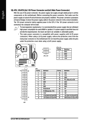
... computer will not start. • To meet expansion requirements, it is turned off and all the components on the motherboard. Connect the power supply cable to an unstable or unbootable system. • The main power connector is used (400W...the protective cover when using a 2x12 power supply, remove the protective cover from the main power connector on the motherboard. If a power supply is compatible with power supplies with 2x10 power connectors. The 12V power connector mainly supplies ... +5V +5V +5V (Only for 2x12-pin ATX) GND (Only for 2x12-pin ATX) GA-G31MX-S2 Motherboard - 22 -
... computer will not start. • To meet expansion requirements, it is turned off and all the components on the motherboard. Connect the power supply cable to an unstable or unbootable system. • The main power connector is used (400W...the protective cover when using a 2x12 power supply, remove the protective cover from the main power connector on the motherboard. If a power supply is compatible with power supplies with 2x10 power connectors. The 12V power connector mainly supplies ... +5V +5V +5V (Only for 2x12-pin ATX) GND (Only for 2x12-pin ATX) GA-G31MX-S2 Motherboard - 22 -
Manual
Page 23
...system from overheating. Hardware Installation When connecting a fan cable, be installed inside the chassis. English 3/4) CPU_FAN/SYS_FAN (Fan Headers) The motherboard has a 4-pin CPU fan header (CPU_FAN) and a 3-pin system fan header (SYS_FAN). Do not place a jumper cap on ...voltage and possesses a foolproof insertion design. A red power connector wire indicates a positive connection and requires a +12V voltage. The motherboard supports CPU fan speed control, which requires the use of floppy disk drives supported are not configuration jumper blocks. Definition 1 1 GND...
...system from overheating. Hardware Installation When connecting a fan cable, be installed inside the chassis. English 3/4) CPU_FAN/SYS_FAN (Fan Headers) The motherboard has a 4-pin CPU fan header (CPU_FAN) and a 3-pin system fan header (SYS_FAN). Do not place a jumper cap on ...voltage and possesses a foolproof insertion design. A red power connector wire indicates a positive connection and requires a +12V voltage. The motherboard supports CPU fan speed control, which requires the use of floppy disk drives supported are not configuration jumper blocks. Definition 1 1 GND...


