Manual
Page 4
... ...6 GA-G31MX-S2 Motherboard Layout 7 Block Diagram ...8 Chapter 1 Hardware Installation 9 1-1 Installation Precautions 9 1-2 Product Specifications 10 1-3 Installing the CPU and CPU Cooler 13 1-3-1 Installing the CPU 13 1-3-2 Installing the CPU Cooler 15 1-4 Installing the Memory 16 1-4-1 Dual Channel Memory Configuration 16 1-4-2 Installing a Memory 17 1-5 Installing an Expansion Card 18 1-6 Back Panel Connectors 19 1-7 Internal Connectors 21 Chapter 2 BIOS Setup 31 2-1 Startup Screen 32 2-2 The Main Menu 33 2-3 Standard CMOS Features 35 2-4 Advanced BIOS Features...
... ...6 GA-G31MX-S2 Motherboard Layout 7 Block Diagram ...8 Chapter 1 Hardware Installation 9 1-1 Installation Precautions 9 1-2 Product Specifications 10 1-3 Installing the CPU and CPU Cooler 13 1-3-1 Installing the CPU 13 1-3-2 Installing the CPU Cooler 15 1-4 Installing the Memory 16 1-4-1 Dual Channel Memory Configuration 16 1-4-2 Installing a Memory 17 1-5 Installing an Expansion Card 18 1-6 Back Panel Connectors 19 1-7 Internal Connectors 21 Chapter 2 BIOS Setup 31 2-1 Startup Screen 32 2-2 The Main Menu 33 2-3 Standard CMOS Features 35 2-4 Advanced BIOS Features...
Manual
Page 10
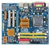
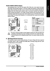
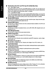
... In Š RTL 8110SC chip (10/100/1000 Mbit) Š 1 x PCI Express x16 slot Š 1 x PCI Express x4 slot Š 2 x PCI slots Š South Bridge: - 1 x IDE connector supporting ATA-100/66/33 and up to 2 IDE devices - 4 x SATA 3Gb/s connectors supporting up to 4 SATA 3Gb/s devices Š iTE IT8718 chip: - 1 x floppy disk drive connector supporting up to 1 floppy disk drive Š Integrated in the South Bridge Š Up to 8 USB 2.0/1.1 ports (4 on the back panel, 4 via the USB brackets connected to the internal USB headers) GA-G31MX-S2 Motherboard - 10 -
... In Š RTL 8110SC chip (10/100/1000 Mbit) Š 1 x PCI Express x16 slot Š 1 x PCI Express x4 slot Š 2 x PCI slots Š South Bridge: - 1 x IDE connector supporting ATA-100/66/33 and up to 2 IDE devices - 4 x SATA 3Gb/s connectors supporting up to 4 SATA 3Gb/s devices Š iTE IT8718 chip: - 1 x floppy disk drive connector supporting up to 1 floppy disk drive Š Integrated in the South Bridge Š Up to 8 USB 2.0/1.1 ports (4 on the back panel, 4 via the USB brackets connected to the internal USB headers) GA-G31MX-S2 Motherboard - 10 -
Manual
Page 16
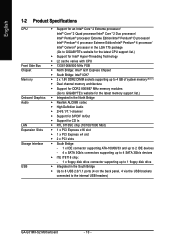
... following guidelines before installing the memory to prevent hardware damage. • Memory modules have a foolproof design. It is installed, the BIOS will double the original memory bandwidth. Enabling Dual Channel memory mode will automatically detect the specifications and capacity of the same capacity, brand, speed, and chips be enabled if only one DDR2 memory module is installed. 2. GA-G31MX-S2 Motherboard - 16 - Dual Channel mode cannot be used . If you begin to install the memory: • Make...
... following guidelines before installing the memory to prevent hardware damage. • Memory modules have a foolproof design. It is installed, the BIOS will double the original memory bandwidth. Enabling Dual Channel memory mode will automatically detect the specifications and capacity of the same capacity, brand, speed, and chips be enabled if only one DDR2 memory module is installed. 2. GA-G31MX-S2 Motherboard - 16 - Dual Channel mode cannot be used . If you begin to install the memory: • Make...
Manual
Page 18
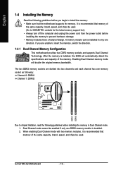
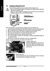
... the slot. 3. After installing all expansion cards, replace the chassis cover(s). 6. Install the driver provided with a screw. 5. GA-G31MX-S2 Motherboard - 18 - Secure the card's metal bracket to release the card and then pull the card straight up from the slot. If necessary, go to BIOS Setup to correctly install your operating system. PCI Express x16 Slot PCI Slot PCI Express x4 Slot Follow the steps below to make any required BIOS changes for your expansion card. • Always turn...
... the slot. 3. After installing all expansion cards, replace the chassis cover(s). 6. Install the driver provided with a screw. 5. GA-G31MX-S2 Motherboard - 18 - Secure the card's metal bracket to release the card and then pull the card straight up from the slot. If necessary, go to BIOS Setup to correctly install your operating system. PCI Express x16 Slot PCI Slot PCI Express x4 Slot Follow the steps below to make any required BIOS changes for your expansion card. • Always turn...
Manual
Page 23
... orientation. Hardware Installation Each fan header supplies a +12V power voltage and possesses a foolproof insertion design. Overheating may hang. • These fan headers are not configuration jumper blocks. When connecting a fan cable, be installed inside the chassis. The types of a CPU fan with color-coded power connector wires. For optimum heat dissipation, it is recommended that a system fan be sure to connect it in damage to prevent your CPU and system from overheating. Before connecting a floppy disk drive, locate the foolproof...
... orientation. Hardware Installation Each fan header supplies a +12V power voltage and possesses a foolproof insertion design. Overheating may hang. • These fan headers are not configuration jumper blocks. When connecting a fan cable, be installed inside the chassis. The types of a CPU fan with color-coded power connector wires. For optimum heat dissipation, it is recommended that a system fan be sure to connect it in damage to prevent your CPU and system from overheating. Before connecting a floppy disk drive, locate the foolproof...
Manual
Page 26
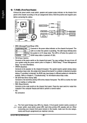
... this header according to the power status indicator on the chassis front panel. The system reports system startup status by chassis. Speaker Connector Power Switch Message LED/ Power/ Sleep LED SPEAK- 20 19 SPEAK+ PWPW+ MSGMSG+ 21 NCRES+ RES- GA-G31MX-S2 Motherboard - 26 - You may configure the way to turn off (S5). • PW (Power Switch): Connects to the hard drive activity LED on the chassis front panel. Note the positive and negative pins before connecting the cables. The LED...
... this header according to the power status indicator on the chassis front panel. The system reports system startup status by chassis. Speaker Connector Power Switch Message LED/ Power/ Sleep LED SPEAK- 20 19 SPEAK+ PWPW+ MSGMSG+ 21 NCRES+ RES- GA-G31MX-S2 Motherboard - 26 - You may configure the way to turn off (S5). • PW (Power Switch): Connects to the hard drive activity LED on the chassis front panel. Note the positive and negative pins before connecting the cables. The LED...

Manual
Page 29
... jumper cap from the power outlet before clearing the CMOS values. • After clearing the CMOS values and before turning on the two pins to temporarily short the two pins or use a metal object like a screwdriver to Chapter 2, "BIOS Setup," for a few seconds. Failure to do so may cause damage to the motherboard. • After system restart, go to BIOS Setup to load factory defaults (select Load Optimized Defaults) or manually configure the BIOS settings...
... jumper cap from the power outlet before clearing the CMOS values. • After clearing the CMOS values and before turning on the two pins to temporarily short the two pins or use a metal object like a screwdriver to Chapter 2, "BIOS Setup," for a few seconds. Failure to do so may cause damage to the motherboard. • After system restart, go to BIOS Setup to load factory defaults (select Load Optimized Defaults) or manually configure the BIOS settings...
Manual
Page 31
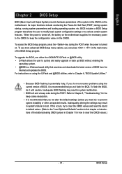
... upgrade or back up BIOS without entering the operating system. • @BIOS is a Windows-based utility that allows the user to modify basic system configuration settings or to activate certain system features. If this occurs, try to clear the CMOS values and reset the board to default values. (Refer to the "Load Optimized Defaults" section in this chapter or introductions of the battery/clearing CMOS jumper in Chapter 1 for the beep codes...
... upgrade or back up BIOS without entering the operating system. • @BIOS is a Windows-based utility that allows the user to modify basic system configuration settings or to activate certain system features. If this occurs, try to clear the CMOS values and reset the board to default values. (Refer to the "Load Optimized Defaults" section in this chapter or introductions of the battery/clearing CMOS jumper in Chapter 1 for the beep codes...
Manual
Page 34
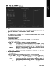
... CMOS Features Use this menu to configure the system time and date, hard drive types, floppy disk drive types, and the type of errors that stop the system boot, etc. „ Advanced BIOS Features Use this menu to configure the device boot order, advanced features available on the CPU, and the primary display adapter. „ Integrated Peripherals Use this menu to configure all peripheral devices, such as IDE, SATA, USB, integrated audio, and integrated LAN, etc. „ Power Management Setup Use this menu to configure all changes...
... CMOS Features Use this menu to configure the system time and date, hard drive types, floppy disk drive types, and the type of errors that stop the system boot, etc. „ Advanced BIOS Features Use this menu to configure the device boot order, advanced features available on the CPU, and the primary display adapter. „ Integrated Peripherals Use this menu to configure all peripheral devices, such as IDE, SATA, USB, integrated audio, and integrated LAN, etc. „ Power Management Setup Use this menu to configure all changes...
Manual
Page 35
...] Drive A Floppy 3 Mode Support [1.44M, 3.5"] [Disabled] Halt On [All, But Keyboard] Base Memory Extended Memory Total Memory 640K 510M 512M KLJI: Move Enter: Select F5: Previous Values +/-/PU/PD: Value F10: Save F6: Fail-Safe Defaults ESC: Exit F1: General Help F7: Optimized Defaults Date Sets the system date. Access Mode Sets the hard drive access mode. IDE Channel 0 Master/Slave Configure your IDE/SATA devices using one of the device during the POST. (Default) If no IDE/SATA devices are : Auto (default), CHS, LBA, Large. Options...
...] Drive A Floppy 3 Mode Support [1.44M, 3.5"] [Disabled] Halt On [All, But Keyboard] Base Memory Extended Memory Total Memory 640K 510M 512M KLJI: Move Enter: Select F5: Previous Values +/-/PU/PD: Value F10: Save F6: Fail-Safe Defaults ESC: Exit F1: General Help F7: Optimized Defaults Date Sets the system date. Access Mode Sets the hard drive access mode. IDE Channel 0 Master/Slave Configure your IDE/SATA devices using one of the device during the POST. (Default) If no IDE/SATA devices are : Auto (default), CHS, LBA, Large. Options...

Manual
Page 37
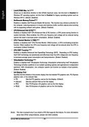
... system boots, or only when you install a CPU that supports this menu when finished. After configuring this item, set the password(s) under the Set Supervisor/User Password item in the BIOS Main Menu. Capability CPU Hyper-Threading (Note) Limit CPUID Max. Options are: Floppy, LS120, Hard Disk, CDROM, ZIP, USB-FDD, USB-ZIP, USB-CDROM, USB-HDD, LAN, Disabled. HDD S.M.A.R.T. For more information about Intel CPUs' unique features, please visit Intel's website. - 37 - BIOS Setup Use the up or down arrow key...
... system boots, or only when you install a CPU that supports this menu when finished. After configuring this item, set the password(s) under the Set Supervisor/User Password item in the BIOS Main Menu. Capability CPU Hyper-Threading (Note) Limit CPUID Max. Options are: Floppy, LS120, Hard Disk, CDROM, ZIP, USB-FDD, USB-ZIP, USB-CDROM, USB-HDD, LAN, Disabled. HDD S.M.A.R.T. For more information about Intel CPUs' unique features, please visit Intel's website. - 37 - BIOS Setup Use the up or down arrow key...
Manual
Page 38
... working with its supporting software and system. (Default: Enabled) CPU Enhanced Halt (C1E) (Note) Enables or disables Intel® CPU Enhanced Halt (C1E) function, a CPU power-saving function in independent partitions. This function may enhance protection for Windows XP operating system; GA-G31MX-S2 Motherboard - 38 - Set this item to Disabled for the computer, reducing exposure to Enabled for legacy operating system such as the first display. set this feature. PEG2 Sets PCI Express x4 graphics card...
... working with its supporting software and system. (Default: Enabled) CPU Enhanced Halt (C1E) (Note) Enables or disables Intel® CPU Enhanced Halt (C1E) function, a CPU power-saving function in independent partitions. This function may enhance protection for Windows XP operating system; GA-G31MX-S2 Motherboard - 38 - Set this item to Disabled for the computer, reducing exposure to Enabled for legacy operating system such as the first display. set this feature. PEG2 Sets PCI Express x4 graphics card...

Manual
Page 39
... or not a PCI Express card is the total amount of system memory allocated solely for display. On-Chip Frame Buffer Size Frame buffer size is installed. English Onboard VGA Enables or disables the onboard VGA function. MS-DOS, for example, will use only this item to Always Enable. Options are: 8MB+1~2MB for GTT (default), 1MB+1~2MB for GTT. - 39 - If you wish to set up a dual view configuration, set this memory for the onboard graphics controller.
... or not a PCI Express card is the total amount of system memory allocated solely for display. On-Chip Frame Buffer Size Frame buffer size is installed. English Onboard VGA Enables or disables the onboard VGA function. MS-DOS, for example, will use only this item to Always Enable. Options are: 8MB+1~2MB for GTT (default), 1MB+1~2MB for GTT. - 39 - If you wish to set up a dual view configuration, set this memory for the onboard graphics controller.
Manual
Page 40
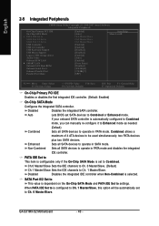
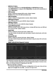
.../Slave. GA-G31MX-S2 Motherboard - 40 - PATA IDE Set to This item is configurable only if the On-Chip SATA Mode is dependent on the On-Chip SATA Mode and PATA IDE Set to Ch. 1 Master/Slave. Auto Lets BIOS set to Ch. 1 Master/Slave, this option will be used simultaneously: two PATA devices Enhanced plus two SATA devices. Non-Combined Sets all SATA devices to USB Controller USB 2.0 Controller USB Keyboard Support USB Mouse Support Legacy USB storage detect Azalia Codec Onboard H/W LAN ` SMART LAN Onboard LAN Boot ROM Onboard Serial Port 1 Onboard Parallel Port Parallel Port Mode...
.../Slave. GA-G31MX-S2 Motherboard - 40 - PATA IDE Set to This item is configurable only if the On-Chip SATA Mode is dependent on the On-Chip SATA Mode and PATA IDE Set to Ch. 1 Master/Slave. Auto Lets BIOS set to Ch. 1 Master/Slave, this option will be used simultaneously: two PATA devices Enhanced plus two SATA devices. Non-Combined Sets all SATA devices to USB Controller USB 2.0 Controller USB Keyboard Support USB Mouse Support Legacy USB storage detect Azalia Codec Onboard H/W LAN ` SMART LAN Onboard LAN Boot ROM Onboard Serial Port 1 Onboard Parallel Port Parallel Port Mode...
Manual
Page 41
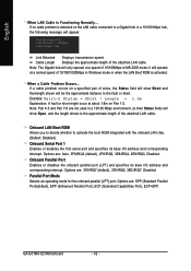
... integrated USB 2.0 controller. (Default: Enabled) USB Keyboard Support Allows USB keyboard to be used in MS-DOS. (Default: Disabled) Legacy USB storage detect Determines whether to detect USB storage devices, including USB flash drives and USB hard drives during the POST. (Default: Enabled) Azalia Codec Enables or disables the onboard audio function. (Default: Auto) If you wish to install a 3rd party add-in network card instead of the attached LAN cable. SMART LAN (LAN Cable Diagnostic Function) CMOS Setup Utility-Copyright (C) 1984-2007 Award Software SMART LAN Start detecting at Port...
... integrated USB 2.0 controller. (Default: Enabled) USB Keyboard Support Allows USB keyboard to be used in MS-DOS. (Default: Disabled) Legacy USB storage detect Determines whether to detect USB storage devices, including USB flash drives and USB hard drives during the POST. (Default: Enabled) Azalia Codec Enables or disables the onboard audio function. (Default: Auto) If you wish to install a 3rd party add-in network card instead of the attached LAN cable. SMART LAN (LAN Cable Diagnostic Function) CMOS Setup Utility-Copyright (C) 1984-2007 Award Software SMART LAN Start detecting at Port...
Manual
Page 42
... When LAN Cable Is Functioning Normally... GA-G31MX-S2 Motherboard - 42 - it will operate at a normal speed of wires, the Status field will show Open, and the length shown is detected on the LAN cable connected to a Gigabit hub or a 10/100 Mbps hub, the following message will be the approximate distance to activate the boot ROM integrated with the onboard LAN chip. (Default: Disabled) Onboard Serial Port 1 Enables or disables the first serial port...
... When LAN Cable Is Functioning Normally... GA-G31MX-S2 Motherboard - 42 - it will operate at a normal speed of wires, the Status field will show Open, and the length shown is detected on the LAN cable connected to a Gigabit hub or a 10/100 Mbps hub, the following message will be the approximate distance to activate the boot ROM integrated with the onboard LAN chip. (Default: Disabled) Onboard Serial Port 1 Enables or disables the first serial port...
Manual
Page 47
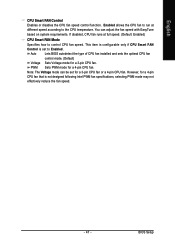
...Auto Lets BIOS autodetect the type of CPU fan installed and sets the optimal CPU fan control mode. (Default) Voltage Sets Voltage mode for a 4-pin CPU fan. Note: The Voltage mode can adjust the fan speed with EasyTune based on system requirements. BIOS Setup English CPU Smart FAN Control Enables or disables the CPU fan speed control function. If disabled, CPU fan runs at different speed according to Enabled. However, for a 4-pin CPU fan that is set for a 3-pin CPU fan or a 4-pin CPU fan. You can be set to the CPU temperature. PWM Sets PWM mode for a 3-pin CPU...
...Auto Lets BIOS autodetect the type of CPU fan installed and sets the optimal CPU fan control mode. (Default) Voltage Sets Voltage mode for a 4-pin CPU fan. Note: The Voltage mode can adjust the fan speed with EasyTune based on system requirements. BIOS Setup English CPU Smart FAN Control Enables or disables the CPU fan speed control function. If disabled, CPU fan runs at different speed according to Enabled. However, for a 4-pin CPU fan that is set for a 3-pin CPU fan or a 4-pin CPU fan. You can be set to the CPU temperature. PWM Sets PWM mode for a 3-pin CPU...
Manual
Page 48
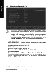
...graphics chip and memory. mode based on system configurations. GA-G31MX-S2 Motherboard - 48 - English 2-9 MB Intelligent Tweaker(M.I.T.) CMOS Setup Utility-Copyright (C) 1984-2007 Award Software MB Intelligent Tweaker(M.I.T.) Robust Graphics Booster CPU Clock Ratio (Note) CPU Host Clock Control x CPU Host Frequency (Mhz) PCI Express Frequency (Mhz) Performance Enhance System Memory Multiplier (SPD) Memory Frequency (Mhz) 667 High Speed DRAM DLL Settings ******** System Voltage Optimized System Voltage Control DDR2 OverVoltage Control FSB OverVoltage Control CPU Voltage Control Normal CPU...
...graphics chip and memory. mode based on system configurations. GA-G31MX-S2 Motherboard - 48 - English 2-9 MB Intelligent Tweaker(M.I.T.) CMOS Setup Utility-Copyright (C) 1984-2007 Award Software MB Intelligent Tweaker(M.I.T.) Robust Graphics Booster CPU Clock Ratio (Note) CPU Host Clock Control x CPU Host Frequency (Mhz) PCI Express Frequency (Mhz) Performance Enhance System Memory Multiplier (SPD) Memory Frequency (Mhz) 667 High Speed DRAM DLL Settings ******** System Voltage Optimized System Voltage Control DDR2 OverVoltage Control FSB OverVoltage Control CPU Voltage Control Normal CPU...
Manual
Page 53
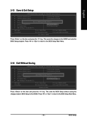
... & Exit Setup F11: Save CMOS to BIOS F12: Load CMOS from BIOS Save Data to CMOS Press on this item and press the key. BIOS Setup Press or to return to the BIOS Setup Main Menu. 2-14 Exit Without Saving CMOS Setup Utility-Copyright (C) 1984-2007 Award Software ` Standard CMOS Features Load Fail-Safe Defaults ` Advanced BIOS Features Load Optimized Defaults ` Integrated Peripherals Set Supervisor Password ` Power Management Setup Quit Without Saving (SYe/tNU)?seNr Password ` PnP/PCI Configurations Save & Exit Setup ` PC Health...
... & Exit Setup F11: Save CMOS to BIOS F12: Load CMOS from BIOS Save Data to CMOS Press on this item and press the key. BIOS Setup Press or to return to the BIOS Setup Main Menu. 2-14 Exit Without Saving CMOS Setup Utility-Copyright (C) 1984-2007 Award Software ` Standard CMOS Features Load Fail-Safe Defaults ` Advanced BIOS Features Load Optimized Defaults ` Integrated Peripherals Set Supervisor Password ` Power Management Setup Quit Without Saving (SYe/tNU)?seNr Password ` PnP/PCI Configurations Save & Exit Setup ` PC Health...

Manual
Page 79
.... Plug in Chapter 1 to short the jumper to enter BIOS Setup during the POST mean? A: The following Award BIOS beep code descriptions may help you identify possible computer problems. (For reference only.) 1 short: System boots successfully 2 short: CMOS setting error 1 long, 1 short: Memory or motherboard error 1 long, 2 short: Monitor or graphics card error 1 long, 3 short: Keyboard error 1 long, 9 short: BIOS ROM error Continuous long beeps: Graphics card not inserted properly Continuous short beeps: Power error - 79 - Q: What do I have this jumper, refer to the instructions...
.... Plug in Chapter 1 to short the jumper to enter BIOS Setup during the POST mean? A: The following Award BIOS beep code descriptions may help you identify possible computer problems. (For reference only.) 1 short: System boots successfully 2 short: CMOS setting error 1 long, 1 short: Memory or motherboard error 1 long, 2 short: Monitor or graphics card error 1 long, 3 short: Keyboard error 1 long, 9 short: BIOS ROM error Continuous long beeps: Graphics card not inserted properly Continuous short beeps: Power error - 79 - Q: What do I have this jumper, refer to the instructions...


