Manual
Page 1
GA-G31-S3G LGA775 socket motherboard for Intel® CoreTM processor family/ Intel® Pentium® processor family/Intel® Celeron® processor family User's Manual Rev. 1001 12ME-G31S3G-1001R
GA-G31-S3G LGA775 socket motherboard for Intel® CoreTM processor family/ Intel® Pentium® processor family/Intel® Celeron® processor family User's Manual Rev. 1001 12ME-G31S3G-1001R

Manual
Page 2
Motherboard GA-G31-S3G Feb. 9, 2009 Motherboard GA-G31-S3G Feb. 9, 2009
Motherboard GA-G31-S3G Feb. 9, 2009 Motherboard GA-G31-S3G Feb. 9, 2009
Manual
Page 4
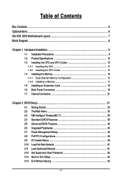
Table of Contents Box Contents ...6 OptionalItems ...6 GA-G31-S3G Motherboard Layout 7 Block Diagram ...8 Chapter 1 Hardware Installation 9 1-1 Installation Precautions 9 1-2 Product Specifications 10 1-3 Installing the CPU and CPU Cooler 13 1-3-1 Installing the CPU 13 1-3-2 Installing the ...
Table of Contents Box Contents ...6 OptionalItems ...6 GA-G31-S3G Motherboard Layout 7 Block Diagram ...8 Chapter 1 Hardware Installation 9 1-1 Installation Precautions 9 1-2 Product Specifications 10 1-3 Installing the CPU and CPU Cooler 13 1-3-1 Installing the CPU 13 1-3-2 Installing the ...
Manual
Page 6
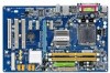
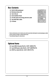
Box Contents GA-G31-S3G motherboard Motherboard driver disk User's Manual Quick Installation Guide One IDE cable and one floppy disk drive cable Two SATA 3Gb/s cables I/O Shield • The box contents above are subject to change without notice. • The motherboard image is for reference only and the actual items shall depend on product package you obtain. Optional Items 2-port USB 2.0 bracket (Part No. 12CR1-1UB030-5*R) 2-port SATA power cable (Part No. 12CF1-2SERPW-0*R) S/PDIF out cable (Part No. 12CR1-1SPOUT-0*R) - 6 - The box contents are for reference only.
Box Contents GA-G31-S3G motherboard Motherboard driver disk User's Manual Quick Installation Guide One IDE cable and one floppy disk drive cable Two SATA 3Gb/s cables I/O Shield • The box contents above are subject to change without notice. • The motherboard image is for reference only and the actual items shall depend on product package you obtain. Optional Items 2-port USB 2.0 bracket (Part No. 12CR1-1UB030-5*R) 2-port SATA power cable (Part No. 12CF1-2SERPW-0*R) S/PDIF out cable (Part No. 12CR1-1SPOUT-0*R) - 6 - The box contents are for reference only.
Manual
Page 7
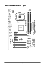
GA-G31-S3G Motherboard Layout KB_MS ATX_12V LGA775 CPU_FAN VGA COMA LPT USB R_USB LAN GA-G31-S3G ATX IDE AUDIO F_AUDIO RTL8111C IT8718 CODEC PCIE_1 PCIE_16 PCIE_2 PCIE_3 CD_IN SPDIF_O PCI1 PCI2 PCI3 Intel® G31 BATTERY Intel® ICH7 SATAII2 SATAII3 CLR_CMOS F_USB1 F_USB2 SATAII0 MBIOS FDD SYS_FAN CI SATAII1 DDRII1 DDRII2 PWR_LED F_PANEL - 7 -
GA-G31-S3G Motherboard Layout KB_MS ATX_12V LGA775 CPU_FAN VGA COMA LPT USB R_USB LAN GA-G31-S3G ATX IDE AUDIO F_AUDIO RTL8111C IT8718 CODEC PCIE_1 PCIE_16 PCIE_2 PCIE_3 CD_IN SPDIF_O PCI1 PCI2 PCI3 Intel® G31 BATTERY Intel® ICH7 SATAII2 SATAII3 CLR_CMOS F_USB1 F_USB2 SATAII0 MBIOS FDD SYS_FAN CI SATAII1 DDRII1 DDRII2 PWR_LED F_PANEL - 7 -
Manual
Page 10
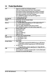
.../Intel® Pentium® 4 processor/ Intel® Celeron® processor in the LGA 775 package (Go to GIGABYTE's website for the latest CPU support list.) L2 cache varies with CPU 1333/1066/800 MHz FSB &#... (Note 1) Dual channel memory architecture Support for DDR2 1066/800/667 MHz memory modules (Go to GIGABYTE's website for the latest memory support list.) Realtek ALC662 codec High Definition Audio 2/4/5.1-channel &#... the back panel, 4 via the USB brackets connected to the internal USB headers) GA-G31-S3G Motherboard - 10 -
.../Intel® Pentium® 4 processor/ Intel® Celeron® processor in the LGA 775 package (Go to GIGABYTE's website for the latest CPU support list.) L2 cache varies with CPU 1333/1066/800 MHz FSB &#... (Note 1) Dual channel memory architecture Support for DDR2 1066/800/667 MHz memory modules (Go to GIGABYTE's website for the latest memory support list.) Realtek ALC662 codec High Definition Audio 2/4/5.1-channel &#... the back panel, 4 via the USB brackets connected to the internal USB headers) GA-G31-S3G Motherboard - 10 -
Manual
Page 12
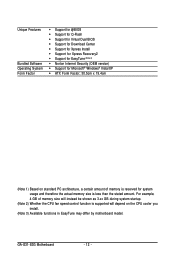
GA-G31-S3G Motherboard - 12 - For example, 4 GB of memory size will instead be shown as 3.xx GB during system startup. (Note 2) Whether the CPU fan speed control ...
GA-G31-S3G Motherboard - 12 - For example, 4 GB of memory size will instead be shown as 3.xx GB during system startup. (Note 2) Whether the CPU fan speed control ...
Manual
Page 14
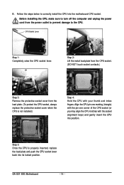
Step 5: Once the CPU is not installed.) Step 4: Hold the CPU with the socket alignment keys) and gently insert the CPU into position. GA-G31-S3G Motherboard - 14 - Follow the steps below to turn off the computer and unplug the power cord from the load plate. (To protect the CPU socket, ...
Step 5: Once the CPU is not installed.) Step 4: Hold the CPU with the socket alignment keys) and gently insert the CPU into position. GA-G31-S3G Motherboard - 14 - Follow the steps below to turn off the computer and unplug the power cord from the load plate. (To protect the CPU socket, ...
Manual
Page 16
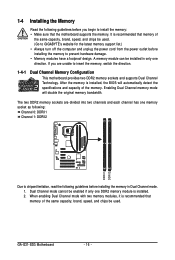
... to GIGABYTE's website for the latest memory support list.) • Always turn off the computer and unplug the power cord from the power outlet before you are divided into two channels and each channel has one direction. When enabling Dual Channel mode with two memory modules, it is installed. 2. GA-G31-S3G Motherboard - 16...
... to GIGABYTE's website for the latest memory support list.) • Always turn off the computer and unplug the power cord from the power outlet before you are divided into two channels and each channel has one direction. When enabling Dual Channel mode with two memory modules, it is installed. 2. GA-G31-S3G Motherboard - 16...
Manual
Page 18
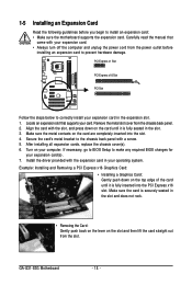
... metal contacts on the slot and then lift the card straight out from the slot. If necessary, go to BIOS Setup to prevent hardware damage. GA-G31-S3G Motherboard - 18 - Install the driver provided with your operating system. After installing all expansion cards, replace the chassis cover(s). 6. 1-5 Installing an Expansion Card Read the...
... metal contacts on the slot and then lift the card straight out from the slot. If necessary, go to BIOS Setup to prevent hardware damage. GA-G31-S3G Motherboard - 18 - Install the driver provided with your operating system. After installing all expansion cards, replace the chassis cover(s). 6. 1-5 Installing an Expansion Card Read the...
Manual
Page 20
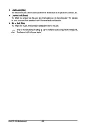
Microphones must be used to this jack. Mic In Jack (Pink) The default Mic in jack. GA-G31-S3G Motherboard - 20 - This jack can be connected to connect front speakers in a 4/5.1-channel audio configuration. Use this audio jack for a headphone or 2-channel speaker. Line In Jack (Blue) The default line in jack. Refer to the instructions on setting up a 2/4/5.1-channel audio configuration in devices such as an optical drive, walkman, etc. Use this audio jack for line in Chapter 5, "Configuring 2/4/5.1-Channel Audio." Line Out Jack (Green) The default line out jack.
Microphones must be used to this jack. Mic In Jack (Pink) The default Mic in jack. GA-G31-S3G Motherboard - 20 - This jack can be connected to connect front speakers in a 4/5.1-channel audio configuration. Use this audio jack for a headphone or 2-channel speaker. Line In Jack (Blue) The default line in jack. Refer to the instructions on setting up a 2/4/5.1-channel audio configuration in devices such as an optical drive, walkman, etc. Use this audio jack for line in Chapter 5, "Configuring 2/4/5.1-Channel Audio." Line Out Jack (Green) The default line out jack.
Manual
Page 22
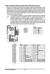
... 3.3V -12V GND PS_ON(soft On/Off) GND GND GND -5V +5V +5V +5V (Only for 2x12-pin ATX) GND (Only for 2x12-pin ATX) GA-G31-S3G Motherboard - 22 - Connect the power supply cable to the CPU. The 12V power connector mainly supplies power to the power connector in the correct orientation...
... 3.3V -12V GND PS_ON(soft On/Off) GND GND GND -5V +5V +5V +5V (Only for 2x12-pin ATX) GND (Only for 2x12-pin ATX) GA-G31-S3G Motherboard - 22 - Connect the power supply cable to the CPU. The 12V power connector mainly supplies power to the power connector in the correct orientation...
Manual
Page 24
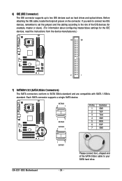
SATAII2 7 1 1 7 SATAII3 SATAII0 7 1 Pin No. 1 2 3 4 5 6 7 Definition GND TXP TXN GND RXN RXP GND GA-G31-S3G Motherboard 1 7 SATAII1 - 24 - Before attaching the IDE cable, locate the foolproof groove on the connector. Each SATA connector supports a single SATA device. If you wish ...
SATAII2 7 1 1 7 SATAII3 SATAII0 7 1 Pin No. 1 2 3 4 5 6 7 Definition GND TXP TXN GND RXN RXP GND GA-G31-S3G Motherboard 1 7 SATAII1 - 24 - Before attaching the IDE cable, locate the foolproof groove on the connector. Each SATA connector supports a single SATA device. If you wish ...
Manual
Page 26
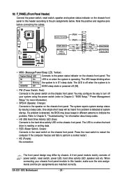
... Panel Header) Connect the power switch, reset switch, speaker and system status indicator on the chassis front panel. If a problem is in S1 sleep state. GA-G31-S3G Motherboard - 26 - The LED is off (S5). • PW (Power Switch, Red): Connects to the power switch on the chassis front panel to this header...
... Panel Header) Connect the power switch, reset switch, speaker and system status indicator on the chassis front panel. If a problem is in S1 sleep state. GA-G31-S3G Motherboard - 26 - The LED is off (S5). • PW (Power Switch, Red): Connects to the power switch on the chassis front panel to this header...
Manual
Page 28
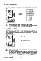
... information and BIOS configurations) and reset the CMOS values to USB 2.0/1.1 specification. Each USB header can provide two USB ports via an optional USB bracket. GA-G31-S3G Motherboard - 28 - To clear the CMOS values, place a jumper cap on your computer and unplug the power cord from the jumper. Open: Normal Short: Clear...
... information and BIOS configurations) and reset the CMOS values to USB 2.0/1.1 specification. Each USB header can provide two USB ports via an optional USB bracket. GA-G31-S3G Motherboard - 28 - To clear the CMOS values, place a jumper cap on your computer and unplug the power cord from the jumper. Open: Normal Short: Clear...
Manual
Page 32
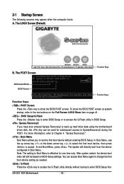
... or to access the Q-Flash utility directly without entering BIOS Setup. To exit Boot Menu, press . Motherboard Model BIOS Version Intel G31 BIOS for subsequent access to the instructions on the Full Screen LOGO Show item on BIOS Setup settings. 2-1 Startup Screen The following... screens may appear when the computer boots. The system will still be used for G31-S3G F1a . . . . : BIOS Setup/Q-Flash : XpressRecovery2 : Boot Menu : Qflash 02/03/2009-G31-ICH7-6A99OG0IC-00 Function Keys Function Keys: : POST Screen Press the key to show the BIOS POST...
... or to access the Q-Flash utility directly without entering BIOS Setup. To exit Boot Menu, press . Motherboard Model BIOS Version Intel G31 BIOS for subsequent access to the instructions on the Full Screen LOGO Show item on BIOS Setup settings. 2-1 Startup Screen The following... screens may appear when the computer boots. The system will still be used for G31-S3G F1a . . . . : BIOS Setup/Q-Flash : XpressRecovery2 : Boot Menu : Qflash 02/03/2009-G31-ICH7-6A99OG0IC-00 Function Keys Function Keys: : POST Screen Press the key to show the BIOS POST...
Manual
Page 34
... the previous settings remain in effect. First select the profile you wish to load, then press to complete. MB Intelligent Tweaker(M.I.T.) Use this task.) GA-G31-S3G Motherboard - 34 - An user password only allows you to view the BIOS settings but not to make changes in the BIOS Setup program to the...
... the previous settings remain in effect. First select the profile you wish to load, then press to complete. MB Intelligent Tweaker(M.I.T.) Use this task.) GA-G31-S3G Motherboard - 34 - An user password only allows you to view the BIOS settings but not to make changes in the BIOS Setup program to the...
Manual
Page 36
... CPU host clock. For a 1333 MHz FSB CPU, set the PCIe clock frequency. Auto sets memory multiplier according to manually set the system memory multiplier. GA-G31-S3G Motherboard - 36 - PCI Express Frequency (Mhz) Allows you to 0.7V at 0.1V increment. The adjustable range is automatically adjusted according to the CPU Host Frequency...
... CPU host clock. For a 1333 MHz FSB CPU, set the PCIe clock frequency. Auto sets memory multiplier according to manually set the system memory multiplier. GA-G31-S3G Motherboard - 36 - PCI Express Frequency (Mhz) Allows you to 0.7V at 0.1V increment. The adjustable range is automatically adjusted according to the CPU Host Frequency...
Manual
Page 38
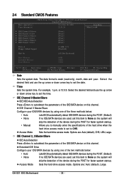
... during the POST. (Default) • None If no IDE/SATA devices are used , set this item to set the date. Options are : Auto (default), Large. GA-G31-S3G Motherboard - 38 - The date format is 13:0:0. Allows you to manually enter the specifications of the IDE/SATA device on this channel. Select the desired...
... during the POST. (Default) • None If no IDE/SATA devices are used , set this item to set the date. Options are : Auto (default), Large. GA-G31-S3G Motherboard - 38 - The date format is 13:0:0. Allows you to manually enter the specifications of the IDE/SATA device on this channel. Select the desired...
Manual
Page 40
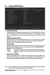
... supports this item, set the password(s) under the Set Supervisor/User Password item in the BIOS Main Menu. HDD S.M.A.R.T. This feature allows your hard drive. GA-G31-S3G Motherboard - 40 - 2-5 Advanced BIOS Features CMOS Setup Utility-Copyright (C) 1984-2009 Award Software Advanced BIOS Features Hard Disk Boot Priority First Boot Device Second...
... supports this item, set the password(s) under the Set Supervisor/User Password item in the BIOS Main Menu. HDD S.M.A.R.T. This feature allows your hard drive. GA-G31-S3G Motherboard - 40 - 2-5 Advanced BIOS Features CMOS Setup Utility-Copyright (C) 1984-2009 Award Software Advanced BIOS Features Hard Disk Boot Priority First Boot Device Second...

