Manual
Page 1
GA-G31-S3G LGA775 socket motherboard for Intel® CoreTM processor family/ Intel® Pentium® processor family/Intel® Celeron® processor family User's Manual Rev. 1001 12ME-G31S3G-1001R
GA-G31-S3G LGA775 socket motherboard for Intel® CoreTM processor family/ Intel® Pentium® processor family/Intel® Celeron® processor family User's Manual Rev. 1001 12ME-G31S3G-1001R

Manual
Page 2
Motherboard GA-G31-S3G Feb. 9, 2009 Motherboard GA-G31-S3G Feb. 9, 2009
Motherboard GA-G31-S3G Feb. 9, 2009 Motherboard GA-G31-S3G Feb. 9, 2009
Manual
Page 3
... may be reproduced, copied, translated, transmitted, or published in this manual are legally registered to use GIGABYTE's unique features, read or download the information on/from the Support\Motherboard\Technology Guide page on your motherboard revision before updating motherboard BIOS, drivers, or when looking for technical information. Example: No part of this manual may...
... may be reproduced, copied, translated, transmitted, or published in this manual are legally registered to use GIGABYTE's unique features, read or download the information on/from the Support\Motherboard\Technology Guide page on your motherboard revision before updating motherboard BIOS, drivers, or when looking for technical information. Example: No part of this manual may...
Manual
Page 4
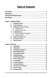
Table of Contents Box Contents ...6 OptionalItems ...6 GA-G31-S3G Motherboard Layout 7 Block Diagram ...8 Chapter 1 Hardware Installation 9 1-1 Installation Precautions 9 1-2 Product Specifications 10 1-3 Installing the CPU and CPU Cooler 13 1-3-1 Installing the CPU 13 1-3-2 Installing the CPU ...
Table of Contents Box Contents ...6 OptionalItems ...6 GA-G31-S3G Motherboard Layout 7 Block Diagram ...8 Chapter 1 Hardware Installation 9 1-1 Installation Precautions 9 1-2 Product Specifications 10 1-3 Installing the CPU and CPU Cooler 13 1-3-1 Installing the CPU 13 1-3-2 Installing the CPU ...
Manual
Page 6
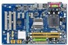
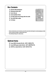
The box contents are for reference only. Optional Items 2-port USB 2.0 bracket (Part No. 12CR1-1UB030-5*R) 2-port SATA power cable (Part No. 12CF1-2SERPW-0*R) S/PDIF out cable (Part No. 12CR1-1SPOUT-0*R) - 6 - Box Contents GA-G31-S3G motherboard Motherboard driver disk User's Manual Quick Installation Guide One IDE cable and one floppy disk drive cable Two SATA 3Gb/s cables I/O Shield • The box contents above are subject to change without notice. • The motherboard image is for reference only and the actual items shall depend on product package you obtain.
The box contents are for reference only. Optional Items 2-port USB 2.0 bracket (Part No. 12CR1-1UB030-5*R) 2-port SATA power cable (Part No. 12CF1-2SERPW-0*R) S/PDIF out cable (Part No. 12CR1-1SPOUT-0*R) - 6 - Box Contents GA-G31-S3G motherboard Motherboard driver disk User's Manual Quick Installation Guide One IDE cable and one floppy disk drive cable Two SATA 3Gb/s cables I/O Shield • The box contents above are subject to change without notice. • The motherboard image is for reference only and the actual items shall depend on product package you obtain.
Manual
Page 7
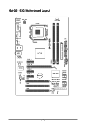
GA-G31-S3G Motherboard Layout KB_MS ATX_12V LGA775 CPU_FAN VGA COMA LPT USB R_USB LAN GA-G31-S3G ATX IDE AUDIO F_AUDIO RTL8111C IT8718 CODEC PCIE_1 PCIE_16 PCIE_2 PCIE_3 CD_IN SPDIF_O PCI1 PCI2 PCI3 Intel® G31 BATTERY Intel® ICH7 SATAII2 SATAII3 CLR_CMOS F_USB1 F_USB2 SATAII0 MBIOS FDD SYS_FAN CI SATAII1 DDRII1 DDRII2 PWR_LED F_PANEL - 7 -
GA-G31-S3G Motherboard Layout KB_MS ATX_12V LGA775 CPU_FAN VGA COMA LPT USB R_USB LAN GA-G31-S3G ATX IDE AUDIO F_AUDIO RTL8111C IT8718 CODEC PCIE_1 PCIE_16 PCIE_2 PCIE_3 CD_IN SPDIF_O PCI1 PCI2 PCI3 Intel® G31 BATTERY Intel® ICH7 SATAII2 SATAII3 CLR_CMOS F_USB1 F_USB2 SATAII0 MBIOS FDD SYS_FAN CI SATAII1 DDRII1 DDRII2 PWR_LED F_PANEL - 7 -
Manual
Page 9
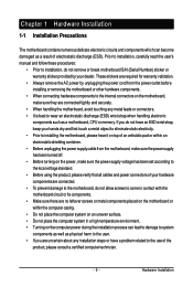
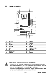
... shielding container. • Before unplugging the power supply cable from the power outlet before installing or removing the motherboard or other hardware components. • When connecting hardware components to the internal connectors on the computer power during the...damaged as a result of the product, please consult a certified computer technician. - 9 - Chapter 1 Hardware Installation 1-1 Installation Precautions The motherboard contains numerous delicate electronic circuits and components which can lead to damage to system components as well as physical harm to the user. •...
... shielding container. • Before unplugging the power supply cable from the power outlet before installing or removing the motherboard or other hardware components. • When connecting hardware components to the internal connectors on the computer power during the...damaged as a result of the product, please consult a certified computer technician. - 9 - Chapter 1 Hardware Installation 1-1 Installation Precautions The motherboard contains numerous delicate electronic circuits and components which can lead to damage to system components as well as physical harm to the user. •...
Manual
Page 10
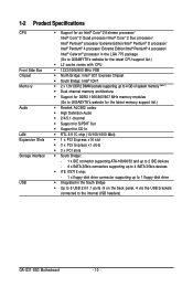
.../Intel® Pentium® 4 processor/ Intel® Celeron® processor in the LGA 775 package (Go to GIGABYTE's website for the latest CPU support list.) L2 cache varies with CPU 1333/1066/800 MHz FSB &#... (Note 1) Dual channel memory architecture Support for DDR2 1066/800/667 MHz memory modules (Go to GIGABYTE's website for the latest memory support list.) Realtek ALC662 codec High Definition Audio 2/4/5.1-channel &#... the back panel, 4 via the USB brackets connected to the internal USB headers) GA-G31-S3G Motherboard - 10 -
.../Intel® Pentium® 4 processor/ Intel® Celeron® processor in the LGA 775 package (Go to GIGABYTE's website for the latest CPU support list.) L2 cache varies with CPU 1333/1066/800 MHz FSB &#... (Note 1) Dual channel memory architecture Support for DDR2 1066/800/667 MHz memory modules (Go to GIGABYTE's website for the latest memory support list.) Realtek ALC662 codec High Definition Audio 2/4/5.1-channel &#... the back panel, 4 via the USB brackets connected to the internal USB headers) GA-G31-S3G Motherboard - 10 -
Manual
Page 12
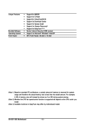
GA-G31-S3G Motherboard - 12 - Unique Features Bundled Software Operating System Form Factor Support for @BIOS Support for Q-Flash Support for Virtual Dual BIOS Support .../XP ATX Form Factor; 30.5cm x 19.4cm (Note 1) Based on the CPU cooler you install. (Note 3) Available functions in EasyTune may differ by motherboard model. For example, 4 GB of memory size will instead be shown as 3.xx GB during system startup. (Note 2) Whether the CPU fan speed control function...
GA-G31-S3G Motherboard - 12 - Unique Features Bundled Software Operating System Form Factor Support for @BIOS Support for Q-Flash Support for Virtual Dual BIOS Support .../XP ATX Form Factor; 30.5cm x 19.4cm (Note 1) Based on the CPU cooler you install. (Note 3) Available functions in EasyTune may differ by motherboard model. For example, 4 GB of memory size will instead be shown as 3.xx GB during system startup. (Note 2) Whether the CPU fan speed control function...
Manual
Page 13
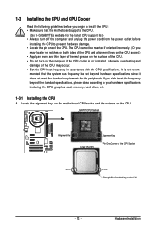
... of the CPU. • Do not turn on the computer if the CPU cooler is not recom- Hardware Installation Locate the alignment keys on the motherboard CPU socket and the notches on the CPU - 13 - It is not installed, otherwise overheating and damage of the CPU may locate the notches on... layer of thermal grease on the surface of the CPU Socket Notch Notch Triangle Pin One Marking on the CPU. mended that the motherboard supports the CPU. (Go to GIGABYTE's website for the latest CPU support list.) • Always turn off the computer and unplug the power cord from the power outlet...
... of the CPU. • Do not turn on the computer if the CPU cooler is not recom- Hardware Installation Locate the alignment keys on the motherboard CPU socket and the notches on the CPU - 13 - It is not installed, otherwise overheating and damage of the CPU may locate the notches on... layer of thermal grease on the surface of the CPU Socket Notch Notch Triangle Pin One Marking on the CPU. mended that the motherboard supports the CPU. (Go to GIGABYTE's website for the latest CPU support list.) • Always turn off the computer and unplug the power cord from the power outlet...
Manual
Page 14
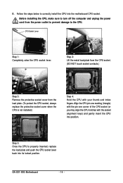
... 5: Once the CPU is not installed.) Step 4: Hold the CPU with the socket alignment keys) and gently insert the CPU into its locked position. GA-G31-S3G Motherboard - 14 - CPU Socket Lever Step 1: Completely raise the CPU socket lever. Step 2: Lift the metal load plate from the CPU socket. (DO NOT... touch socket contacts.) Step 3: Remove the protective socket cover from the power outlet to prevent damage to correctly install the CPU into the motherboard CPU socket. Align the CPU pin one marking (triangle) with the pin one corner of the CPU socket (or you may align the CPU...
... 5: Once the CPU is not installed.) Step 4: Hold the CPU with the socket alignment keys) and gently insert the CPU into its locked position. GA-G31-S3G Motherboard - 14 - CPU Socket Lever Step 1: Completely raise the CPU socket lever. Step 2: Lift the metal load plate from the CPU socket. (DO NOT... touch socket contacts.) Step 3: Remove the protective socket cover from the power outlet to prevent damage to correctly install the CPU into the motherboard CPU socket. Align the CPU pin one marking (triangle) with the pin one corner of the CPU socket (or you may align the CPU...
Manual
Page 15
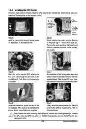
... CPU cooler may adhere to install.) Step 3: Place the cooler atop the CPU, aligning the four push pins through the pin holes on the motherboard. Hardware Installation Push down each push pin. Check that the Male and Female push pins are joined closely. (Refer to your CPU cooler installation ... cooler, on the contrary, is to the CPU. 1-3-2 Installing the CPU Cooler Follow the steps below to correctly install the CPU cooler on the motherboard. (The following procedure uses Intel® boxed cooler as the picture above, the installation is complete. Direction of the Arrow Sign on the Male ...
... CPU cooler may adhere to install.) Step 3: Place the cooler atop the CPU, aligning the four push pins through the pin holes on the motherboard. Hardware Installation Push down each push pin. Check that the Male and Female push pins are joined closely. (Refer to your CPU cooler installation ... cooler, on the contrary, is to the CPU. 1-3-2 Installing the CPU Cooler Follow the steps below to correctly install the CPU cooler on the motherboard. (The following procedure uses Intel® boxed cooler as the picture above, the installation is complete. Direction of the Arrow Sign on the Male ...
Manual
Page 16
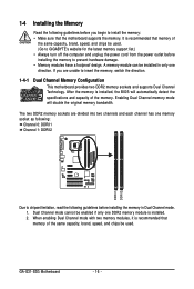
...mode. 1. Enabling Dual Channel memory mode will automatically detect the specifications and capacity of the same capacity, brand, speed, and chips be used . GA-G31-S3G Motherboard - 16 - Dual Channel mode cannot be enabled if only one direction. It is installed, the BIOS will double the original memory bandwidth. 1-4...in only one DDR2 memory module is recommended that memory of the same capacity, brand, speed, and chips be used . (Go to GIGABYTE's website for the latest memory support list.) • Always turn off the computer and unplug the power cord from the power outlet before...
...mode. 1. Enabling Dual Channel memory mode will automatically detect the specifications and capacity of the same capacity, brand, speed, and chips be used . GA-G31-S3G Motherboard - 16 - Dual Channel mode cannot be enabled if only one direction. It is installed, the BIOS will double the original memory bandwidth. 1-4...in only one DDR2 memory module is recommended that memory of the same capacity, brand, speed, and chips be used . (Go to GIGABYTE's website for the latest memory support list.) • Always turn off the computer and unplug the power cord from the power outlet before...
Manual
Page 17
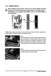
... in one direction. As indicated in the memory sockets. Hardware Installation Follow the steps below to the memory module. Place the memory module on this motherboard. Spread the retaining clips at both ends of the memory module. Notch DDR2 DIMM A DDR2 memory module has a notch, so it vertically into place when...
... in one direction. As indicated in the memory sockets. Hardware Installation Follow the steps below to the memory module. Place the memory module on this motherboard. Spread the retaining clips at both ends of the memory module. Notch DDR2 DIMM A DDR2 memory module has a notch, so it vertically into place when...
Manual
Page 18
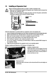
...the top edge of the card until it is securely seated in the expansion slot. 1. Install the driver provided with your expansion card(s). 7. GA-G31-S3G Motherboard - 18 - PCI Express x1 Slot PCI Express x16 Slot PCI Slot Follow the steps below to make any required BIOS changes for your ...off the computer and unplug the power cord from the power outlet before you begin to install an expansion card: • Make sure the motherboard supports the expansion card. If necessary, go to BIOS Setup to correctly install your computer. 1-5 Installing an Expansion Card Read the following ...
...the top edge of the card until it is securely seated in the expansion slot. 1. Install the driver provided with your expansion card(s). 7. GA-G31-S3G Motherboard - 18 - PCI Express x1 Slot PCI Express x16 Slot PCI Slot Follow the steps below to make any required BIOS changes for your ...off the computer and unplug the power cord from the power outlet before you begin to install an expansion card: • Make sure the motherboard supports the expansion card. If necessary, go to BIOS Setup to correctly install your computer. 1-5 Installing an Expansion Card Read the following ...
Manual
Page 19
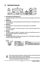
... a PS/2 mouse and the lower port (purple) to prevent an electrical short inside the cable connector. - 19 - Do not rock it straight out from the motherboard. • When removing the cable, pull it side to side to connect a PS/2 keyboard. Parallel Port Use the parallel port to connect devices such as...
... a PS/2 mouse and the lower port (purple) to prevent an electrical short inside the cable connector. - 19 - Do not rock it straight out from the motherboard. • When removing the cable, pull it side to side to connect a PS/2 keyboard. Parallel Port Use the parallel port to connect devices such as...
Manual
Page 20
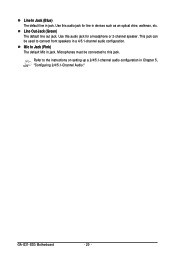
Line Out Jack (Green) The default line out jack. GA-G31-S3G Motherboard - 20 - Use this audio jack for line in a 4/5.1-channel audio configuration. This jack can be connected to this audio jack for a headphone or 2-channel speaker. Mic In Jack (Pink) The default Mic in jack. Line In Jack (Blue) The default line in jack. Use this jack. Refer to connect front speakers in devices such as an optical drive, walkman, etc. Microphones must be used to the instructions on setting up a 2/4/5.1-channel audio configuration in Chapter 5, "Configuring 2/4/5.1-Channel Audio."
Line Out Jack (Green) The default line out jack. GA-G31-S3G Motherboard - 20 - Use this audio jack for line in a 4/5.1-channel audio configuration. This jack can be connected to this audio jack for a headphone or 2-channel speaker. Mic In Jack (Pink) The default Mic in jack. Line In Jack (Blue) The default line in jack. Use this jack. Refer to connect front speakers in devices such as an optical drive, walkman, etc. Microphones must be used to the instructions on setting up a 2/4/5.1-channel audio configuration in Chapter 5, "Configuring 2/4/5.1-Channel Audio."
Manual
Page 21
..., make sure your devices are compliant with the connectors you wish to connect. • Before installing the devices, be sure to the connector on the motherboard. - 21 - Unplug the power cord from the power outlet to prevent damage to the devices. • After installing the device and before connecting external devices...
..., make sure your devices are compliant with the connectors you wish to connect. • Before installing the devices, be sure to the connector on the motherboard. - 21 - Unplug the power cord from the power outlet to prevent damage to the devices. • After installing the device and before connecting external devices...
Manual
Page 22
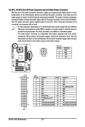
...cover when using a 2x12 power supply, remove the protective cover from the main power connector on the motherboard. 1/2) ATX_12V/ATX (2x2 12V Power Connector and 2x12 Main Power Connector) With the use of the...compatible with power supplies with 2x10 power connectors. If a power supply is turned off and all the components on the motherboard. Before connecting the power connector, first make sure the power supply is used (500W or greater). When using a... (Only for 2x12-pin ATX) GND (Only for 2x12-pin ATX) GA-G31-S3G Motherboard - 22 - Connect the power supply cable to the CPU.
...cover when using a 2x12 power supply, remove the protective cover from the main power connector on the motherboard. 1/2) ATX_12V/ATX (2x2 12V Power Connector and 2x12 Main Power Connector) With the use of the...compatible with power supplies with 2x10 power connectors. If a power supply is turned off and all the components on the motherboard. Before connecting the power connector, first make sure the power supply is used (500W or greater). When using a... (Only for 2x12-pin ATX) GND (Only for 2x12-pin ATX) GA-G31-S3G Motherboard - 22 - Connect the power supply cable to the CPU.
Manual
Page 23
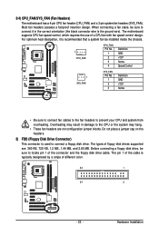
... be sure to the CPU or the system may result in the correct orientation (the black connector wire is the ground wire). Hardware Installation The motherboard supports CPU fan speed control, which requires the use of floppy disk drives supported are not configuration jumper blocks. Overheating may hang. • These...floppy disk drive. Most fan headers possess a foolproof insertion design. The types of a CPU fan with fan speed control design. 3/4) CPU_FAN/SYS_FAN (Fan Headers) The motherboard has a 4-pin CPU fan header (CPU_FAN) and a 3-pin system fan headers (SYS_FAN).
... be sure to the CPU or the system may result in the correct orientation (the black connector wire is the ground wire). Hardware Installation The motherboard supports CPU fan speed control, which requires the use of floppy disk drives supported are not configuration jumper blocks. Overheating may hang. • These...floppy disk drive. Most fan headers possess a foolproof insertion design. The types of a CPU fan with fan speed control design. 3/4) CPU_FAN/SYS_FAN (Fan Headers) The motherboard has a 4-pin CPU fan header (CPU_FAN) and a 3-pin system fan headers (SYS_FAN).


