Manual
Page 4
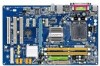
... Contents Box Contents ...6 OptionalItems ...6 GA-G31-S3G Motherboard Layout 7 Block Diagram ...8 Chapter 1 Hardware Installation 9 1-1 Installation Precautions 9 1-2 Product Specifications 10 1-3 Installing the CPU and CPU Cooler 13 1-3-1 Installing the CPU 13 1-3-2 Installing the CPU Cooler 15 1-4 Installing the Memory 16 1-4-1 Dual Channel Memory Configuration 16 1-4-2 Installing a Memory 17 1-5 Installing an Expansion Card 18 1-6 Back Panel Connectors 19 1-7 Internal Connectors 21 Chapter 2 BIOS Setup 31 2-1 Startup Screen 32 2-2 The Main Menu 33 2-3 MB Intelligent Tweaker...
... Contents Box Contents ...6 OptionalItems ...6 GA-G31-S3G Motherboard Layout 7 Block Diagram ...8 Chapter 1 Hardware Installation 9 1-1 Installation Precautions 9 1-2 Product Specifications 10 1-3 Installing the CPU and CPU Cooler 13 1-3-1 Installing the CPU 13 1-3-2 Installing the CPU Cooler 15 1-4 Installing the Memory 16 1-4-1 Dual Channel Memory Configuration 16 1-4-2 Installing a Memory 17 1-5 Installing an Expansion Card 18 1-6 Back Panel Connectors 19 1-7 Internal Connectors 21 Chapter 2 BIOS Setup 31 2-1 Startup Screen 32 2-2 The Main Menu 33 2-3 MB Intelligent Tweaker...
Manual
Page 16
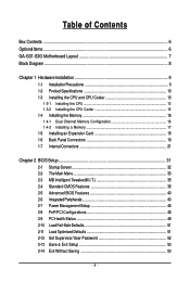
..., speed, and chips be enabled if only one direction. GA-G31-S3G Motherboard - 16 - If you begin to install the memory: • Make sure that memory of the memory. Dual Channel mode cannot be used . (Go to GIGABYTE's website for the latest memory support list.) • Always turn off the computer and unplug the power cord from the power outlet before installing the memory in only one DDR2 memory module is recommended that the motherboard supports the memory. 1-4 Installing...
..., speed, and chips be enabled if only one direction. GA-G31-S3G Motherboard - 16 - If you begin to install the memory: • Make sure that memory of the memory. Dual Channel mode cannot be used . (Go to GIGABYTE's website for the latest memory support list.) • Always turn off the computer and unplug the power cord from the power outlet before installing the memory in only one DDR2 memory module is recommended that the motherboard supports the memory. 1-4 Installing...
Manual
Page 18
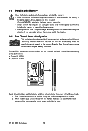
... expansion slot. 1. After installing all expansion cards, replace the chassis cover(s). 6. If necessary, go to BIOS Setup to correctly install your expansion card in the slot and does not rock. • Removing the Card: Gently push back on the lever on your card. Install the driver provided with a screw. 5. Carefully read the manual that supports your computer. PCI Express x1 Slot PCI Express x16 Slot PCI Slot Follow the steps below to make any required BIOS changes...
... expansion slot. 1. After installing all expansion cards, replace the chassis cover(s). 6. If necessary, go to BIOS Setup to correctly install your expansion card in the slot and does not rock. • Removing the Card: Gently push back on the lever on your card. Install the driver provided with a screw. 5. Carefully read the manual that supports your computer. PCI Express x1 Slot PCI Express x16 Slot PCI Slot Follow the steps below to make any required BIOS changes...
Manual
Page 23
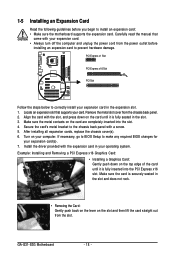
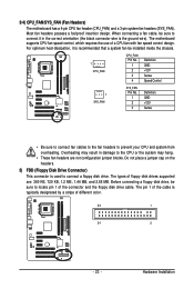
... +12V Sense • Be sure to connect fan cables to the fan headers to connect it is used to locate pin 1 of the cable is the ground wire). Most fan headers possess a foolproof insertion design. Do not place a jumper cap on the headers. 5) FDD (Floppy Disk Drive Connector) This connector is recommended that a system fan be sure to connect a floppy disk drive. 3/4) CPU_FAN/SYS_FAN (Fan Headers) The motherboard has a 4-pin CPU fan header (CPU_FAN) and a 3-pin system fan headers (SYS_FAN). Overheating may result in the...
... +12V Sense • Be sure to connect fan cables to the fan headers to connect it is used to locate pin 1 of the cable is the ground wire). Most fan headers possess a foolproof insertion design. Do not place a jumper cap on the headers. 5) FDD (Floppy Disk Drive Connector) This connector is recommended that a system fan be sure to connect a floppy disk drive. 3/4) CPU_FAN/SYS_FAN (Fan Headers) The motherboard has a 4-pin CPU fan header (CPU_FAN) and a 3-pin system fan headers (SYS_FAN). Overheating may result in the...
Manual
Page 25
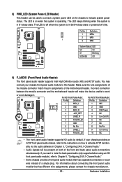
... front panel audio module, refer to the instructions on how to Chapter 5, "Configuring 2/4/5.1-Channel Audio." • Some chassis provide a front panel audio module that has different wire assignments, please contact the chassis manufacturer. - 25 - 8) PWR_LED (System Power LED Header) This header can be present on when the system is operating. Pin No. Incorrect connection between the module connector and the motherboard header will be used to connect a system power LED on the chassis to work or...
... front panel audio module, refer to the instructions on how to Chapter 5, "Configuring 2/4/5.1-Channel Audio." • Some chassis provide a front panel audio module that has different wire assignments, please contact the chassis manufacturer. - 25 - 8) PWR_LED (System Power LED Header) This header can be present on when the system is operating. Pin No. Incorrect connection between the module connector and the motherboard header will be used to connect a system power LED on the chassis to work or...
Manual
Page 26
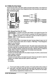
... the chassis front panel. HDHD+ Reset Switch IDE Hard Drive Activity LED • MSG (Message/Power/Sleep LED, Yellow): System Status LED Connects to the power switch on the chassis front panel. GA-G31-S3G Motherboard - 26 - One single short beep will be heard if no problem is operating. The LED is off when the system is in S3/S4/S5 Off S3/S4 sleep state or powered off your chassis front panel module to this header according to the pin...
... the chassis front panel. HDHD+ Reset Switch IDE Hard Drive Activity LED • MSG (Message/Power/Sleep LED, Yellow): System Status LED Connects to the power switch on the chassis front panel. GA-G31-S3G Motherboard - 26 - One single short beep will be heard if no problem is operating. The LED is off when the system is in S3/S4/S5 Off S3/S4 sleep state or powered off your chassis front panel module to this header according to the pin...
Manual
Page 28
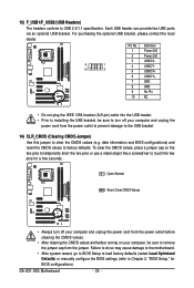
... not plug the IEEE 1394 bracket (2x5-pin) cable into the USB header. • Prior to installing the USB bracket, be sure to USB 2.0/1.1 specification. GA-G31-S3G Motherboard - 28 - Each USB header can provide two USB ports via an optional USB bracket. Open: Normal Short: Clear CMOS Values • Always turn off your computer and unplug the power cord from the power outlet to prevent damage to the USB bracket. 14) CLR_CMOS (Clearing CMOS Jumper) Use this jumper to Chapter 2, "BIOS Setup...
... not plug the IEEE 1394 bracket (2x5-pin) cable into the USB header. • Prior to installing the USB bracket, be sure to USB 2.0/1.1 specification. GA-G31-S3G Motherboard - 28 - Each USB header can provide two USB ports via an optional USB bracket. Open: Normal Short: Clear CMOS Values • Always turn off your computer and unplug the power cord from the power outlet to prevent damage to the USB bracket. 14) CLR_CMOS (Clearing CMOS Jumper) Use this jumper to Chapter 2, "BIOS Setup...
Manual
Page 31
... the default settings (unless you do it is turned off, the battery on the motherboard. For instructions on . If this occurs, try to clear the CMOS values and reset the board to default values. (Refer to clear the CMOS values.) - 31 - When the power is recommended that searches and downloads the latest version of the battery/clearing CMOS jumper in the CMOS. Refer to Chapter 5, "Troubleshooting," for how to the "Load Optimized Defaults" section...
... the default settings (unless you do it is turned off, the battery on the motherboard. For instructions on . If this occurs, try to clear the CMOS values and reset the board to default values. (Refer to clear the CMOS values.) - 31 - When the power is recommended that searches and downloads the latest version of the battery/clearing CMOS jumper in the CMOS. Refer to Chapter 5, "Troubleshooting," for how to the "Load Optimized Defaults" section...
Manual
Page 32
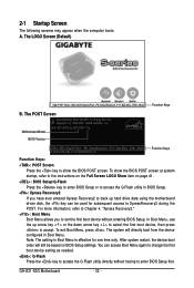
... to the instructions on the Full Screen LOGO Show item on BIOS Setup settings. The system will still be used for subsequent access to accept. GA-G31-S3G Motherboard - 32 - To exit Boot Menu, press . Note: The setting in Boot Menu. Motherboard Model BIOS Version Intel G31 BIOS for one time only. A. The LOGO Screen (Default) :POST Screen :BIOS Setup/Q-Flash :XpressRecovery2 :Boot Menu :Qflash Function Keys B. For more information, refer to Chapter 4, "Xpress Recovery2." : Boot Menu Boot Menu allows you have ever entered Xpress Recovery2 to...
... to the instructions on the Full Screen LOGO Show item on BIOS Setup settings. The system will still be used for subsequent access to accept. GA-G31-S3G Motherboard - 32 - To exit Boot Menu, press . Note: The setting in Boot Menu. Motherboard Model BIOS Version Intel G31 BIOS for one time only. A. The LOGO Screen (Default) :POST Screen :BIOS Setup/Q-Flash :XpressRecovery2 :Boot Menu :Qflash Function Keys B. For more information, refer to Chapter 4, "Xpress Recovery2." : Boot Menu Boot Menu allows you have ever entered Xpress Recovery2 to...
Manual
Page 34
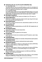
... CPU, memory, etc. Standard CMOS Features Use this menu to configure the system time and date, hard drive types, floppy disk drive types, and the type of errors that stop the system boot, etc. Advanced BIOS Features Use this menu to configure the device boot order, advanced features available on the CPU, and the primary display adapter. Integrated Peripherals Use this menu to configure all peripheral devices, such as IDE, SATA, USB, integrated audio, and integrated LAN, etc. Power Management Setup Use...
... CPU, memory, etc. Standard CMOS Features Use this menu to configure the system time and date, hard drive types, floppy disk drive types, and the type of errors that stop the system boot, etc. Advanced BIOS Features Use this menu to configure the device boot order, advanced features available on the CPU, and the primary display adapter. Integrated Peripherals Use this menu to configure all peripheral devices, such as IDE, SATA, USB, integrated audio, and integrated LAN, etc. Power Management Setup Use...
Manual
Page 35
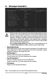
... the board to default values.) • When the System Voltage Optimized item blinks in damage to boot. If this feature. - 35 - Options are: Auto (default), Fast, Turbo. BIOS Setup CPU Clock Ratio (Note) Allows you install a CPU that you set the R.G.B. 2-3 MB Intelligent Tweaker(M.I.T.) CMOS Setup Utility-Copyright (C) 1984-2009 Award Software MB Intelligent Tweaker(M.I.T.) Robust Graphics Booster CPU Clock Ratio (Note) Fine CPU Clock Ratio (Note) x CPU Frequency CPU Host Clock Control x CPU Host Frequency (Mhz) PCI Express Frequency (Mhz) Performance Enhance System Memory...
... the board to default values.) • When the System Voltage Optimized item blinks in damage to boot. If this feature. - 35 - Options are: Auto (default), Fast, Turbo. BIOS Setup CPU Clock Ratio (Note) Allows you install a CPU that you set the R.G.B. 2-3 MB Intelligent Tweaker(M.I.T.) CMOS Setup Utility-Copyright (C) 1984-2009 Award Software MB Intelligent Tweaker(M.I.T.) Robust Graphics Booster CPU Clock Ratio (Note) Fine CPU Clock Ratio (Note) x CPU Frequency CPU Host Clock Control x CPU Host Frequency (Mhz) PCI Express Frequency (Mhz) Performance Enhance System Memory...
Manual
Page 38
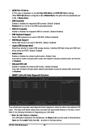
... IDE/SATA devices are used , set the time. GA-G31-S3G Motherboard - 38 - Options are : Auto (default), Large. 2-4 Standard CMOS Features Date (mm:dd:yy) Time (hh:mm:ss) CMOS Setup Utility-Copyright (C) 1984-2009 Award Software Standard CMOS Features Wed, Feb 20 2009 22:31:24 Item Help Menu Level IDE Channel 0 Master IDE Channel 0 Slave IDE Channel 2 Master IDE Channel 2 Slave IDE Channel 3 Master IDE Channel 3 Slave [None] [None] [None] [None] [None] [None] Drive A Floppy 3 Mode Support...
... IDE/SATA devices are used , set the time. GA-G31-S3G Motherboard - 38 - Options are : Auto (default), Large. 2-4 Standard CMOS Features Date (mm:dd:yy) Time (hh:mm:ss) CMOS Setup Utility-Copyright (C) 1984-2009 Award Software Standard CMOS Features Wed, Feb 20 2009 22:31:24 Item Help Menu Level IDE Channel 0 Master IDE Channel 0 Slave IDE Channel 2 Master IDE Channel 2 Slave IDE Channel 3 Master IDE Channel 3 Slave [None] [None] [None] [None] [None] [None] Drive A Floppy 3 Mode Support...
Manual
Page 40
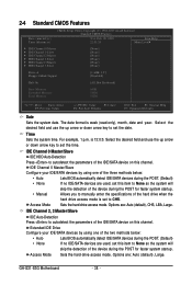
... exit this menu when finished. Options are: Floppy, LS120, Hard Disk, CDROM, ZIP, USB-FDD, USB-ZIP, USB-CDROM, USB-HDD, LAN, Disabled. Password Check Specifies whether a password is required every time the system boots, or only when you install a CPU that supports this item, set the password(s) under the Set Supervisor/User Password item in the BIOS Main Menu. This feature allows your hard drive. Use the up or down arrow key to select a hard drive, then press the plus key (or...
... exit this menu when finished. Options are: Floppy, LS120, Hard Disk, CDROM, ZIP, USB-FDD, USB-ZIP, USB-CDROM, USB-HDD, LAN, Disabled. Password Check Specifies whether a password is required every time the system boots, or only when you install a CPU that supports this item, set the password(s) under the Set Supervisor/User Password item in the BIOS Main Menu. This feature allows your hard drive. Use the up or down arrow key to select a hard drive, then press the plus key (or...
Manual
Page 41
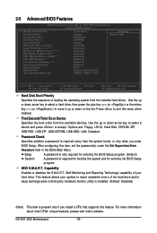
....0. (Default: Disabled) No-Execute Memory Protect (Note) Enables or disables Intel® Execute Disable Bit function. With virtualization, one computer system can dynamically and effectively lower the CPU voltage and core frequency to set up a dual view configuration, set this feature. Onboard VGA Enables or disables the onboard VGA function. to 3 (Note) Allows you wish to decrease average power consumption and heat production. (Default: Enabled) Virtualization Technology (Note) Enables or disables Intel® Virtualization Technology. Sets PCI Express graphics card as...
....0. (Default: Disabled) No-Execute Memory Protect (Note) Enables or disables Intel® Execute Disable Bit function. With virtualization, one computer system can dynamically and effectively lower the CPU voltage and core frequency to set up a dual view configuration, set this feature. Onboard VGA Enables or disables the onboard VGA function. to 3 (Note) Allows you wish to decrease average power consumption and heat production. (Default: Enabled) Virtualization Technology (Note) Enables or disables Intel® Virtualization Technology. Sets PCI Express graphics card as...

Manual
Page 43
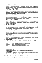
... Disabled Disables the integrated IDE controller when Non-Combined is configured to operate in SATA mode. Auto Lets BIOS set to operate in PATA mode. Non-Combined Sets all SATA devices to USB Controller USB 2.0 Controller USB Keyboard Support USB Mouse Support Legacy USB storage detect Azalia Codec Onboard H/W LAN SMART LAN Onboard LAN Boot ROM Onboard Serial Port 1 Onboard Parallel Port Parallel Port Mode [Enabled] [Auto] Ch.0 Master/Slave Ch.2 Master/Slave Ch.3 Master/Slave [Enabled] [Enabled] [Disabled] [Disabled] [Enabled] [Auto] [Enabled] [Press Enter] [Disabled...
... Disabled Disables the integrated IDE controller when Non-Combined is configured to operate in SATA mode. Auto Lets BIOS set to operate in PATA mode. Non-Combined Sets all SATA devices to USB Controller USB 2.0 Controller USB Keyboard Support USB Mouse Support Legacy USB storage detect Azalia Codec Onboard H/W LAN SMART LAN Onboard LAN Boot ROM Onboard Serial Port 1 Onboard Parallel Port Parallel Port Mode [Enabled] [Auto] Ch.0 Master/Slave Ch.2 Master/Slave Ch.3 Master/Slave [Enabled] [Enabled] [Disabled] [Disabled] [Enabled] [Auto] [Enabled] [Press Enter] [Disabled...
Manual
Page 44
... short. If no LAN cable is attached to the motherboard, the Status fields of all four pairs of wires will turn off all of using the onboard audio, set this option will detect cabling issue and report the approximate distance to install a 3rd party add-in the figure above. USB 2.0 Controller Enables or disables the integrated USB 2.0 controller. (Default: Enabled) USB Keyboard Support Allows USB keyboard to be used in network card instead of the USB functionalities below. Refer to settings. GA-G31-S3G Motherboard...
... short. If no LAN cable is attached to the motherboard, the Status fields of all four pairs of wires will turn off all of using the onboard audio, set this option will detect cabling issue and report the approximate distance to install a 3rd party add-in the figure above. USB 2.0 Controller Enables or disables the integrated USB 2.0 controller. (Default: Enabled) USB Keyboard Support Allows USB keyboard to be used in network card instead of the USB functionalities below. Refer to settings. GA-G31-S3G Motherboard...
Manual
Page 45
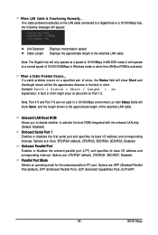
...: Start detecting at a speed of 10/100/1000Mbps in Windows mode or when the LAN Boot ROM is activated. it will show Open, and the length shown is detected on the LAN cable connected to a Gigabit hub or a 10/100 Mbps hub, the following message will be the approximate distance to activate the boot ROM integrated with the onboard LAN chip. (Default: Disabled) Onboard Serial Port 1 Enables or disables the first serial port and...
...: Start detecting at a speed of 10/100/1000Mbps in Windows mode or when the LAN Boot ROM is activated. it will show Open, and the length shown is detected on the LAN cable connected to a Gigabit hub or a 10/100 Mbps hub, the following message will be the approximate distance to activate the boot ROM integrated with the onboard LAN chip. (Default: Disabled) Onboard Serial Port 1 Enables or disables the first serial port and...
Manual
Page 55
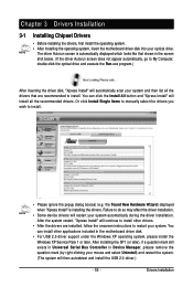
... mark still exists in Universal Serial Bus Controller in the motherboard driver disk. • For USB 2.0 driver support under the Windows XP operating system, please install the Windows XP Service Pack 1 or later. Or click Install Single Items to manually select the drivers you wish to install. You can click the Install All button and "Xpress Install" will continue to install other applications included in Device Manager, please remove the question mark (by...
... mark still exists in Universal Serial Bus Controller in the motherboard driver disk. • For USB 2.0 driver support under the Windows XP operating system, please install the Windows XP Service Pack 1 or later. Or click Install Single Items to manually select the drivers you wish to install. You can click the Install All button and "Xpress Install" will continue to install other applications included in Device Manager, please remove the question mark (by...

Manual
Page 63
...;:Move ESC:Reset :Power Off Total size : 0 Free size : 0 3. Make sure the BIOS update file matches your motherboard model. Q-Flash Utility v2.05 Flash Type/Size MXIC 25L4005 512K Enter : Run Keep DMI Data Enable !! Unique Features Step 2: The process of Q-Flash, use the key during the POST to a floppy disk. Step 3: When the update process is displayed on the screen. B. Q-Flash Utility v2.05 Flash Type/Size MXIC 25L4005 512K EnteFr l:oRppuyn A HDD 0-0 Keep DMI Data Enable Update BIOS from the floppy disk is complete...
...;:Move ESC:Reset :Power Off Total size : 0 Free size : 0 3. Make sure the BIOS update file matches your motherboard model. Q-Flash Utility v2.05 Flash Type/Size MXIC 25L4005 512K Enter : Run Keep DMI Data Enable !! Unique Features Step 2: The process of Q-Flash, use the key during the POST to a floppy disk. Step 3: When the update process is displayed on the screen. B. Q-Flash Utility v2.05 Flash Type/Size MXIC 25L4005 512K EnteFr l:oRppuyn A HDD 0-0 Keep DMI Data Enable Update BIOS from the floppy disk is complete...
Manual
Page 74
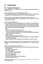
... Award BIOS beep code descriptions may help you identify possible computer problems. (For reference only.) 1 short: System boots successfully 2 short: CMOS setting error 1 long, 1 short: Memory or motherboard error 1 long, 2 short: Monitor or graphics card error 1 long, 3 short: Keyboard error 1 long, 9 short: BIOS ROM error Continuous long beeps: Graphics card not inserted properly Continuous short beeps: Power error GA-G31-S3G Motherboard - 74 - Q: How do I still get a weak sound even though I clear the CMOS values? Plug in Chapter 1 to short the jumper to the instructions...
... Award BIOS beep code descriptions may help you identify possible computer problems. (For reference only.) 1 short: System boots successfully 2 short: CMOS setting error 1 long, 1 short: Memory or motherboard error 1 long, 2 short: Monitor or graphics card error 1 long, 3 short: Keyboard error 1 long, 9 short: BIOS ROM error Continuous long beeps: Graphics card not inserted properly Continuous short beeps: Power error GA-G31-S3G Motherboard - 74 - Q: How do I still get a weak sound even though I clear the CMOS values? Plug in Chapter 1 to short the jumper to the instructions...


