Manual
Page 4
...Heatsink from the Back of the Motherboard ..... 16 1-4 Installing the Memory 17 1-4-1 Dual Channel Memory Configuration 17 1-4-2 Installing a Memory 18 1-5 Installing an Expansion Card 19 1-6 Installing the SATA Bracket 20 1-7 Back Panel Connectors 21 1-8 Internal Connectors 23 Chapter 2 BIOS Setup 37 2-1 Startup Screen 38 2-2 The Main Menu 39 2-3 Standard CMOS Features 41 2-4 Advanced BIOS Features 43 2-5 IntegratedPeripherals 45 2-6 Power Management Setup 49 2-7 PnP/PCI Configurations 51 2-8 PC Health Status 52 2-9 MB Intelligent Tweaker(M.I.T 54 2-10 Load Fail-Safe Defaults...
...Heatsink from the Back of the Motherboard ..... 16 1-4 Installing the Memory 17 1-4-1 Dual Channel Memory Configuration 17 1-4-2 Installing a Memory 18 1-5 Installing an Expansion Card 19 1-6 Installing the SATA Bracket 20 1-7 Back Panel Connectors 21 1-8 Internal Connectors 23 Chapter 2 BIOS Setup 37 2-1 Startup Screen 38 2-2 The Main Menu 39 2-3 Standard CMOS Features 41 2-4 Advanced BIOS Features 43 2-5 IntegratedPeripherals 45 2-6 Power Management Setup 49 2-7 PnP/PCI Configurations 51 2-8 PC Health Status 52 2-9 MB Intelligent Tweaker(M.I.T 54 2-10 Load Fail-Safe Defaults...

Manual
Page 10
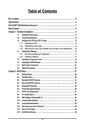
... technology (The PCI Express x16 slots conform to PCI Express 2.0 standard.) Š 3 x PCI Express x1 slots Š 2 x PCI slots Š South Bridge: - 6 x SATA 3Gb/s connectors (SATAII0, SATAII1, SATAII2, SATAII3, SATAII4, SATAII5) supporting up to the internal IEEE 1394a header) GA-EX38T-DQ6 Motherboard - 10 - Support for SATA RAID 0, RAID 1, RAID 5, and RAID 10 Š GIGABYTE SATA2 chip: - 1 x IDE connector supporting ATA-133/100/66/33 and up to 2 IDE devices - 2 x SATA 3Gb/s connectors (GSATAIIA, GSATAIIB) supporting up to 2 SATA 3Gb/s devices - Support for SATA RAID 0, RAID...
... technology (The PCI Express x16 slots conform to PCI Express 2.0 standard.) Š 3 x PCI Express x1 slots Š 2 x PCI slots Š South Bridge: - 6 x SATA 3Gb/s connectors (SATAII0, SATAII1, SATAII2, SATAII3, SATAII4, SATAII5) supporting up to the internal IEEE 1394a header) GA-EX38T-DQ6 Motherboard - 10 - Support for SATA RAID 0, RAID 1, RAID 5, and RAID 10 Š GIGABYTE SATA2 chip: - 1 x IDE connector supporting ATA-133/100/66/33 and up to 2 IDE devices - 2 x SATA 3Gb/s connectors (GSATAIIA, GSATAIIB) supporting up to 2 SATA 3Gb/s devices - Support for SATA RAID 0, RAID...
Manual
Page 12
.... (Note 2) Each channel can only fit one memory module when using DDR3 1900/1600 MHz memory module. (Note 3) Whether the CPU fan speed control function is supported will depend on the CPU cooler you install. (Note 4) Available functions in Easytune may differ by motherboard model. (Note 5) The adjustable CPU voltage range depends on the CPU being used. (Note 6) Due to chipset limitation, Intel ICH9R RAID driver does not support Windows 2000 operating...
.... (Note 2) Each channel can only fit one memory module when using DDR3 1900/1600 MHz memory module. (Note 3) Whether the CPU fan speed control function is supported will depend on the CPU cooler you install. (Note 4) Available functions in Easytune may differ by motherboard model. (Note 5) The adjustable CPU voltage range depends on the CPU being used. (Note 6) Due to chipset limitation, Intel ICH9R RAID driver does not support Windows 2000 operating...
Manual
Page 25
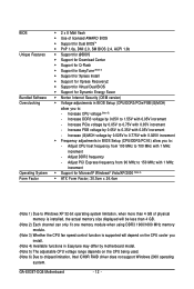
...Hardware Installation A red power connector wire indicates a positive connection and requires a +12V voltage. 3/4/5) CPU_FAN / SYS_FAN1 / SYS_FAN2 / PWR_FAN (Fan Headers) The motherboard has a 4-pin CPU fan header (CPU_FAN), a 3-pin (SYS_FAN1) and a 4-pin (SYS_FAN2) system fan header, and a 3-pin power fan header (PWR_FAN). Do not place a jumper cap on the headers. - 25 - The motherboard supports CPU fan speed control, which requires the use of a CPU fan with color-coded power connector wires. The black connector wire is the ground wire. Each fan header supplies a +12V power voltage...
...Hardware Installation A red power connector wire indicates a positive connection and requires a +12V voltage. 3/4/5) CPU_FAN / SYS_FAN1 / SYS_FAN2 / PWR_FAN (Fan Headers) The motherboard has a 4-pin CPU fan header (CPU_FAN), a 3-pin (SYS_FAN1) and a 4-pin (SYS_FAN2) system fan header, and a 3-pin power fan header (PWR_FAN). Do not place a jumper cap on the headers. - 25 - The motherboard supports CPU fan speed control, which requires the use of a CPU fan with color-coded power connector wires. The black connector wire is the ground wire. Each fan header supplies a +12V power voltage...
Manual
Page 43
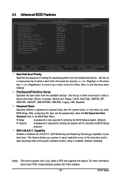
... the list. Options are: Floppy, LS120, Hard Disk, CDROM, ZIP, USB-FDD, USB-ZIP, USB-CDROM, USB-HDD, Legacy LAN, Disabled. Capability Limit CPUID Max. HDD S.M.A.R.T. This feature allows your hard drive. BIOS Setup Password Check Specifies whether a password is required every time the system boots, or only when you install a CPU that supports this item, set the password(s) under the Set Supervisor/User Password item in the BIOS Main Menu. Press to 3 (Note) No-Execute Memory Protect (Note) CPU Enhanced Halt (C1E) (Note) CPU Thermal Monitor...
... the list. Options are: Floppy, LS120, Hard Disk, CDROM, ZIP, USB-FDD, USB-ZIP, USB-CDROM, USB-HDD, Legacy LAN, Disabled. Capability Limit CPUID Max. HDD S.M.A.R.T. This feature allows your hard drive. BIOS Setup Password Check Specifies whether a password is required every time the system boots, or only when you install a CPU that supports this item, set the password(s) under the Set Supervisor/User Password item in the BIOS Main Menu. Press to 3 (Note) No-Execute Memory Protect (Note) CPU Enhanced Halt (C1E) (Note) CPU Thermal Monitor...
Manual
Page 44
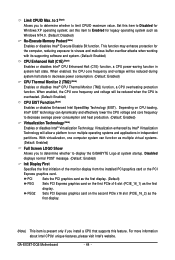
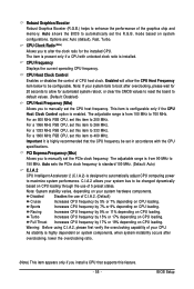
... install a CPU that supports this item to decrease average power consumption and heat production. (Default: Enabled) Virtualization Technology (Note) Enables or disables Intel® Virtualization Technology. Set this feature. PCI Sets the PCI graphics card as the first display. (Default) PEG Sets PCI Express graphics card on the second PCIe x16 slot (PCIE_16_2) as the first display. With virtualization, one computer system can dynamically and effectively lower the CPU voltage and core frequency to Disabled for Windows XP operating system; GA-EX38T-DQ6 Motherboard...
... install a CPU that supports this item to decrease average power consumption and heat production. (Default: Enabled) Virtualization Technology (Note) Enables or disables Intel® Virtualization Technology. Set this feature. PCI Sets the PCI graphics card as the first display. (Default) PEG Sets PCI Express graphics card on the second PCIe x16 slot (PCIE_16_2) as the first display. With virtualization, one computer system can dynamically and effectively lower the CPU voltage and core frequency to Disabled for Windows XP operating system; GA-EX38T-DQ6 Motherboard...
Manual
Page 45
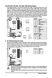
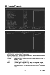
...BIOS Setup 2-5 Integrated Peripherals CMOS Setup Utility-Copyright (C) 1984-2008 Award Software Integrated Peripherals SATA RAID/AHCI Mode SATA Port0-3 Native Mode USB Controller USB 2.0 Controller USB Keyboard Support USB Mouse Support Legacy USB storage detect Azalia Codec Onboard H/W 1394 Onboard H/W LAN1 Onboard H/W LAN2 ` SMART LAN1 ` SMART LAN2 Onboard LAN1 Boot ROM Onboard LAN2 Boot ROM Onboard SATA/IDE Device Onboard SATA/IDE Ctrl Mode Onboard Serial Port 1 Onboard Parallel Port [Disabled] [Disabled] [Enabled] [Enabled] [Disabled] [Disabled] [Enabled] [Auto] [Enabled] [Enabled...
...BIOS Setup 2-5 Integrated Peripherals CMOS Setup Utility-Copyright (C) 1984-2008 Award Software Integrated Peripherals SATA RAID/AHCI Mode SATA Port0-3 Native Mode USB Controller USB 2.0 Controller USB Keyboard Support USB Mouse Support Legacy USB storage detect Azalia Codec Onboard H/W 1394 Onboard H/W LAN1 Onboard H/W LAN2 ` SMART LAN1 ` SMART LAN2 Onboard LAN1 Boot ROM Onboard LAN2 Boot ROM Onboard SATA/IDE Device Onboard SATA/IDE Ctrl Mode Onboard Serial Port 1 Onboard Parallel Port [Disabled] [Disabled] [Enabled] [Enabled] [Disabled] [Disabled] [Enabled] [Auto] [Enabled] [Enabled...

Manual
Page 48
...Auto, 3F8/IRQ4 (default), 2F8/IRQ3, 3E8/IRQ4, 2E8/IRQ3, Disabled. Options are : SPP (Standard Parallel Port)(default), EPP (Enhanced Parallel Port), ECP (Extended Capabilities Port), ECP+EPP. Options are: 378/IRQ7 (default), 278/IRQ5, 3BC/IRQ7, Disabled. GA-EX38T-DQ6 Motherboard - 48 - Parallel Port Mode Selects an operating mode for the SATA controller integrated in the GIGABYTE SATA 2 chip or configures the SATA controller to AHCI mode. IDE Disables RAID for the SATA controller. (The IDE controller still operates in PATA mode) Onboard Serial Port 1 Enables or disables...
...Auto, 3F8/IRQ4 (default), 2F8/IRQ3, 3E8/IRQ4, 2E8/IRQ3, Disabled. Options are : SPP (Standard Parallel Port)(default), EPP (Enhanced Parallel Port), ECP (Extended Capabilities Port), ECP+EPP. Options are: 378/IRQ7 (default), 278/IRQ5, 3BC/IRQ7, Disabled. GA-EX38T-DQ6 Motherboard - 48 - Parallel Port Mode Selects an operating mode for the SATA controller integrated in the GIGABYTE SATA 2 chip or configures the SATA controller to AHCI mode. IDE Disables RAID for the SATA controller. (The IDE controller still operates in PATA mode) Onboard Serial Port 1 Enables or disables...
Manual
Page 53
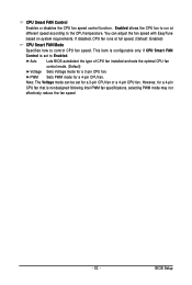
...4-pin CPU fan that is set to control CPU fan speed. If disabled, CPU fan runs at different speed according to the CPU temperature. Auto Lets BIOS autodetect the type of CPU fan installed and sets the optimal CPU fan control mode. (Default) Voltage Sets Voltage mode for a 4-pin CPU fan. Note: The Voltage mode can adjust the fan speed with EasyTune based on system requirements. This item is configurable only if CPU Smart FAN Control is not designed following Intel PWM fan specifications, selecting PWM mode may not effectively reduce the fan speed. - 53 - Enabled allows the CPU fan...
...4-pin CPU fan that is set to control CPU fan speed. If disabled, CPU fan runs at different speed according to the CPU temperature. Auto Lets BIOS autodetect the type of CPU fan installed and sets the optimal CPU fan control mode. (Default) Voltage Sets Voltage mode for a 4-pin CPU fan. Note: The Voltage mode can adjust the fan speed with EasyTune based on system requirements. This item is configurable only if CPU Smart FAN Control is not designed following Intel PWM fan specifications, selecting PWM mode may not effectively reduce the fan speed. - 53 - Enabled allows the CPU fan...
Manual
Page 55
... for automated system reboot, or clear the CMOS values to reset the board to default values. (Default: Disabled) CPU Host Frequency (Mhz) Allows you to manually set the CPU host frequency. As stability is present only if a CPU with the CPU specifications. CPU Clock Ratio (Note) Allows you install a CPU that the CPU frequency be set the R.G.B. CPU Host Clock Control Enables or disables the control of the graphics chip and memory. For a 1600 MHz FSB CPU, set this item to 333 MHz. Note...
... for automated system reboot, or clear the CMOS values to reset the board to default values. (Default: Disabled) CPU Host Frequency (Mhz) Allows you to manually set the CPU host frequency. As stability is present only if a CPU with the CPU specifications. CPU Clock Ratio (Note) Allows you install a CPU that the CPU frequency be set the R.G.B. CPU Host Clock Control Enables or disables the control of the graphics chip and memory. For a 1600 MHz FSB CPU, set this item to 333 MHz. Note...

Manual
Page 60
... & Exit Setup F11: Save CMOS to BIOS F12: Load CMOS from BIOS Save Data to BIOS F12: Load CMOS from BIOS Abandon all Data Press on this item and press the key. GA-EX38T-DQ6 Motherboard - 60 - 2-13 Save & Exit Setup CMOS Setup Utility-Copyright (C) 1984-2008 Award Software ` Standard CMOS Features Load Fail-Safe Defaults ` Advanced BIOS Features Load Optimized Defaults ` Integrated Peripherals Set Supervisor Password ` Power Management Setup Save to CMOS and EXIT (SYe/tNU)?seYr Password ` PnP/PCI Configurations Save & Exit Setup ` PC Health...
... & Exit Setup F11: Save CMOS to BIOS F12: Load CMOS from BIOS Save Data to BIOS F12: Load CMOS from BIOS Abandon all Data Press on this item and press the key. GA-EX38T-DQ6 Motherboard - 60 - 2-13 Save & Exit Setup CMOS Setup Utility-Copyright (C) 1984-2008 Award Software ` Standard CMOS Features Load Fail-Safe Defaults ` Advanced BIOS Features Load Optimized Defaults ` Integrated Peripherals Set Supervisor Password ` Power Management Setup Save to CMOS and EXIT (SYe/tNU)?seYr Password ` PnP/PCI Configurations Save & Exit Setup ` PC Health...
Manual
Page 71
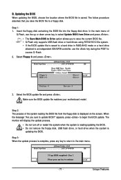
... supports USB flash drive or hard drives using FAT32/16/12 file system. • If the BIOS update file is complete, press any keEyStCo:Rcoensetitnue F10:Power Off - 71 - Select the BIOS update file and press . Make sure the BIOS update file matches your motherboard model. appears, press to update BIOS?" Unique Features Insert the floppy disk containing the BIOS file into the floppy disk drive. Save BIOS to a floppy disk. Q-Flash Utility v2.05 Flash Type/Size SST 25VF080B 1M Enter : Run Keep DMI Data Enable !! The monitor will display...
... supports USB flash drive or hard drives using FAT32/16/12 file system. • If the BIOS update file is complete, press any keEyStCo:Rcoensetitnue F10:Power Off - 71 - Select the BIOS update file and press . Make sure the BIOS update file matches your motherboard model. appears, press to update BIOS?" Unique Features Insert the floppy disk containing the BIOS file into the floppy disk drive. Save BIOS to a floppy disk. Q-Flash Utility v2.05 Flash Type/Size SST 25VF080B 1M Enter : Run Keep DMI Data Enable !! The monitor will display...
Manual
Page 79
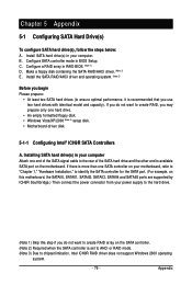
... and SATAII5 ports are supported by ICH9R Southbridge.) Then connect the power connector from your power supply to the hard drive. (Note 1) Skip this step if you begin Please prepare: • At least two SATA hard drives (to available SATA port on the motherboard. Configure a RAID array in BIOS Setup. Installing SATA hard drive(s) in your computer Attach one hard drive. • An empty formatted floppy disk. • Windows Vista/XP/2000 (Note 3) setup disk. • Motherboard driver disk. 5-1-1 Configuring Intel® ICH9R SATA Controllers A. Appendix...
... and SATAII5 ports are supported by ICH9R Southbridge.) Then connect the power connector from your power supply to the hard drive. (Note 1) Skip this step if you begin Please prepare: • At least two SATA hard drives (to available SATA port on the motherboard. Configure a RAID array in BIOS Setup. Installing SATA hard drive(s) in your computer Attach one hard drive. • An empty formatted floppy disk. • Windows Vista/XP/2000 (Note 3) setup disk. • Motherboard driver disk. 5-1-1 Configuring Intel® ICH9R SATA Controllers A. Appendix...

Manual
Page 85
... Setup Utility-Copyright (C) 1984-2008 Award Software Integrated Peripherals SATA RAID/AHCI Mode SATA Port0-3 Native Mode USB Controller USB 2.0 Controller USB Keyboard Support USB Mouse Support Legacy USB storage detect Azalia Codec Onboard H/W 1394 Onboard H/W LAN1 Onboard H/W LAN2 ` SMART LAN1 ` SMART LAN2 Onboard LAN1 Boot ROM Onboard LAN2 Boot ROM Onboard SATA/IDE Device Onboard SATA/IDE Ctrl Mode Onboard Serial Port 1 Onboard Parallel Port [Disabled] [Disabled] [Enabled] [Enabled] [Disabled] [Disabled] [Enabled] [Auto] [Enabled] [Enabled] [Enabled] [Press Enter] [Press Enter] [Disabled...
... Setup Utility-Copyright (C) 1984-2008 Award Software Integrated Peripherals SATA RAID/AHCI Mode SATA Port0-3 Native Mode USB Controller USB 2.0 Controller USB Keyboard Support USB Mouse Support Legacy USB storage detect Azalia Codec Onboard H/W 1394 Onboard H/W LAN1 Onboard H/W LAN2 ` SMART LAN1 ` SMART LAN2 Onboard LAN1 Boot ROM Onboard LAN2 Boot ROM Onboard SATA/IDE Device Onboard SATA/IDE Ctrl Mode Onboard Serial Port 1 Onboard Parallel Port [Disabled] [Disabled] [Enabled] [Enabled] [Disabled] [Disabled] [Enabled] [Auto] [Enabled] [Enabled] [Enabled] [Press Enter] [Press Enter] [Disabled...
Manual
Page 86
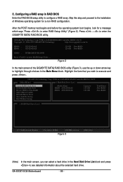
... GIGABYTE SATA2 RAID BIOS utility. GIGABYTE Technology Corp. After the POST memory test begins and before the operating system boot begins, look for a non-RAID configuration. PCIE-to-SATAII/IDE RAID Controller BIOSv1.06.59 [ Main Menu ] [ Hard Disk Drive List ] Create RAID Disk Drive Delete RAID Disk Drive Revert HDD to Non-RAID Solve Mirror Conflict Rebuild Mirror Drive Save And Exit Setup Exit Without Saving Model Name HDD0: ST3120026AS HDD1: ST3120026AS Capacity 120 GB 120 GB Type/Status Non-RAID Non-RAID [ RAID Disk Drive List ] [IJTAB]-Switch Window...
... GIGABYTE SATA2 RAID BIOS utility. GIGABYTE Technology Corp. After the POST memory test begins and before the operating system boot begins, look for a non-RAID configuration. PCIE-to-SATAII/IDE RAID Controller BIOSv1.06.59 [ Main Menu ] [ Hard Disk Drive List ] Create RAID Disk Drive Delete RAID Disk Drive Revert HDD to Non-RAID Solve Mirror Conflict Rebuild Mirror Drive Save And Exit Setup Exit Without Saving Model Name HDD0: ST3120026AS HDD1: ST3120026AS Capacity 120 GB 120 GB Type/Status Non-RAID Non-RAID [ RAID Disk Drive List ] [IJTAB]-Switch Window...
Manual
Page 91
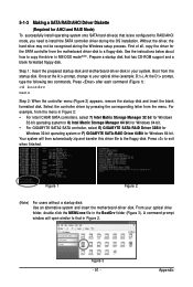
... menu. Once at the A:\> prompt, change to copy the driver in Figure 2. First of all, copy the driver for Windows 64-bit. Prepare a startup disk that in MS-DOS mode(Note). At the D:\> prompt, type the following two commands. Your system will open similar to a floppy disk. 5-1-3 Making a SATA RAID/AHCI Driver Diskette (Required for AHCI and RAID Mode) To successfully install operating system onto SATA hard drive(s) that is/are configured to RAID/AHCI mode...
... menu. Once at the A:\> prompt, change to copy the driver in Figure 2. First of all, copy the driver for Windows 64-bit. Prepare a startup disk that in MS-DOS mode(Note). At the D:\> prompt, type the following two commands. Your system will open similar to a floppy disk. 5-1-3 Making a SATA RAID/AHCI Driver Diskette (Required for AHCI and RAID Mode) To successfully install operating system onto SATA hard drive(s) that is/are configured to RAID/AHCI mode...

Manual
Page 92
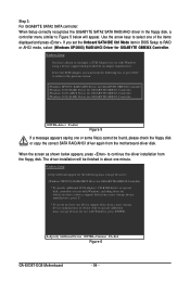
...-ROM drives, or special disk controllers for which you have a device support disk from a mass storage device manufacturer, or do not have prepared the SATA RAID/AHCI driver diskette and configured the required BIOS settings, you are ready to install Windows Vista/XP/2000 onto your system, or you do not want to specify additional mass storage devices for use with Windows, including those for use with Windows, press ENTER. Windows Setup Setup could not determine the type of...
...-ROM drives, or special disk controllers for which you have a device support disk from a mass storage device manufacturer, or do not have prepared the SATA RAID/AHCI driver diskette and configured the required BIOS settings, you are ready to install Windows Vista/XP/2000 onto your system, or you do not want to specify additional mass storage devices for use with Windows, including those for use with Windows, press ENTER. Windows Setup Setup could not determine the type of...
Manual
Page 94
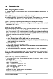
... Controller (Windows 2000) AHCI Driver for GIGABYTE GBB363 Controller (Windows 2000) RAID Driver for use with Windows, using a device support disk provided by an adapter manufacturer. Use the arrow keys to configure a SCSI Adapter for GIGABYTE GBB360 Controller ENTER=Select F3=Exit Figure 5 If a message appears saying one minute. When the screen as shown below appears, press to specify additional mass storage devices for which you have a device support disk from a mass storage device manufacturer, press S. * If you set the Onboard SATA/IDE...
... Controller (Windows 2000) AHCI Driver for GIGABYTE GBB363 Controller (Windows 2000) RAID Driver for use with Windows, using a device support disk provided by an adapter manufacturer. Use the arrow keys to configure a SCSI Adapter for GIGABYTE GBB360 Controller ENTER=Select F3=Exit Figure 5 If a message appears saying one minute. When the screen as shown below appears, press to specify additional mass storage devices for which you have a device support disk from a mass storage device manufacturer, press S. * If you set the Onboard SATA/IDE...

Manual
Page 105
... Step 1: After installing the audio driver, the Audio Manager icon will appear in your system tray. Then configure the jack for microphone functionality. Step 3: Locate the Volume icon in your system tray and click it to open the volume control panel. - 105 - Note: The microphone functions on the front panel. Appendix Doubleclick the icon to be used at the same...
... Step 1: After installing the audio driver, the Audio Manager icon will appear in your system tray. Then configure the jack for microphone functionality. Step 3: Locate the Volume icon in your system tray and click it to open the volume control panel. - 105 - Note: The microphone functions on the front panel. Appendix Doubleclick the icon to be used at the same...
Manual
Page 110
...: CMOS setting error 1 long, 1 short: Memory or motherboard error 1 long, 2 short: Monitor or graphics card error 1 long, 3 short: Keyboard error 1 long, 9 short: BIOS ROM error Continuous long beeps: Graphics card not inserted properly Continuous short beeps: Power error GA-EX38T-DQ6 Motherboard - 110 - A: Make sure your speaker is the light of the battery holder, making them short for one minute. (Or use a metal object like a screwdriver to the instructions on . You can temporarily remove the battery from the battery holder and wait for 5 seconds.) 3. A: Some advanced options...
...: CMOS setting error 1 long, 1 short: Memory or motherboard error 1 long, 2 short: Monitor or graphics card error 1 long, 3 short: Keyboard error 1 long, 9 short: BIOS ROM error Continuous long beeps: Graphics card not inserted properly Continuous short beeps: Power error GA-EX38T-DQ6 Motherboard - 110 - A: Make sure your speaker is the light of the battery holder, making them short for one minute. (Or use a metal object like a screwdriver to the instructions on . You can temporarily remove the battery from the battery holder and wait for 5 seconds.) 3. A: Some advanced options...


