Manual
Page 1
GA-EX38T-DQ6 LGA775 socket motherboard for Intel® CoreTM processor family/ Intel® Pentium® processor family/Intel® Celeron® processor family User's Manual Rev. 1101 12ME-EX38TDQ6-1101R
GA-EX38T-DQ6 LGA775 socket motherboard for Intel® CoreTM processor family/ Intel® Pentium® processor family/Intel® Celeron® processor family User's Manual Rev. 1101 12ME-EX38TDQ6-1101R

Manual
Page 2
Motherboard GA-EX38T-DQ6 Feb. 22, 2008 Motherboard GA-EX38T-DQ6 Feb. 22, 2008
Motherboard GA-EX38T-DQ6 Feb. 22, 2008 Motherboard GA-EX38T-DQ6 Feb. 22, 2008
Manual
Page 3
... to their respective owners. For product-related information, check on our website at: http://www.gigabyte.com.tw Identifying Your Motherboard Revision The revision number on our website. The logo is 1.0. Check your motherboard looks like this: "REV: X.X." GIGABYTE UNITED INC. Example: The trademarks mentioned in any means without prior notice. All rights reserved...
... to their respective owners. For product-related information, check on our website at: http://www.gigabyte.com.tw Identifying Your Motherboard Revision The revision number on our website. The logo is 1.0. Check your motherboard looks like this: "REV: X.X." GIGABYTE UNITED INC. Example: The trademarks mentioned in any means without prior notice. All rights reserved...
Manual
Page 4
Table of Contents Box Contents ...6 OptionalItems ...6 GA-EX38T-DQ6 Motherboard Layout 7 Block Diagram ...8 Chapter 1 Hardware Installation 9 1-1 Installation Precautions 9 1-2 Product Specifications 10 1-3 Installing the CPU and CPU Cooler 13 1-3-1 Installing the CPU 13 1-3-2 Installing the CPU Cooler 15 1-3-3 Removing the Crazy Cool Heatsink from the Back of the Motherboard ..... 16 1-4 Installing the Memory 17 1-4-1 Dual Channel Memory...
Table of Contents Box Contents ...6 OptionalItems ...6 GA-EX38T-DQ6 Motherboard Layout 7 Block Diagram ...8 Chapter 1 Hardware Installation 9 1-1 Installation Precautions 9 1-2 Product Specifications 10 1-3 Installing the CPU and CPU Cooler 13 1-3-1 Installing the CPU 13 1-3-2 Installing the CPU Cooler 15 1-3-3 Removing the Crazy Cool Heatsink from the Back of the Motherboard ..... 16 1-4 Installing the Memory 17 1-4-1 Dual Channel Memory...

Manual
Page 6
Box Contents GA-EX38T-DQ6 motherboard Motherboard driver disk User's Manual Quick Installation Guide Intel® LGA775 CPU Installation Guide One IDE cable and one floppy disk drive cable Four SATA 3Gb/s cables Two SATA brackets I/O Shield Two screw nuts • The box contents above are subject to change without notice. • The motherboard image is for...
Box Contents GA-EX38T-DQ6 motherboard Motherboard driver disk User's Manual Quick Installation Guide Intel® LGA775 CPU Installation Guide One IDE cable and one floppy disk drive cable Four SATA 3Gb/s cables Two SATA brackets I/O Shield Two screw nuts • The box contents above are subject to change without notice. • The motherboard image is for...
Manual
Page 7
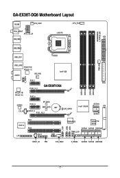
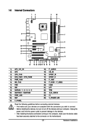
GA-EX38T-DQ6 Motherboard Layout KB_MS SYS_FAN1 CPU_FAN RCA_SPDIF ATX_12V_2X LGA775 ATX USB_1394_1 V_PHASE LED USB_1394_2 USB_LAN PWR_FAN USB_LAN2 RTL8111B/ RTL8111C AUDIO NB_FAN Intel® X38 F_AUDIO RTL8111B/ RTL8111C PCIE_1 PCIE_16_1 GA-EX38T-DQ6 PCIE_2 CODEC CD_IN PCIE_3 BP_BIOS MAIN_BIOS BAT ...SPDIF_O PCIE_16_2 CLR_CMOS FDD DDRIII1 DDRIII2 DDRIII3 DDRIII4 Intel® ICH9R SATAII0 IDE SATAII1 PCI1 IT8718 PCI2 CI COM LPT F_1394 F_USB2 F_USB1 TSB43AB23 GIGABYTE SATA2 ...
GA-EX38T-DQ6 Motherboard Layout KB_MS SYS_FAN1 CPU_FAN RCA_SPDIF ATX_12V_2X LGA775 ATX USB_1394_1 V_PHASE LED USB_1394_2 USB_LAN PWR_FAN USB_LAN2 RTL8111B/ RTL8111C AUDIO NB_FAN Intel® X38 F_AUDIO RTL8111B/ RTL8111C PCIE_1 PCIE_16_1 GA-EX38T-DQ6 PCIE_2 CODEC CD_IN PCIE_3 BP_BIOS MAIN_BIOS BAT ...SPDIF_O PCIE_16_2 CLR_CMOS FDD DDRIII1 DDRIII2 DDRIII3 DDRIII4 Intel® ICH9R SATAII0 IDE SATAII1 PCI1 IT8718 PCI2 CI COM LPT F_1394 F_USB2 F_USB1 TSB43AB23 GIGABYTE SATA2 ...

Manual
Page 9
.... If you do not have an ESD wrist strap, keep your hardware components are connected. • To prevent damage to the motherboard, do not remove or break motherboard S/N (Serial Number) sticker or warranty sticker provided by unplugging the power cord from the power outlet before installing or removing the... all cables and power connectors of your hands dry and first touch a metal object to eliminate static electricity. • Prior to installing the motherboard, please have it on top of an antistatic pad or within the computer casing. • Do not place the computer system on an uneven...
.... If you do not have an ESD wrist strap, keep your hardware components are connected. • To prevent damage to the motherboard, do not remove or break motherboard S/N (Serial Number) sticker or warranty sticker provided by unplugging the power cord from the power outlet before installing or removing the... all cables and power connectors of your hands dry and first touch a metal object to eliminate static electricity. • Prior to installing the motherboard, please have it on top of an antistatic pad or within the computer casing. • Do not place the computer system on an uneven...

Manual
Page 10
...GIGABYTE SATA2 chip: - 1 x IDE connector supporting ATA-133/100/66/33 and up to 2 IDE devices - 2 x SATA 3Gb/s connectors (GSATAIIA, GSATAIIB) supporting up to 2 SATA 3Gb/s devices - TSB43AB23 chip Š Up to 3 IEEE 1394a ports (2 on the back panel, 1 via the IEEE 1394a bracket connected to the internal IEEE 1394a header) GA-EX38T-DQ6 Motherboard... Dual channel memory architecture (Note 2) Š Support for DDR3 1900/1600/1333/1066/800 MHz memory modules (Go to GIGABYTE's website for the latest memory support list.) Š Support for ECC memory Š Realtek ALC889A codec Š High ...
...GIGABYTE SATA2 chip: - 1 x IDE connector supporting ATA-133/100/66/33 and up to 2 IDE devices - 2 x SATA 3Gb/s connectors (GSATAIIA, GSATAIIB) supporting up to 2 SATA 3Gb/s devices - TSB43AB23 chip Š Up to 3 IEEE 1394a ports (2 on the back panel, 1 via the IEEE 1394a bracket connected to the internal IEEE 1394a header) GA-EX38T-DQ6 Motherboard... Dual channel memory architecture (Note 2) Š Support for DDR3 1900/1600/1333/1066/800 MHz memory modules (Go to GIGABYTE's website for the latest memory support list.) Š Support for ECC memory Š Realtek ALC889A codec Š High ...
Manual
Page 12
... BIOS Setup (CPU/DDR3/PCIe/FSB/(G)MCH) allow you to 700 MHz with 0.05V increment - Increase CPU voltage (Note 5) - Adjust DDR3 frequency - GA-EX38T-DQ6 Motherboard - 12 - Increase FSB voltage by 0.05V to 0.75V with 1 MHz increment - Increase PCIe voltage by 0.05V to 0.35V with 0.05V increment -... the CPU fan speed control function is supported will depend on the CPU cooler you install. (Note 4) Available functions in Easytune may differ by motherboard model. (Note 5) The adjustable CPU voltage range depends on the CPU being used. (Note 6) Due to : - Increase DDR3 voltage by ...
... BIOS Setup (CPU/DDR3/PCIe/FSB/(G)MCH) allow you to 700 MHz with 0.05V increment - Increase CPU voltage (Note 5) - Adjust DDR3 frequency - GA-EX38T-DQ6 Motherboard - 12 - Increase FSB voltage by 0.05V to 0.75V with 1 MHz increment - Increase PCIe voltage by 0.05V to 0.35V with 0.05V increment -... the CPU fan speed control function is supported will depend on the CPU cooler you install. (Note 4) Available functions in Easytune may differ by motherboard model. (Note 5) The adjustable CPU voltage range depends on the CPU being used. (Note 6) Due to : - Increase DDR3 voltage by ...
Manual
Page 13
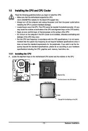
... One Corner of the CPU Socket Notch Notch Triangle Pin One Marking on the CPU. mended that the motherboard supports the CPU. (Go to GIGABYTE's website for the peripherals. Locate the alignment keys on the motherboard CPU socket and the notches on the CPU - 13 - 1-3 Installing the CPU and CPU Cooler Read the...
... One Corner of the CPU Socket Notch Notch Triangle Pin One Marking on the CPU. mended that the motherboard supports the CPU. (Go to GIGABYTE's website for the peripherals. Locate the alignment keys on the motherboard CPU socket and the notches on the CPU - 13 - 1-3 Installing the CPU and CPU Cooler Read the...

Manual
Page 14
Follow the steps below to the CPU. Step 3: Lift the metal load plate on the CPU socket. Step 2: Remove the protective socket cover. GA-EX38T-DQ6 Motherboard - 14 - CPU Socket Lever Step 1: Completely raise the CPU socket lever. Align the CPU pin one marking (triangle) with the pin one corner...CPU notches with your thumb and index fingers. Step 4: Hold the CPU with the socket alignment keys) and gently insert the CPU into the motherboard CPU socket. B. Before installing the CPU, make sure to turn off the computer and unplug the power cord from the power outlet to ...
Follow the steps below to the CPU. Step 3: Lift the metal load plate on the CPU socket. Step 2: Remove the protective socket cover. GA-EX38T-DQ6 Motherboard - 14 - CPU Socket Lever Step 1: Completely raise the CPU socket lever. Align the CPU pin one marking (triangle) with the pin one corner...CPU notches with your thumb and index fingers. Step 4: Hold the CPU with the socket alignment keys) and gently insert the CPU into the motherboard CPU socket. B. Before installing the CPU, make sure to turn off the computer and unplug the power cord from the power outlet to ...
Manual
Page 15
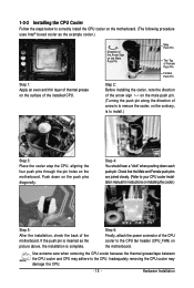
1-3-2 Installing the CPU Cooler Follow the steps below to correctly install the CPU cooler on the motherboard. (The following procedure uses Intel® boxed cooler as the picture above, the installation is to the CPU fan header (CPU_FAN) on the push pins ... to install.) Step 3: Place the cooler atop the CPU, aligning the four push pins through the pin holes on the motherboard. Step 4: You should hear a "click" when pushing down on the motherboard. If the push pin is inserted as the example cooler.) Step 1: Apply an even and thin layer of thermal grease...
1-3-2 Installing the CPU Cooler Follow the steps below to correctly install the CPU cooler on the motherboard. (The following procedure uses Intel® boxed cooler as the picture above, the installation is to the CPU fan header (CPU_FAN) on the push pins ... to install.) Step 3: Place the cooler atop the CPU, aligning the four push pins through the pin holes on the motherboard. Step 4: You should hear a "click" when pushing down on the motherboard. If the push pin is inserted as the example cooler.) Step 1: Apply an even and thin layer of thermal grease...
Manual
Page 16
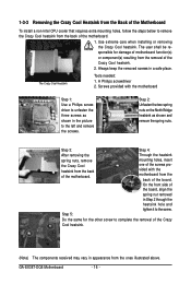
... picture to the left and remove the screws. The Crazy Cool Heatsink Tools needed: 1. Step 5: Do the same for damage of motherboard function(s) or component(s) resulting from the ones illustrated above. Step 3: Step 4: After removing the spring nuts, remove the Crazy Cool ... Back of the Motherboard To install a non-Intel CPU cooler that requires extra mounting holes, follow the steps below to remove the Crazy Cool heatsink from the back of the motherboard. A Philips screwdriver 2. Use extreme care when installing or removing the Crazy Cool heatsink. GA-EX38T-DQ6 Motherboard - 16 -
... picture to the left and remove the screws. The Crazy Cool Heatsink Tools needed: 1. Step 5: Do the same for damage of motherboard function(s) or component(s) resulting from the ones illustrated above. Step 3: Step 4: After removing the spring nuts, remove the Crazy Cool ... Back of the Motherboard To install a non-Intel CPU cooler that requires extra mounting holes, follow the steps below to remove the Crazy Cool heatsink from the back of the motherboard. A Philips screwdriver 2. Use extreme care when installing or removing the Crazy Cool heatsink. GA-EX38T-DQ6 Motherboard - 16 -
Manual
Page 17
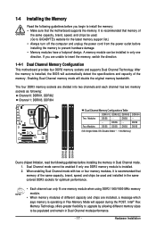
.... 1. Intel® Flex Memory Technology offers greater flexibility to upgrade by allowing different memory sizes to be used. (Go to GIGABYTE's website for optimum performance. • Each channel can be used and installed in the same colored DDR3 sockets for the latest ...Double-Sided, "- -"=No Memory) DDRIII1 DDRIII2 DDRIII3 DDRIII4 Due to insert the memory, switch the direction. 1-4-1 Dual Channel Memory Configuration This motherboard provides four DDR3 memory sockets and supports Dual Channel Technology. DS/SS - - A memory module can only fit one direction. Enabling Dual...
.... 1. Intel® Flex Memory Technology offers greater flexibility to upgrade by allowing different memory sizes to be used. (Go to GIGABYTE's website for optimum performance. • Each channel can be used and installed in the same colored DDR3 sockets for the latest ...Double-Sided, "- -"=No Memory) DDRIII1 DDRIII2 DDRIII3 DDRIII4 Due to insert the memory, switch the direction. 1-4-1 Dual Channel Memory Configuration This motherboard provides four DDR3 memory sockets and supports Dual Channel Technology. DS/SS - - A memory module can only fit one direction. Enabling Dual...

Manual
Page 18
... on the socket. DDR3 and DDR2 DIMMs are not compatible to each other or DDR DIMMs. Be sure to correctly install your fingers on this motherboard. GA-EX38T-DQ6 Motherboard - 18 - 1-4-2 Installing a Memory Before installing a memory module , make sure to turn off the computer and unplug the power cord from the power outlet to prevent...
... on the socket. DDR3 and DDR2 DIMMs are not compatible to each other or DDR DIMMs. Be sure to correctly install your fingers on this motherboard. GA-EX38T-DQ6 Motherboard - 18 - 1-4-2 Installing a Memory Before installing a memory module , make sure to turn off the computer and unplug the power cord from the power outlet to prevent...
Manual
Page 19
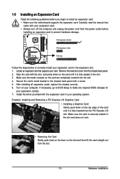
... that supports your computer. Remove the metal slot cover from the power outlet before you begin to install an expansion card: • Make sure the motherboard supports the expansion card. After installing all expansion cards, replace the chassis cover(s). 6. If necessary, go to BIOS Setup to prevent hardware damage. Hardware Installation...
... that supports your computer. Remove the metal slot cover from the power outlet before you begin to install an expansion card: • Make sure the motherboard supports the expansion card. After installing all expansion cards, replace the chassis cover(s). 6. If necessary, go to BIOS Setup to prevent hardware damage. Hardware Installation...
Manual
Page 20
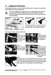
... SATA bracket to the chassis back panel with a screw. Before connecting the SATA signal cable, make sure to the SATA port on Step 5: the bracket. GA-EX38T-DQ6 Motherboard - 20 - Follow the steps below to hardware. • Insert the SATA signal cable and SATA power cable securely into to connect the SATA signal cable... and the power switch on the bracket. Step 3: Step 4: Connect the power Plug one end of the cable from the bracket to turn off your motherboard. 1-6 Installing the SATA Bracket The SATA bracket allows you only need to the power supply.
... SATA bracket to the chassis back panel with a screw. Before connecting the SATA signal cable, make sure to the SATA port on Step 5: the bracket. GA-EX38T-DQ6 Motherboard - 20 - Follow the steps below to hardware. • Insert the SATA signal cable and SATA power cable securely into to connect the SATA signal cable... and the power switch on the bracket. Step 3: Step 4: Connect the power Plug one end of the cable from the bracket to turn off your motherboard. 1-6 Installing the SATA Bracket The SATA bracket allows you only need to the power supply.
Manual
Page 21
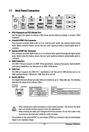
... Connector This connector provides digital audio out to connect a PS/2 keyboard. Before using this feature, ensure that your device and then remove it from the motherboard. • When removing the cable, pull it side to side to prevent an electrical short inside the cable connector. * The positions of the LAN port...
... Connector This connector provides digital audio out to connect a PS/2 keyboard. Before using this feature, ensure that your device and then remove it from the motherboard. • When removing the cable, pull it side to side to prevent an electrical short inside the cable connector. * The positions of the LAN port...
Manual
Page 22
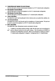
... microphones still MUST be reconfigured to perform different functions via the audio software. Microphones must be used to connect front speakers in a 4/5.1/7.1-channel audio configuration. GA-EX38T-DQ6 Motherboard - 22 - Use this audio jack for a headphone or 2-channel speaker. Refer to the instructions on setting up a 2/4/5.1/ 7.1-channel audio configuration in a 7.1-channel audio configuration. Side...
... microphones still MUST be reconfigured to perform different functions via the audio software. Microphones must be used to connect front speakers in a 4/5.1/7.1-channel audio configuration. GA-EX38T-DQ6 Motherboard - 22 - Use this audio jack for a headphone or 2-channel speaker. Refer to the instructions on setting up a 2/4/5.1/ 7.1-channel audio configuration in a 7.1-channel audio configuration. Side...
Manual
Page 23
..., make sure your devices are compliant with the connectors you wish to connect. • Before installing the devices, be sure to the connector on the motherboard. - 23 - Unplug the power cord from the power outlet to prevent damage to the devices. • After installing the device and before connecting external devices...
..., make sure your devices are compliant with the connectors you wish to connect. • Before installing the devices, be sure to the connector on the motherboard. - 23 - Unplug the power cord from the power outlet to prevent damage to the devices. • After installing the device and before connecting external devices...


