Manual
Page 3
... Example: Check your motherboard looks like this: "REV: X.X." For product-related information, check on our website at: http://www.gigabyte.com.tw Identifying Your Motherboard Revision The revision number on our website. The trademarks mentioned in this manual may be reproduced, copied... Guide page on your motherboard revision before updating motherboard BIOS, drivers, or when looking for technical information. is exclusively licensed to use of this manual may be made by any form or by GIGABYTE without GIGABYTE's prior written permission. Copyright © 2008 GIGA-...
... Example: Check your motherboard looks like this: "REV: X.X." For product-related information, check on our website at: http://www.gigabyte.com.tw Identifying Your Motherboard Revision The revision number on our website. The trademarks mentioned in this manual may be reproduced, copied... Guide page on your motherboard revision before updating motherboard BIOS, drivers, or when looking for technical information. is exclusively licensed to use of this manual may be made by any form or by GIGABYTE without GIGABYTE's prior written permission. Copyright © 2008 GIGA-...
Manual
Page 4
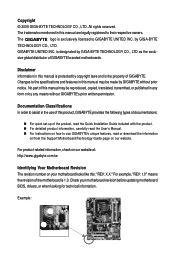
Table of Contents Box Contents ...6 OptionalItems ...6 GA-EX38T-DQ6 Motherboard Layout 7 Block Diagram ...8 Chapter 1 Hardware Installation 9 1-1 Installation Precautions 9 1-2 Product Specifications 10 1-3 Installing the CPU and CPU Cooler 13 ... Card 19 1-6 Installing the SATA Bracket 20 1-7 Back Panel Connectors 21 1-8 Internal Connectors 23 Chapter 2 BIOS Setup 37 2-1 Startup Screen 38 2-2 The Main Menu 39 2-3 Standard CMOS Features 41 2-4 Advanced BIOS Features 43 2-5 IntegratedPeripherals 45 2-6 Power Management Setup 49 2-7 PnP/PCI Configurations 51 2-8 PC Health Status...
Table of Contents Box Contents ...6 OptionalItems ...6 GA-EX38T-DQ6 Motherboard Layout 7 Block Diagram ...8 Chapter 1 Hardware Installation 9 1-1 Installation Precautions 9 1-2 Product Specifications 10 1-3 Installing the CPU and CPU Cooler 13 ... Card 19 1-6 Installing the SATA Bracket 20 1-7 Back Panel Connectors 21 1-8 Internal Connectors 23 Chapter 2 BIOS Setup 37 2-1 Startup Screen 38 2-2 The Main Menu 39 2-3 Standard CMOS Features 41 2-4 Advanced BIOS Features 43 2-5 IntegratedPeripherals 45 2-6 Power Management Setup 49 2-7 PnP/PCI Configurations 51 2-8 PC Health Status...
Manual
Page 5
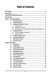
...63 3-5 Contact Us ...63 Chapter 4 Unique Features 65 4-1 Xpress Recovery2 65 4-2 BIOS Update Utilities 70 4-2-1 Updating the BIOS with the Q-Flash Utility 70 4-2-2 Updating the BIOS with the @BIOS Utility 73 4-3 EasyTune 5 Pro 75 4-4 Dynamic Energy Saver 76 4-5 Windows Vista ...ReadyBoost 78 Chapter 5 Appendix ...79 5-1 Configuring SATA Hard Drive(s 79 5-1-1 Configuring Intel® ICH9R SATA Controllers 79 5-1-2 Configuring GIGABYTE...
...63 3-5 Contact Us ...63 Chapter 4 Unique Features 65 4-1 Xpress Recovery2 65 4-2 BIOS Update Utilities 70 4-2-1 Updating the BIOS with the Q-Flash Utility 70 4-2-2 Updating the BIOS with the @BIOS Utility 73 4-3 EasyTune 5 Pro 75 4-4 Dynamic Energy Saver 76 4-5 Windows Vista ...ReadyBoost 78 Chapter 5 Appendix ...79 5-1 Configuring SATA Hard Drive(s 79 5-1-1 Configuring Intel® ICH9R SATA Controllers 79 5-1-2 Configuring GIGABYTE...

Manual
Page 8
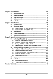
...) RJ45 RJ45 RTL RTL 8111B/ 8111B/ 8111C 8111C x1 x1 x1 x1 x1 PCI Express Bus 2 SATA 3Gb/s ATA-133/100/66/ 33 IDE Channel GIGABYTE SATA2 PCI Bus TSB43AB23 3 IEEE 1394a Host Interface Intel® X38 Intel® ICH9R CODEC DDR3 1900/1600/1333/ 1066/800 MHz Dual Channel Memory... MCH CLK (400/333/266/200 MHz) Dual BIOS 6 SATA 3Gb/s 12 USB Ports IT8718 Floppy LPT Port COM Port PS/2 KB/Mouse TPM 2 PCI PCI CLK (33 MHz) Surround Speaker Out Center/Subwoofer...
...) RJ45 RJ45 RTL RTL 8111B/ 8111B/ 8111C 8111C x1 x1 x1 x1 x1 PCI Express Bus 2 SATA 3Gb/s ATA-133/100/66/ 33 IDE Channel GIGABYTE SATA2 PCI Bus TSB43AB23 3 IEEE 1394a Host Interface Intel® X38 Intel® ICH9R CODEC DDR3 1900/1600/1333/ 1066/800 MHz Dual Channel Memory... MCH CLK (400/333/266/200 MHz) Dual BIOS 6 SATA 3Gb/s 12 USB Ports IT8718 Floppy LPT Port COM Port PS/2 KB/Mouse TPM 2 PCI PCI CLK (33 MHz) Surround Speaker Out Center/Subwoofer...
Manual
Page 12
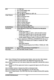
... Security (OEM version) Š Voltage adjustments in BIOS Setup (CPU/DDR3/PCIe/FSB/(G)MCH) allow you to 0.75V with 0.05V increment - Adjust PCI Express frequency from 100 MHz to 700 MHz with 1 MHz increment - GA-EX38T-DQ6 Motherboard - 12 - Increase PCIe voltage by 0.025V... to 0.775V with 0.025V increment Š Frequency adjustments in BIOS Setup (CPU/DDR3/PCI-E) allow you to: - BIOS Unique Features Bundled Software Overclocking Operating System Form Factor Š ...
... Security (OEM version) Š Voltage adjustments in BIOS Setup (CPU/DDR3/PCIe/FSB/(G)MCH) allow you to 0.75V with 0.05V increment - Adjust PCI Express frequency from 100 MHz to 700 MHz with 1 MHz increment - GA-EX38T-DQ6 Motherboard - 12 - Increase PCIe voltage by 0.025V... to 0.775V with 0.025V increment Š Frequency adjustments in BIOS Setup (CPU/DDR3/PCI-E) allow you to: - BIOS Unique Features Bundled Software Overclocking Operating System Form Factor Š ...
Manual
Page 17
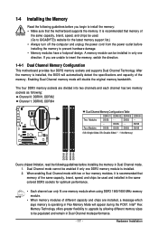
It is installed, the BIOS will automatically detect the specifications and capacity of the same capacity, brand, speed, and chips be installed in Dual Channel mode/performance. - 17 - DS/SS - - ..., brand, speed, and chips be used and installed in the same colored DDR3 sockets for optimum performance. • Each channel can be used . (Go to GIGABYTE's website for the latest memory support list.) • Always turn off the computer and unplug the power cord from the power outlet before installing the...
It is installed, the BIOS will automatically detect the specifications and capacity of the same capacity, brand, speed, and chips be installed in Dual Channel mode/performance. - 17 - DS/SS - - ..., brand, speed, and chips be used and installed in the same colored DDR3 sockets for optimum performance. • Each channel can be used . (Go to GIGABYTE's website for the latest memory support list.) • Always turn off the computer and unplug the power cord from the power outlet before installing the...
Manual
Page 19
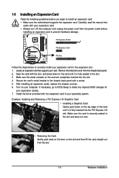
... power outlet before you begin to install an expansion card: • Make sure the motherboard supports the expansion card. If necessary, go to BIOS Setup to make any required BIOS changes for your expansion card in the slot. 3. After installing all expansion cards, replace the chassis cover(s). 6. Remove the metal slot cover...
... power outlet before you begin to install an expansion card: • Make sure the motherboard supports the expansion card. If necessary, go to BIOS Setup to make any required BIOS changes for your expansion card in the slot. 3. After installing all expansion cards, replace the chassis cover(s). 6. Remove the metal slot cover...
Manual
Page 28
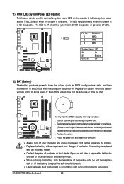
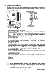
...: 1. Replace the battery. 4. Definition 1 1 MPD+ 2 MPD- 3 MPD- You may be handled in S1 sleep state. Danger of the battery holder, making them short for one . GA-EX38T-DQ6 Motherboard - 28 - Pin No. Plug in the CMOS when the computer is turned off your computer and unplug the power cord. 2. Gently remove the battery...battery (the positive side should face up). • Used batteries must be lost. The LED is on the chassis to keep the values (such as BIOS configurations, date, and time information) in the power cord and restart your computer. • Always turn off .
...: 1. Replace the battery. 4. Definition 1 1 MPD+ 2 MPD- 3 MPD- You may be handled in S1 sleep state. Danger of the battery holder, making them short for one . GA-EX38T-DQ6 Motherboard - 28 - Pin No. Plug in the CMOS when the computer is turned off your computer and unplug the power cord. 2. Gently remove the battery...battery (the positive side should face up). • Used batteries must be lost. The LED is on the chassis to keep the values (such as BIOS configurations, date, and time information) in the power cord and restart your computer. • Always turn off .
Manual
Page 29
...): System Status LED Connects to the reset switch on the chassis front panel. When connecting your system using the power switch (refer to Chapter 2, "BIOS Setup," "Power Management Setup," for information about beep codes. • HD (Hard Drive Activity LED, Blue) Connects to the power switch on the...off your chassis front panel module to this header according to the pin assignments below. Hardware Installation The S0 On LED is detected, the BIOS may differ by issuing a beep code. The LED is off when the system is detected at system startup. Press the reset switch to...
...): System Status LED Connects to the reset switch on the chassis front panel. When connecting your system using the power switch (refer to Chapter 2, "BIOS Setup," "Power Management Setup," for information about beep codes. • HD (Hard Drive Activity LED, Blue) Connects to the power switch on the...off your chassis front panel module to this header according to the pin assignments below. Hardware Installation The S0 On LED is detected, the BIOS may differ by issuing a beep code. The LED is off when the system is detected at system startup. Press the reset switch to...

Manual
Page 34
...to touch the two pins for BIOS configurations). date information and BIOS configurations) and reset the CMOS values to clear the CMOS values (e.g. To clear the CMOS values, place a jumper cap on your computer and unplug the power cord from the jumper. GA-EX38T-DQ6 Motherboard - 34 - 22) ...TPM (Trusted Platform Module Header) You may cause damage to the motherboard. • After system restart, go to BIOS Setup to load factory defaults (select Load Optimized Defaults) or manually...
...to touch the two pins for BIOS configurations). date information and BIOS configurations) and reset the CMOS values to clear the CMOS values (e.g. To clear the CMOS values, place a jumper cap on your computer and unplug the power cord from the jumper. GA-EX38T-DQ6 Motherboard - 34 - 22) ...TPM (Trusted Platform Module Header) You may cause damage to the motherboard. • After system restart, go to BIOS Setup to load factory defaults (select Load Optimized Defaults) or manually...
Manual
Page 37
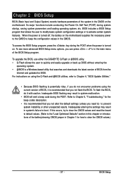
To upgrade the BIOS, use either the GIGABYTE Q-Flash or @BIOS utility. • Q-Flash allows the user to quickly and easily upgrade or back up BIOS without entering the operating system. • @BIOS is recommended that searches and downloads the latest version of BIOS, it with caution. To flash the BIOS, do not encounter problems using the Q-Flash...
To upgrade the BIOS, use either the GIGABYTE Q-Flash or @BIOS utility. • Q-Flash allows the user to quickly and easily upgrade or back up BIOS without entering the operating system. • @BIOS is recommended that searches and downloads the latest version of BIOS, it with caution. To flash the BIOS, do not encounter problems using the Q-Flash...
Manual
Page 38
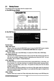
...GA-EX38T-DQ6 Motherboard - 38 - The POST Screen Motherboard Model BIOS Version Award Modular BIOS v6.00PG, An Energy Star Ally Copyright (C) 1984-2008, Award Software, Inc. You can be based on page 44. : BIOS Setup Press the key to enter BIOS Setup or to access the Q-Flash utility in BIOS... during the POST. To exit Boot Menu, press . The LOGO Screen (Default) :POST Screen :BIOS Setup/Q-Flash :XpressRecovery2 :Boot Menu :Qflash Function Keys B. EX38T-DQ6 F3b . . . . : BIOS Setup : XpressRecovery2 : Boot Menu : Qflash 02/04/2008-X38-ICH9-6A89OG0FC-00 Function Keys Function ...
...GA-EX38T-DQ6 Motherboard - 38 - The POST Screen Motherboard Model BIOS Version Award Modular BIOS v6.00PG, An Energy Star Ally Copyright (C) 1984-2008, Award Software, Inc. You can be based on page 44. : BIOS Setup Press the key to enter BIOS Setup or to access the Q-Flash utility in BIOS... during the POST. To exit Boot Menu, press . The LOGO Screen (Default) :POST Screen :BIOS Setup/Q-Flash :XpressRecovery2 :Boot Menu :Qflash Function Keys B. EX38T-DQ6 F3b . . . . : BIOS Setup : XpressRecovery2 : Boot Menu : Qflash 02/04/2008-X38-ICH9-6A89OG0FC-00 Function Keys Function ...
Manual
Page 39
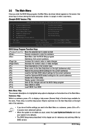
... to select an item Execute command or enter the submenu Main Menu: Exit the BIOS Setup program Submenus: Exit current submenu Increase the numeric value or make changes Decrease the...Help) of function keys available for the menu. Submenu Help While in a submenu, press to BIOS F12: Load CMOS from BIOS Main Menu Help The onscreen description of a highlighted setup option is displayed on the bottom line ...of the submenu. • If you do not find the settings you enter the BIOS Setup program, the Main Menu (as usual, select the Load Optimized Defaults item to set your system to...
... to select an item Execute command or enter the submenu Main Menu: Exit the BIOS Setup program Submenus: Exit current submenu Increase the numeric value or make changes Decrease the...Help) of function keys available for the menu. Submenu Help While in a submenu, press to BIOS F12: Load CMOS from BIOS Main Menu Help The onscreen description of a highlighted setup option is displayed on the bottom line ...of the submenu. • If you do not find the settings you enter the BIOS Setup program, the Main Menu (as usual, select the Load Optimized Defaults item to set your system to...
Manual
Page 40
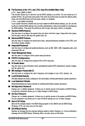
...Change, set , or disable password. First enter the profile name (to erase the default profile name, use this task.) GA-EX38T-DQ6 Motherboard - 40 - Pressing to the confirmation message will exit BIOS Setup. (Pressing can use the SPACE key) and then press to complete. ` F12 : Load CMOS from a profile created...and date, hard drive types, floppy disk drive types, and the type of errors that stop the system boot, etc. „ Advanced BIOS Features Use this menu to configure the device boot order, advanced features available on the CPU, and the primary display adapter. „ Integrated...
...Change, set , or disable password. First enter the profile name (to erase the default profile name, use this task.) GA-EX38T-DQ6 Motherboard - 40 - Pressing to the confirmation message will exit BIOS Setup. (Pressing can use the SPACE key) and then press to complete. ` F12 : Load CMOS from a profile created...and date, hard drive types, floppy disk drive types, and the type of errors that stop the system boot, etc. „ Advanced BIOS Features Use this menu to configure the device boot order, advanced features available on the CPU, and the primary display adapter. „ Integrated...

Manual
Page 41
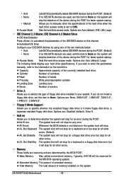
... arrow key to autodetect the parameters of the three methods below: - 41 - IDE Channel 0, 1 Master/Slave IDE HDD Auto-Detection Press to set the date. BIOS Setup 2-3 Standard CMOS Features Date (mm:dd:yy) Time (hh:mm:ss) CMOS Setup Utility-Copyright (C) 1984-2008 Award Software Standard CMOS Features Mon, Feb...
... arrow key to autodetect the parameters of the three methods below: - 41 - IDE Channel 0, 1 Master/Slave IDE HDD Auto-Detection Press to set the date. BIOS Setup 2-3 Standard CMOS Features Date (mm:dd:yy) Time (hh:mm:ss) CMOS Setup Utility-Copyright (C) 1984-2008 Award Software Standard CMOS Features Mon, Feb...
Manual
Page 42
...errors. (Default) The system boot will not stop for a floppy disk drive error but it will stop for the MS-DOS operating system. GA-EX38T-DQ6 Motherboard - 42 - Allows you do not install a floppy disk drive, set this item to the information on Allows you wish to enter ... devices are used , set this channel. Options are : Disabled (default), Drive A. Extended IDE Drive Configure your IDE/SATA devices by the BIOS POST. Options are used , set to manually enter the specifications of the device during the POST for all other errors. Cylinder Head Precomp Landing...
...errors. (Default) The system boot will not stop for a floppy disk drive error but it will stop for the MS-DOS operating system. GA-EX38T-DQ6 Motherboard - 42 - Allows you do not install a floppy disk drive, set this item to the information on Allows you wish to enter ... devices are used , set this channel. Options are : Disabled (default), Drive A. Extended IDE Drive Configure your IDE/SATA devices by the BIOS POST. Options are used , set to manually enter the specifications of the device during the POST for all other errors. Cylinder Head Precomp Landing...
Manual
Page 43
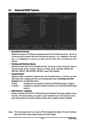
... are: Floppy, LS120, Hard Disk, CDROM, ZIP, USB-FDD, USB-ZIP, USB-CDROM, USB-HDD, Legacy LAN, Disabled. This feature allows your hard drive. BIOS Setup to 3 (Note) No-Execute Memory Protect (Note) CPU Enhanced Halt (C1E) (Note) CPU Thermal Monitor 2(TM2) (Note) CPU EIST Function (Note) Virtualization...down arrow key to select a device and press to exit this item, set the password(s) under the Set Supervisor/User Password item in the BIOS Main Menu. Password Check Specifies whether a password is required every time the system boots, or only when you install a CPU that supports this...
... are: Floppy, LS120, Hard Disk, CDROM, ZIP, USB-FDD, USB-ZIP, USB-CDROM, USB-HDD, Legacy LAN, Disabled. This feature allows your hard drive. BIOS Setup to 3 (Note) No-Execute Memory Protect (Note) CPU Enhanced Halt (C1E) (Note) CPU Thermal Monitor 2(TM2) (Note) CPU EIST Function (Note) Virtualization...down arrow key to select a device and press to exit this item, set the password(s) under the Set Supervisor/User Password item in the BIOS Main Menu. Password Check Specifies whether a password is required every time the system boots, or only when you install a CPU that supports this...
Manual
Page 45
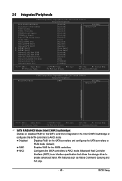
BIOS Setup Advanced Host Controller Interface (AHCI) is an interface specification that allows the storage driver to AHCI mode. AHCI Configures the SATA controllers to enable ...
BIOS Setup Advanced Host Controller Interface (AHCI) is an interface specification that allows the storage driver to AHCI mode. AHCI Configures the SATA controllers to enable ...
Manual
Page 47
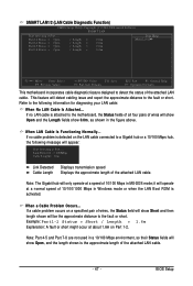
... is the approximate length of 10/100/1000 Mbps in the figure above. When a Cable Problem Occurs... This feature will appear: Start detecting at Port..... BIOS Setup Note: Part 4-5 and Part 7-8 are not used in a 10/100 Mbps environment, so their Status fields will only operate at a normal speed of the...
... is the approximate length of 10/100/1000 Mbps in the figure above. When a Cable Problem Occurs... This feature will appear: Start detecting at Port..... BIOS Setup Note: Part 4-5 and Part 7-8 are not used in a 10/100 Mbps environment, so their Status fields will only operate at a normal speed of the...
Manual
Page 49
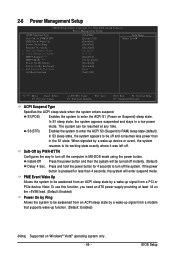
... the power button for less than in the S1 state. Note: To use this function, you need an ATX power supply providing at any time. BIOS Setup Enables the system to enter the ACPI S3 (Suspend to turn off instantly. (Default) Delay 4 Sec. If the power button is pressed for 4 seconds...
... the power button for less than in the S1 state. Note: To use this function, you need an ATX power supply providing at any time. BIOS Setup Enables the system to enter the ACPI S3 (Suspend to turn off instantly. (Default) Delay 4 Sec. If the power button is pressed for 4 seconds...


