Manual
Page 1
GA-EP45-DS3LR/ GA-EP45-DS3L LGA775 socket motherboard for Intel® CoreTM processor family/ Intel® Pentium® processor family/Intel® Celeron® processor family User's Manual Rev. 1005 12ME-EP45DS3L-1005R
GA-EP45-DS3LR/ GA-EP45-DS3L LGA775 socket motherboard for Intel® CoreTM processor family/ Intel® Pentium® processor family/Intel® Celeron® processor family User's Manual Rev. 1005 12ME-EP45DS3L-1005R

Manual
Page 2
Motherboard GA-EP45-DS3LR/GA-EP45-DS3L May 23, 2008 Motherboard GA-EP45-DS3LR/ GA-EP45-DS3L May 23, 2008
Motherboard GA-EP45-DS3LR/GA-EP45-DS3L May 23, 2008 Motherboard GA-EP45-DS3LR/ GA-EP45-DS3L May 23, 2008
Manual
Page 3
...2008 GIGA-BYTE TECHNOLOGY CO., LTD. No part of GIGABYTE branded motherboards. All rights reserved. sive global distributor of this manual is protected by copyright laws and is the property of the motherboard is 1.0. GIGABYTE UNITED INC. Disclaimer Information in this manual may be ...LTD as the exclu- is exclusively licensed to use GIGABYTE's unique features, read or download the information on/from the Support\Motherboard\Technology Guide page on your motherboard revision before updating motherboard BIOS, drivers, or when looking for technical information. ...
...2008 GIGA-BYTE TECHNOLOGY CO., LTD. No part of GIGABYTE branded motherboards. All rights reserved. sive global distributor of this manual is protected by copyright laws and is the property of the motherboard is 1.0. GIGABYTE UNITED INC. Disclaimer Information in this manual may be ...LTD as the exclu- is exclusively licensed to use GIGABYTE's unique features, read or download the information on/from the Support\Motherboard\Technology Guide page on your motherboard revision before updating motherboard BIOS, drivers, or when looking for technical information. ...
Manual
Page 4
Table of Contents Box Contents ...6 OptionalItems...6 GA-EP45-DS3LR/DS3L Motherboard Layout 7 Block Diagram...8 Chapter 1 Hardware Installation 9 1-1 Installation Precautions 9 1-2 Product Specifications 10 1-3 Installing the CPU and CPU Cooler 13 1-3-1 Installing the CPU 13 1-3-2 Installing the CPU ...
Table of Contents Box Contents ...6 OptionalItems...6 GA-EP45-DS3LR/DS3L Motherboard Layout 7 Block Diagram...8 Chapter 1 Hardware Installation 9 1-1 Installation Precautions 9 1-2 Product Specifications 10 1-3 Installing the CPU and CPU Cooler 13 1-3-1 Installing the CPU 13 1-3-2 Installing the CPU ...
Manual
Page 6
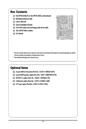
Box Contents GA-EP45-DS3LR or GA-EP45-DS3L motherboard Motherboard driver disk User's Manual Quick Installation Guide One IDE cable and one floppy disk drive cable Two SATA 3Gb/s cables I/O Shield • The box contents above are subject to change without notice. • The motherboard image is for reference only and the actual items shall depend on product...
Box Contents GA-EP45-DS3LR or GA-EP45-DS3L motherboard Motherboard driver disk User's Manual Quick Installation Guide One IDE cable and one floppy disk drive cable Two SATA 3Gb/s cables I/O Shield • The box contents above are subject to change without notice. • The motherboard image is for reference only and the actual items shall depend on product...
Manual
Page 7
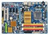
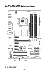
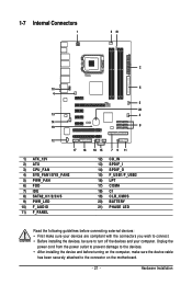
Only for GA-EP45-DS3LR. GA-EP45-DS3LR/DS3L Motherboard Layout KB_MS R_SPDIF R_USB_1 R_USB_2 R_USB_3 ATX_12V CPU_FAN PHASE LED ATX LGA775 DDR2_1 GA-EP45-DS3LR/DS3L DDR2_2 DDR2_3 DDR2_4 FDD SYS_FAN2 USB_LAN AUDIO Intel® P45 F_AUDIO SYS_FAN1 RTL8111C PCIEX1_1 PCIEX16 PCIEX1_2 PWR_FAN CODEC SPDIF_O CD_IN IT8718 SPDIF_I PCIEX1_3 PCIEX1_4 B_BIOS M_BIOS BATTERY PCI1 CLR_CMOS PCI2 CI Intel® ICH10R / Intel® ICH10 SATA2_3 SATA2_0 SATA2_4 SATA2_ 1 JMicron 368 IDE SATA2_5 SATA2_2 F_USB1 F_PANEL PWR_LED COMA LPT F_USB2 Only for GA-EP45-DS3L. - 7 -
Only for GA-EP45-DS3LR. GA-EP45-DS3LR/DS3L Motherboard Layout KB_MS R_SPDIF R_USB_1 R_USB_2 R_USB_3 ATX_12V CPU_FAN PHASE LED ATX LGA775 DDR2_1 GA-EP45-DS3LR/DS3L DDR2_2 DDR2_3 DDR2_4 FDD SYS_FAN2 USB_LAN AUDIO Intel® P45 F_AUDIO SYS_FAN1 RTL8111C PCIEX1_1 PCIEX16 PCIEX1_2 PWR_FAN CODEC SPDIF_O CD_IN IT8718 SPDIF_I PCIEX1_3 PCIEX1_4 B_BIOS M_BIOS BATTERY PCI1 CLR_CMOS PCI2 CI Intel® ICH10R / Intel® ICH10 SATA2_3 SATA2_0 SATA2_4 SATA2_ 1 JMicron 368 IDE SATA2_5 SATA2_2 F_USB1 F_PANEL PWR_LED COMA LPT F_USB2 Only for GA-EP45-DS3L. - 7 -
Manual
Page 9
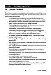
... are required for warranty validation. • Always remove the AC power by your dealer. Chapter 1 Hardware Installation 1-1 Installation Precautions The motherboard contains numerous delicate electronic circuits and components which can lead to damage to system components as well as physical harm to the user. •...wrist strap, keep your hands dry and first touch a metal object to eliminate static electricity. • Prior to installing the motherboard, please have it on top of an antistatic pad or within an electrostatic shielding container. • Before unplugging the power supply ...
... are required for warranty validation. • Always remove the AC power by your dealer. Chapter 1 Hardware Installation 1-1 Installation Precautions The motherboard contains numerous delicate electronic circuits and components which can lead to damage to system components as well as physical harm to the user. •...wrist strap, keep your hands dry and first touch a metal object to eliminate static electricity. • Prior to installing the motherboard, please have it on top of an antistatic pad or within an electrostatic shielding container. • Before unplugging the power supply ...

Manual
Page 10
...Intel® Pentium® Dual-Core processor/Intel® Celeron® processor in the LGA 775 package (Go to GIGABYTE's website for the latest CPU support list.) Š L2 cache varies with CPU Š 1600/1333/1066/800...1) Š Dual channel memory architecture Š Support for DDR2 1333/1200/1066/800/667 MHz memory modules (Go to GIGABYTE's website for the latest memory support list.) Š Realtek ALC888 codec Š High Definition Audio Š 2/4/5.1/7.1-channel ... the back panel, 4 via the USB brackets connected to 6 SATA 3Gb/s devices - GA-EP45-DS3LR/DS3L Motherboard - 10 -
...Intel® Pentium® Dual-Core processor/Intel® Celeron® processor in the LGA 775 package (Go to GIGABYTE's website for the latest CPU support list.) Š L2 cache varies with CPU Š 1600/1333/1066/800...1) Š Dual channel memory architecture Š Support for DDR2 1333/1200/1066/800/667 MHz memory modules (Go to GIGABYTE's website for the latest memory support list.) Š Realtek ALC888 codec Š High Definition Audio Š 2/4/5.1/7.1-channel ... the back panel, 4 via the USB brackets connected to 6 SATA 3Gb/s devices - GA-EP45-DS3LR/DS3L Motherboard - 10 -
Manual
Page 12
... CPU/System fan speed control function is supported will depend on the CPU/ System cooler you install. (Note 3) Available functions in EasyTune may differ by motherboard model. GA-EP45-DS3LR/DS3L Motherboard - 12 -
... CPU/System fan speed control function is supported will depend on the CPU/ System cooler you install. (Note 3) Available functions in EasyTune may differ by motherboard model. GA-EP45-DS3LR/DS3L Motherboard - 12 -
Manual
Page 13
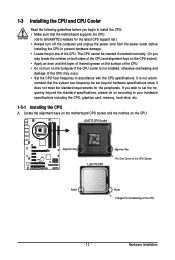
... CPU Socket Alignment Key LGA 775 CPU Alignment Key Pin One Corner of the CPU. mended that the motherboard supports the CPU. (Go to GIGABYTE's website for the peripherals. Locate the alignment keys on the motherboard CPU socket and the notches on the computer if the CPU cooler is not recom- 1-3 Installing the...
... CPU Socket Alignment Key LGA 775 CPU Alignment Key Pin One Corner of the CPU. mended that the motherboard supports the CPU. (Go to GIGABYTE's website for the peripherals. Locate the alignment keys on the motherboard CPU socket and the notches on the computer if the CPU cooler is not recom- 1-3 Installing the...

Manual
Page 14
... CPU socket. (DO NOT touch socket contacts.) Step 3: Remove the protective socket cover from the power outlet to prevent damage to the CPU. GA-EP45-DS3LR/DS3L Motherboard - 14 - CPU Socket Lever Step 1: Completely raise the CPU socket lever. Align the CPU pin one marking (triangle) with the pin one...may align the CPU notches with your thumb and index fingers. B. Before installing the CPU, make sure to correctly install the CPU into the motherboard CPU socket. Step 5: Once the CPU is not installed.) Step 4: Hold the CPU with the socket alignment keys) and gently insert the...
... CPU socket. (DO NOT touch socket contacts.) Step 3: Remove the protective socket cover from the power outlet to prevent damage to the CPU. GA-EP45-DS3LR/DS3L Motherboard - 14 - CPU Socket Lever Step 1: Completely raise the CPU socket lever. Align the CPU pin one marking (triangle) with the pin one...may align the CPU notches with your thumb and index fingers. B. Before installing the CPU, make sure to correctly install the CPU into the motherboard CPU socket. Step 5: Once the CPU is not installed.) Step 4: Hold the CPU with the socket alignment keys) and gently insert the...
Manual
Page 15
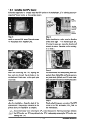
...You should hear a "click" when pushing down on the surface of the installed CPU. Step 6: Finally, attach the power connector of the motherboard. Inadequately removing the CPU cooler may adhere to install.) Step 3: Place the cooler atop the CPU, aligning the four push pins through the ... cooler.) Step 5: After the installation, check the back of the CPU cooler to your CPU cooler installation manual for instructions on the motherboard. Hardware Installation Push down each push pin. Use extreme care when removing the CPU cooler because the thermal grease/tape between the CPU cooler...
...You should hear a "click" when pushing down on the surface of the installed CPU. Step 6: Finally, attach the power connector of the motherboard. Inadequately removing the CPU cooler may adhere to install.) Step 3: Place the cooler atop the CPU, aligning the four push pins through the ... cooler.) Step 5: After the installation, check the back of the CPU cooler to your CPU cooler installation manual for instructions on the motherboard. Hardware Installation Push down each push pin. Use extreme care when removing the CPU cooler because the thermal grease/tape between the CPU cooler...
Manual
Page 16
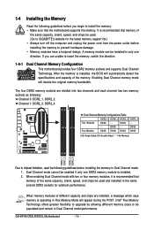
...motherboard provides four DDR2 memory sockets and supports Dual Channel Technology. DS/SS - - - - Dual Channel mode cannot be used . (Go to be installed in Dual Channel mode. 1. Intel® Flex Memory Technology offers greater flexibility to upgrade by allowing different memory sizes to GIGABYTE...DDR2_1, DDR2_2 Channel 1: DDR2_3, DDR2_4 Dual Channel Memory Configurations Table DDR2_1 DDR2_2 DDR2_3 DDR2_4 Two Modules DS/SS - - GA-EP45-DS3LR/DS3L Motherboard - 16 - After the memory is installed, the BIOS will double the original memory bandwidth. Enabling Dual Channel memory mode...
...motherboard provides four DDR2 memory sockets and supports Dual Channel Technology. DS/SS - - - - Dual Channel mode cannot be used . (Go to be installed in Dual Channel mode. 1. Intel® Flex Memory Technology offers greater flexibility to upgrade by allowing different memory sizes to GIGABYTE...DDR2_1, DDR2_2 Channel 1: DDR2_3, DDR2_4 Dual Channel Memory Configurations Table DDR2_1 DDR2_2 DDR2_3 DDR2_4 Two Modules DS/SS - - GA-EP45-DS3LR/DS3L Motherboard - 16 - After the memory is installed, the BIOS will double the original memory bandwidth. Enabling Dual Channel memory mode...
Manual
Page 17
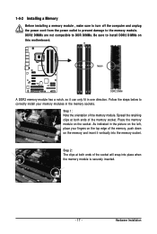
... to the memory module. As indicated in the picture on the left, place your memory modules in one direction. Place the memory module on this motherboard. Notch DDR2 DIMM A DDR2 memory module has a notch, so it vertically into place when the memory module is securely inserted. - 17 -
... to the memory module. As indicated in the picture on the left, place your memory modules in one direction. Place the memory module on this motherboard. Notch DDR2 DIMM A DDR2 memory module has a notch, so it vertically into place when the memory module is securely inserted. - 17 -
Manual
Page 18
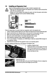
... off the computer and unplug the power cord from the power outlet before you begin to install an expansion card: • Make sure the motherboard supports the expansion card. Secure the card's metal bracket to make any required BIOS changes for your card. Turn on the card are completely ... at the end of the PCI Express x16 slot to release the card and then pull the card straight up from the chassis back panel. 2. GA-EP45-DS3LR/DS3L Motherboard - 18 - Remove the metal slot cover from the slot. Make sure the card is fully inserted into the slot. 4. Carefully read the manual...
... off the computer and unplug the power cord from the power outlet before you begin to install an expansion card: • Make sure the motherboard supports the expansion card. Secure the card's metal bracket to make any required BIOS changes for your card. Turn on the card are completely ... at the end of the PCI Express x16 slot to release the card and then pull the card straight up from the chassis back panel. 2. GA-EP45-DS3LR/DS3L Motherboard - 18 - Remove the metal slot cover from the slot. Make sure the card is fully inserted into the slot. 4. Carefully read the manual...
Manual
Page 19
... Connector This connector provides digital audio out to prevent an electrical short inside the cable connector. - 19 - Do not rock it straight out from the motherboard. • When removing the cable, pull it side to side to an external audio system that supports digital optical audio. Use this feature, ensure that...
... Connector This connector provides digital audio out to prevent an electrical short inside the cable connector. - 19 - Do not rock it straight out from the motherboard. • When removing the cable, pull it side to side to an external audio system that supports digital optical audio. Use this feature, ensure that...
Manual
Page 20
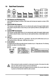
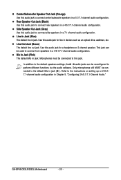
... to connect center/subwoofer speakers in devices such as an optical drive, walkman, etc. Line In Jack (Blue) The default line in a 4/5.1/7.1-channel audio configuration. GA-EP45-DS3LR/DS3L Motherboard - 20 - Side Speaker Out Jack (Gray) Use this jack. Microphones must be reconfigured to connect side speakers in jack. Mic In Jack (Pink) The...
... to connect center/subwoofer speakers in devices such as an optical drive, walkman, etc. Line In Jack (Blue) The default line in a 4/5.1/7.1-channel audio configuration. GA-EP45-DS3LR/DS3L Motherboard - 20 - Side Speaker Out Jack (Gray) Use this jack. Microphones must be reconfigured to connect side speakers in jack. Mic In Jack (Pink) The...
Manual
Page 21
..., make sure your devices are compliant with the connectors you wish to connect. • Before installing the devices, be sure to the connector on the motherboard. - 21 - Hardware Installation
..., make sure your devices are compliant with the connectors you wish to connect. • Before installing the devices, be sure to the connector on the motherboard. - 21 - Hardware Installation
Manual
Page 22
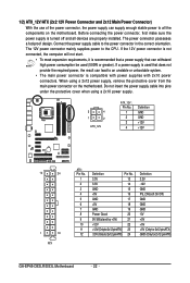
...3V -12V GND PS_ON(soft On/Off) GND GND GND -5V +5V +5V +5V (Only for 2x12-pinATX) GND (Only for 2x12-pin ATX) GA-EP45-DS3LR/DS3L Motherboard - 22 - The power connector possesses a foolproof design. Connect the power supply cable to the CPU. If the 12V power connector is not connected, the ...can supply enough stable power to an unstable or unbootable system. • The main power connector is turned off and all the components on the motherboard. Do not insert the power supply cable into pins under the protective cover when using a 2x12 power supply, remove the protective cover from the...
...3V -12V GND PS_ON(soft On/Off) GND GND GND -5V +5V +5V +5V (Only for 2x12-pinATX) GND (Only for 2x12-pin ATX) GA-EP45-DS3LR/DS3L Motherboard - 22 - The power connector possesses a foolproof design. Connect the power supply cable to the CPU. If the 12V power connector is not connected, the ...can supply enough stable power to an unstable or unbootable system. • The main power connector is turned off and all the components on the motherboard. Do not insert the power supply cable into pins under the protective cover when using a 2x12 power supply, remove the protective cover from the...
Manual
Page 23
The types of a CPU fan with fan speed control design. 3/4/5) CPU_FAN/SYS_FAN1/SYS_FAN2/PWR_FAN (Fan Headers) The motherboard has a 4-pin CPU fan header (CPU_FAN), a 3-pin (SYS_FAN1) and a 4-pin (SYS_FAN2) system fan headers, and a 3-pin power fan header... +12V Sense 4 Speed Control 1 SYS_FAN2 SYS_FAN2: Pin No. 1 2 3 Definition GND Speed Control Sense 4 +5V 1 SYS_FAN1 / PWR_FAN SYS_FAN1/PWR_FAN: Pin No. The motherboard supports CPU fan speed control, which requires the use of floppy disk drives supported are not configuration jumper blocks. Overheating may hang. • These fan...
The types of a CPU fan with fan speed control design. 3/4/5) CPU_FAN/SYS_FAN1/SYS_FAN2/PWR_FAN (Fan Headers) The motherboard has a 4-pin CPU fan header (CPU_FAN), a 3-pin (SYS_FAN1) and a 4-pin (SYS_FAN2) system fan headers, and a 3-pin power fan header... +12V Sense 4 Speed Control 1 SYS_FAN2 SYS_FAN2: Pin No. 1 2 3 Definition GND Speed Control Sense 4 +5V 1 SYS_FAN1 / PWR_FAN SYS_FAN1/PWR_FAN: Pin No. The motherboard supports CPU fan speed control, which requires the use of floppy disk drives supported are not configuration jumper blocks. Overheating may hang. • These fan...


