Manual
Page 4
... Box Contents ...6 OptionalItems...6 GA-EP45-DS3LR/DS3L Motherboard Layout 7 Block Diagram...8 Chapter 1 Hardware Installation 9 1-1 Installation Precautions 9 1-2 Product Specifications 10 1-3 Installing the CPU and CPU Cooler 13 1-3-1 Installing the CPU 13 1-3-2 Installing the CPU Cooler 15 1-4 Installing the Memory 16 1-4-1 Dual Channel Memory Configuration 16 1-4-2 Installing a Memory 17 1-5 Installing an Expansion Card 18 1-6 Back Panel Connectors 19 1-7 Internal Connectors 21 Chapter 2 BIOS Setup 33 2-1 Startup Screen 34 2-2 The Main Menu 35 2-3 MB Intelligent Tweaker...
... Box Contents ...6 OptionalItems...6 GA-EP45-DS3LR/DS3L Motherboard Layout 7 Block Diagram...8 Chapter 1 Hardware Installation 9 1-1 Installation Precautions 9 1-2 Product Specifications 10 1-3 Installing the CPU and CPU Cooler 13 1-3-1 Installing the CPU 13 1-3-2 Installing the CPU Cooler 15 1-4 Installing the Memory 16 1-4-1 Dual Channel Memory Configuration 16 1-4-2 Installing a Memory 17 1-5 Installing an Expansion Card 18 1-6 Back Panel Connectors 19 1-7 Internal Connectors 21 Chapter 2 BIOS Setup 33 2-1 Startup Screen 34 2-2 The Main Menu 35 2-3 MB Intelligent Tweaker...

Manual
Page 5
... Utility 68 4-2-2 Updating the BIOS with the @BIOS Utility 71 4-3 EasyTune 6 ...72 4-4 Dynamic Energy Saver Advanced 73 4-5 Q-Share ...75 4-6 Time Repair ...76 Chapter 5 Appendix ...77 5-1 Configuring SATA Hard Drive(s 77 5-1-1 Configuring the Onboard SATA Controller 77 5-1-2 Making a SATA RAID/AHCI Driver Diskette 83 5-1-3 Installing the SATA RAID/AHCI Driver and Operating System 85 5-2 Configuring Audio Input and Output 90 5-2-1 Configuring 2/4/5.1/7.1-Channel Audio 90 5-2-2 Installing the S/PDIF In Cable (Optional 92 5-2-3 Configuring Microphone Recording 94 5-2-4 Using the Sound...
... Utility 68 4-2-2 Updating the BIOS with the @BIOS Utility 71 4-3 EasyTune 6 ...72 4-4 Dynamic Energy Saver Advanced 73 4-5 Q-Share ...75 4-6 Time Repair ...76 Chapter 5 Appendix ...77 5-1 Configuring SATA Hard Drive(s 77 5-1-1 Configuring the Onboard SATA Controller 77 5-1-2 Making a SATA RAID/AHCI Driver Diskette 83 5-1-3 Installing the SATA RAID/AHCI Driver and Operating System 85 5-2 Configuring Audio Input and Output 90 5-2-1 Configuring 2/4/5.1/7.1-Channel Audio 90 5-2-2 Installing the S/PDIF In Cable (Optional 92 5-2-3 Configuring Microphone Recording 94 5-2-4 Using the Sound...

Manual
Page 10
Support for SATA RAID 0, RAID 1, RAID 5 and RAID 10 Š JMicron 368 chip: - 1 x IDE connector supporting ATA-133/100/66/33 and up to 2 IDE devices Š iTE IT8718 chip: - 1 x floppy disk drive connector supporting up to the internal USB headers) Only for GA-EP45-DS3LR. Only for GA-EP45-DS3L. 1-2 Product Specifications CPU Front Side Bus Chipset Memory Audio LAN Expansion Slots Storage Interface USB Š Support for an Intel® CoreTM 2 Extreme processor/ Intel® CoreTM 2 Quad processor/Intel® CoreTM 2 Duo processor/ Intel® Pentium® Dual-Core processor/...
Support for SATA RAID 0, RAID 1, RAID 5 and RAID 10 Š JMicron 368 chip: - 1 x IDE connector supporting ATA-133/100/66/33 and up to 2 IDE devices Š iTE IT8718 chip: - 1 x floppy disk drive connector supporting up to the internal USB headers) Only for GA-EP45-DS3LR. Only for GA-EP45-DS3L. 1-2 Product Specifications CPU Front Side Bus Chipset Memory Audio LAN Expansion Slots Storage Interface USB Š Support for an Intel® CoreTM 2 Extreme processor/ Intel® CoreTM 2 Quad processor/Intel® CoreTM 2 Duo processor/ Intel® Pentium® Dual-Core processor/...
Manual
Page 16
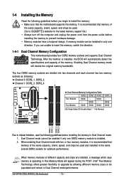
.... GA-EP45-DS3LR/DS3L Motherboard - 16 - A memory module can be populated and remain in Flex Memory Mode will appear during the POST. DS/SS - - - - Intel® Flex Memory Technology offers greater flexibility to upgrade by allowing different memory sizes to prevent hardware damage. • Memory modules have a foolproof design. When memory modules of the same capacity, brand, speed, and chips be enabled if only one direction. Dual Channel mode cannot be used...
.... GA-EP45-DS3LR/DS3L Motherboard - 16 - A memory module can be populated and remain in Flex Memory Mode will appear during the POST. DS/SS - - - - Intel® Flex Memory Technology offers greater flexibility to upgrade by allowing different memory sizes to prevent hardware damage. • Memory modules have a foolproof design. When memory modules of the same capacity, brand, speed, and chips be enabled if only one direction. Dual Channel mode cannot be used...
Manual
Page 18
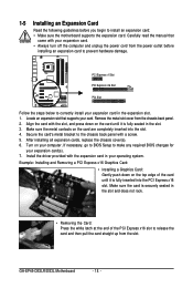
... installing all expansion cards, replace the chassis cover(s). 6. Carefully read the manual that supports your card. If necessary, go to BIOS Setup to make any required BIOS changes for your computer. Remove the metal slot cover from the slot. Secure the card's metal bracket to the chassis back panel with your operating system. Turn on the card until it is fully seated in the slot and does not rock. • Removing...
... installing all expansion cards, replace the chassis cover(s). 6. Carefully read the manual that supports your card. If necessary, go to BIOS Setup to make any required BIOS changes for your computer. Remove the metal slot cover from the slot. Secure the card's metal bracket to the chassis back panel with your operating system. Turn on the card until it is fully seated in the slot and does not rock. • Removing...

Manual
Page 31
... unplug the power cord from the jumper. Failure to do so may cause damage to the motherboard. • After system restart, go to BIOS Setup to load factory defaults (select Load Optimized Defaults) or manually configure the BIOS settings (refer to remove the jumper cap from the power outlet before clearing the CMOS values. • After clearing the CMOS values and before turning on the two pins to temporarily short the two pins or use a metal...
... unplug the power cord from the jumper. Failure to do so may cause damage to the motherboard. • After system restart, go to BIOS Setup to load factory defaults (select Load Optimized Defaults) or manually configure the BIOS settings (refer to remove the jumper cap from the power outlet before clearing the CMOS values. • After clearing the CMOS values and before turning on the two pins to temporarily short the two pins or use a metal...
Manual
Page 36
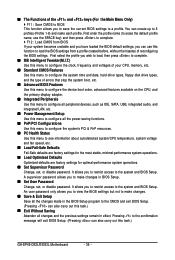
... CPU, memory, etc. „ Standard CMOS Features Use this menu to configure the system time and date, hard drive types, floppy disk drive types, and the type of errors that stop the system boot, etc. „ Advanced BIOS Features Use this menu to configure the device boot order, advanced features available on the CPU, and the primary display adapter. „ Integrated Peripherals Use this menu to configure all peripheral devices, such as IDE, SATA, USB, integrated audio, and integrated LAN, etc. „ Power Management Setup Use...
... CPU, memory, etc. „ Standard CMOS Features Use this menu to configure the system time and date, hard drive types, floppy disk drive types, and the type of errors that stop the system boot, etc. „ Advanced BIOS Features Use this menu to configure the device boot order, advanced features available on the CPU, and the primary display adapter. „ Integrated Peripherals Use this menu to configure all peripheral devices, such as IDE, SATA, USB, integrated audio, and integrated LAN, etc. „ Power Management Setup Use...
Manual
Page 38
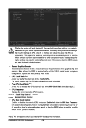
... install a CPU that supports this occurs, clear the CMOS values and reset the board to default values.) Robust Graphics Booster Robust Graphics Booster (R.G.B.) helps to increase the CPU clock ratio set the R.G.B. GA-EP45-DS3LR/DS3L Motherboard - 38 - Incorrectly doing overclock/overvoltage may result in the CPU Clock Ratio item above by 0.5. Fine CPU Clock Ratio (Note) Allows you to enhance the performance of CPU host clock. This page is installed. MCH Core MCH Reference ICH I/O >>> DRAM DRAM Voltage CMOS Setup Utility...
... install a CPU that supports this occurs, clear the CMOS values and reset the board to default values.) Robust Graphics Booster Robust Graphics Booster (R.G.B.) helps to increase the CPU clock ratio set the R.G.B. GA-EP45-DS3LR/DS3L Motherboard - 38 - Incorrectly doing overclock/overvoltage may result in the CPU Clock Ratio item above by 0.5. Fine CPU Clock Ratio (Note) Allows you to enhance the performance of CPU host clock. This page is installed. MCH Core MCH Reference ICH I/O >>> DRAM DRAM Voltage CMOS Setup Utility...

Manual
Page 46
... accept. Options are: Floppy, LS120, Hard Disk, CDROM, ZIP, USB-FDD, USB-ZIP, USB-CDROM, USB-HDD, Legacy LAN, Disabled. Setup System A password is only required for entering the BIOS Setup program. (Default) A password is required every time the system boots, or only when you install a CPU that supports this item, set the password(s) under the Set Supervisor/User Password item in the BIOS Main Menu. Capability Enables or disables the S.M.A.R.T. (Self Monitoring and Reporting Technology) capability of the hard drive and to report read/write errors of...
... accept. Options are: Floppy, LS120, Hard Disk, CDROM, ZIP, USB-FDD, USB-ZIP, USB-CDROM, USB-HDD, Legacy LAN, Disabled. Setup System A password is only required for entering the BIOS Setup program. (Default) A password is required every time the system boots, or only when you install a CPU that supports this item, set the password(s) under the Set Supervisor/User Password item in the BIOS Main Menu. Capability Enables or disables the S.M.A.R.T. (Self Monitoring and Reporting Technology) capability of the hard drive and to report read/write errors of...
Manual
Page 49
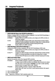
... hot plug. BIOS Setup Disabled Disables RAID for the SATA controllers integrated in Native IDE mode. 2-6 Integrated Peripherals CMOS Setup Utility-Copyright (C) 1984-2008 Award Software Integrated Peripherals SATA RAID/AHCI Mode 1 SATA AHCI Mode 2 SATA Port0-3 Native Mode USB Controller USB 2.0 Controller USB Keyboard Support USB Mouse Support Legacy USB storage detect Azalia Codec Onboard H/W LAN Green LAN ` SMART LAN Onboard LAN Boot ROM Onboard IDE Controller Onboard Serial Port 1 Onboard Parallel Port Parallel Port Mode [Disabled] [Disabled] [Disabled] [Enabled] [Enabled] [Disabled...
... hot plug. BIOS Setup Disabled Disables RAID for the SATA controllers integrated in Native IDE mode. 2-6 Integrated Peripherals CMOS Setup Utility-Copyright (C) 1984-2008 Award Software Integrated Peripherals SATA RAID/AHCI Mode 1 SATA AHCI Mode 2 SATA Port0-3 Native Mode USB Controller USB 2.0 Controller USB Keyboard Support USB Mouse Support Legacy USB storage detect Azalia Codec Onboard H/W LAN Green LAN ` SMART LAN Onboard LAN Boot ROM Onboard IDE Controller Onboard Serial Port 1 Onboard Parallel Port Parallel Port Mode [Disabled] [Disabled] [Disabled] [Enabled] [Enabled] [Disabled...
Manual
Page 51
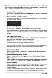
... 368 chip. (Default: Enabled) Onboard Serial Port 1 Enables or disables the first serial port and specifies its base I /O address and corresponding interrupt. If a cable problem occurs on the LAN cable connected to activate the boot ROM integrated with the onboard LAN chip. (Default: Disabled) Onboard IDE Controller (JMicron 368 Chip) Enables or disables the IDE controller integrated in MS-DOS mode; Onboard LAN Boot ROM Allows you to decide whether to a Gigabit hub or a 10/100 Mbps hub, the following information for the onboard parallel (LPT) port. Options...
... 368 chip. (Default: Enabled) Onboard Serial Port 1 Enables or disables the first serial port and specifies its base I /O address and corresponding interrupt. If a cable problem occurs on the LAN cable connected to activate the boot ROM integrated with the onboard LAN chip. (Default: Disabled) Onboard IDE Controller (JMicron 368 Chip) Enables or disables the IDE controller integrated in MS-DOS mode; Onboard LAN Boot ROM Allows you to decide whether to a Gigabit hub or a 10/100 Mbps hub, the following information for the onboard parallel (LPT) port. Options...
Manual
Page 55
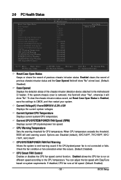
... the motherboard CI header. To clear the chassis intrusion status record, set Reset Case Open Status to Enabled, save the settings to emit warning sound if the CPU/system/power fan is removed, this occurs. (Default: Disabled) CPU Smart FAN Control Enables or disables the CPU fan speed control function. Check the fan condition or fan connection when this field will show "Yes", otherwise it will show "No" at next boot. (Default: Disabled) Case Opened Displays the detection status of previous chassis intrusion status. If disabled, CPU fan...
... the motherboard CI header. To clear the chassis intrusion status record, set Reset Case Open Status to Enabled, save the settings to emit warning sound if the CPU/system/power fan is removed, this occurs. (Default: Disabled) CPU Smart FAN Control Enables or disables the CPU fan speed control function. Check the fan condition or fan connection when this field will show "Yes", otherwise it will show "No" at next boot. (Default: Disabled) Case Opened Displays the detection status of previous chassis intrusion status. If disabled, CPU fan...
Manual
Page 68
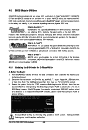
... POST, press the key to access Q-Flash. 4-2 BIOS Update Utilities GIGABYTE motherboards provide two unique BIOS update tools, Q-FlashTM and @BIOSTM. Additionally, this motherboard features the DualBIOSTM design, which enhances protection for the safety and stability of system safety, users cannot update the backup BIOS manually. Normally, the system works on the next system boot and copy the BIOS file to the main BIOS to enter MSDOS mode. Before You Begin: 1. EP45-DS3L E12c . . . . : BIOS Setup : XpressRecovery2 : Boot Menu...
... POST, press the key to access Q-Flash. 4-2 BIOS Update Utilities GIGABYTE motherboards provide two unique BIOS update tools, Q-FlashTM and @BIOSTM. Additionally, this motherboard features the DualBIOSTM design, which enhances protection for the safety and stability of system safety, users cannot update the backup BIOS manually. Normally, the system works on the next system boot and copy the BIOS file to the main BIOS to enter MSDOS mode. Before You Begin: 1. EP45-DS3L E12c . . . . : BIOS Setup : XpressRecovery2 : Boot Menu...
Manual
Page 69
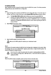
... supports USB flash drive or hard drives using FAT32/16/12 file system. • If the BIOS update file is saved to a hard drive in RAID/AHCI mode or a hard drive attached to an independent IDE/SATA controller, use the up or down arrow key to a floppy disk. Unique Features In the main menu of the system reading the BIOS file from the floppy disk is complete, press any keEyStCo:Rcoensettinue F10:Power Off - 69 - Make sure the BIOS update file matches your motherboard model. The monitor will display...
... supports USB flash drive or hard drives using FAT32/16/12 file system. • If the BIOS update file is saved to a hard drive in RAID/AHCI mode or a hard drive attached to an independent IDE/SATA controller, use the up or down arrow key to a floppy disk. Unique Features In the main menu of the system reading the BIOS file from the floppy disk is complete, press any keEyStCo:Rcoensettinue F10:Power Off - 69 - Make sure the BIOS update file matches your motherboard model. The monitor will display...
Manual
Page 72
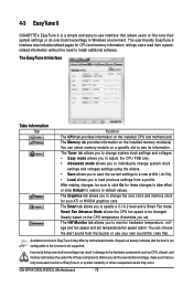
... mode allows you to individually change the core clock and memory clock for CPU and memory information, lettings users read their system settings or do overclock/overvoltage in damage to default values. The Smart tab allows you to specify a C.I.A.2 level and a Smart Fan mode. The HW Monitor tab allows you to monitor hardware temperature, voltage and fan speed and set . The EasyTune 6 Interface Tabs Information Tab Function The CPU tab provides information on the installed memory...
... mode allows you to individually change the core clock and memory clock for CPU and memory information, lettings users read their system settings or do overclock/overvoltage in damage to default values. The Smart tab allows you to specify a C.I.A.2 level and a Smart Fan mode. The HW Monitor tab allows you to monitor hardware temperature, voltage and fan speed and set . The EasyTune 6 Interface Tabs Information Tab Function The CPU tab provides information on the installed memory...

Manual
Page 77
... the motherboard. Then connect the power connector from your computer. Appendix Configure a RAID array in BIOS Setup. Installing SATA hard drive(s) in your power supply to an available SATA port on the SATA controller. (Note 2) Required when the SATA controller is set to ensure optimal performance, it is recommended that you begin Please prepare: • At least two SATA hard drives (to AHCI or RAID mode. - 77 - Chapter 5 Appendix 5-1 Configuring SATA Hard Drive(s) To configure SATA hard drive(s), follow the steps below: A. Make a floppy disk containing the SATA RAID/AHCI driver...
... the motherboard. Then connect the power connector from your computer. Appendix Configure a RAID array in BIOS Setup. Installing SATA hard drive(s) in your power supply to an available SATA port on the SATA controller. (Note 2) Required when the SATA controller is set to ensure optimal performance, it is recommended that you begin Please prepare: • At least two SATA hard drives (to AHCI or RAID mode. - 77 - Chapter 5 Appendix 5-1 Configuring SATA Hard Drive(s) To configure SATA hard drive(s), follow the steps below: A. Make a floppy disk containing the SATA RAID/AHCI driver...
Manual
Page 78
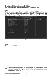
... RAID, set SATA RAID/AHCI Mode under the Integrated Peripherals menu to configure the SATA controller mode correctly in this item to enter BIOS Setup during the POST (Power-On Self-Test). CMOS Setup Utility-Copyright (C) 1984-2008 Award Software Integrated Peripherals SATA RAID/AHCI Mode SATA Port0-3 Native Mode USB Controller USB 2.0 Controller USB Keyboard Support USB Mouse Support Legacy USB storage detect Azalia Codec Onboard H/W LAN Green LAN ` SMART LAN Onboard LAN Boot ROM Onboard IDE Controller Onboard Serial Port 1 Onboard Parallel Port Parallel Port Mode [Disabled] [Disabled...
... RAID, set SATA RAID/AHCI Mode under the Integrated Peripherals menu to configure the SATA controller mode correctly in this item to enter BIOS Setup during the POST (Power-On Self-Test). CMOS Setup Utility-Copyright (C) 1984-2008 Award Software Integrated Peripherals SATA RAID/AHCI Mode SATA Port0-3 Native Mode USB Controller USB 2.0 Controller USB Keyboard Support USB Mouse Support Legacy USB storage detect Azalia Codec Onboard H/W LAN Green LAN ` SMART LAN Onboard LAN Boot ROM Onboard IDE Controller Onboard Serial Port 1 Onboard Parallel Port Parallel Port Mode [Disabled] [Disabled...

Manual
Page 83
... disk and motherboard driver disk in MS-DOS mode(Note). Boot from the motherboard driver disk to a floppy disk. A command prompt window will then automatically zip and transfer this driver file to the floppy disk. For installing Windows Vista, you need to install the SATA controller driver during the Windows setup process. Once at the A:\> prompt, change to exit when finished. Press after each command (Figure 1): cd bootdrv menu Step 2: When the controller menu (Figure 2) appears, remove the startup disk...
... disk and motherboard driver disk in MS-DOS mode(Note). Boot from the motherboard driver disk to a floppy disk. A command prompt window will then automatically zip and transfer this driver file to the floppy disk. For installing Windows Vista, you need to install the SATA controller driver during the Windows setup process. Once at the A:\> prompt, change to exit when finished. Press after each command (Figure 1): cd bootdrv menu Step 2: When the controller menu (Figure 2) appears, remove the startup disk...

Manual
Page 85
... boot from the Windows XP setup disk and press as soon as you see the next screen. Appendix 5-1-3 Installing the SATA RAID/AHCI Driver and Operating System Now that below appears, insert the floppy disk containing the SATA RAID/AHCI driver and press (Figure 2). The following mass storage devices(s) * To specify additional SCSI adapters, CD-ROM drives, or special disk controllers for use with Windows, including those for use with Windows, press ENTER. Installing Windows XP Step 1: Restart your hard drive(s). Windows Setup...
... boot from the Windows XP setup disk and press as soon as you see the next screen. Appendix 5-1-3 Installing the SATA RAID/AHCI Driver and Operating System Now that below appears, insert the floppy disk containing the SATA RAID/AHCI driver and press (Figure 2). The following mass storage devices(s) * To specify additional SCSI adapters, CD-ROM drives, or special disk controllers for use with Windows, including those for use with Windows, press ENTER. Installing Windows XP Step 1: Restart your hard drive(s). Windows Setup...
Manual
Page 97
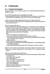
... the battery holder and wait for one minute. Press to the maximum volume? Q:Why do I still get a weak sound even though I clear the CMOS values? A: The following Award BIOS beep code descriptions may help you identify possible computer problems. (For reference only.) 1 short: System boots successfully 2 short: CMOS setting error 1 long, 1 short: Memory or motherboard error 1 long, 2 short: Monitor or graphics card error 1 long, 3 short: Keyboard error 1 long, 9 short: BIOS ROM error Continuous long beeps: Graphics card not inserted properly Continuous short beeps: Power error - 97...
... the battery holder and wait for one minute. Press to the maximum volume? Q:Why do I still get a weak sound even though I clear the CMOS values? A: The following Award BIOS beep code descriptions may help you identify possible computer problems. (For reference only.) 1 short: System boots successfully 2 short: CMOS setting error 1 long, 1 short: Memory or motherboard error 1 long, 2 short: Monitor or graphics card error 1 long, 3 short: Keyboard error 1 long, 9 short: BIOS ROM error Continuous long beeps: Graphics card not inserted properly Continuous short beeps: Power error - 97...


