
Manual
Page 1
GA-EP41T-USB3 LGA775 socket motherboard for Intel® Core™ processor family/ Intel® Pentium® processor family/Intel® Celeron® processor family User's Manual Rev. 1001 12ME-41TUSB3-1001R
GA-EP41T-USB3 LGA775 socket motherboard for Intel® Core™ processor family/ Intel® Pentium® processor family/Intel® Celeron® processor family User's Manual Rev. 1001 12ME-41TUSB3-1001R

Manual
Page 2
Motherboard GA-EP41T-USB3 Jan. 4, 2010 Motherboard GA-EP41T-USB3 Jan. 4, 2010
Motherboard GA-EP41T-USB3 Jan. 4, 2010 Motherboard GA-EP41T-USB3 Jan. 4, 2010

Manual
Page 3
...Disclaimer Information in this manual are legally registered to assist in this manual is protected by GIGABYTE without GIGABYTE's prior written permission. Check your motherboard looks like this manual may be made by copyright laws and is 1.0. The trademarks mentioned in ...the use GIGABYTE's unique features, read or download the information on/from the Support&Downloads\Motherboard\Technology Guide page on your motherboard revision before updating motherboard BIOS, drivers, or when looking for technical information. ...
...Disclaimer Information in this manual are legally registered to assist in this manual is protected by GIGABYTE without GIGABYTE's prior written permission. Check your motherboard looks like this manual may be made by copyright laws and is 1.0. The trademarks mentioned in ...the use GIGABYTE's unique features, read or download the information on/from the Support&Downloads\Motherboard\Technology Guide page on your motherboard revision before updating motherboard BIOS, drivers, or when looking for technical information. ...

Manual
Page 4
Table of Contents Box Contents...6 Optional Items...6 GA-EP41T-USB3 Motherboard Layout 7 GA-EP41T-USB3 Motherboard Block Diagram 8 Chapter 1 Hardware Installation 9 1-1 Installation Precautions 9 1-2 Product Specifications 10 1-3 Installing the CPU and CPU Cooler 13 1-3-1 Installing the CPU 13 1-3-2 Installing the CPU Cooler ...
Table of Contents Box Contents...6 Optional Items...6 GA-EP41T-USB3 Motherboard Layout 7 GA-EP41T-USB3 Motherboard Block Diagram 8 Chapter 1 Hardware Installation 9 1-1 Installation Precautions 9 1-2 Product Specifications 10 1-3 Installing the CPU and CPU Cooler 13 1-3-1 Installing the CPU 13 1-3-2 Installing the CPU Cooler ...

Manual
Page 6
Box Contents GA-EP41T-USB3 motherboard Motherboard driver disk User's Manual Quick Installation Guide One IDE cable Two SATA 3Gb/s cables I/O Shield • The box contents above are subject to change without notice. • The motherboard image is for reference only and the actual items shall depend on the product package you obtain. The box contents are...
Box Contents GA-EP41T-USB3 motherboard Motherboard driver disk User's Manual Quick Installation Guide One IDE cable Two SATA 3Gb/s cables I/O Shield • The box contents above are subject to change without notice. • The motherboard image is for reference only and the actual items shall depend on the product package you obtain. The box contents are...

Manual
Page 7
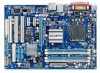
GA-EP41T-USB3 Motherboard Layout LPT KB_MS Coaxial Optical ATX_12V LGA775 PHASE LED CPU_FAN PWR_FAN COMA R_USB30 LAN USB NEC F_AUDIO D720200F1 AUDIO RTL8111D SYS_FAN1 PCIEX16 PCIEX1_1 CODEC PCIEX1_2 SPDIF_O CD_IN PCI1 SPDIF_I PCI2 IT8718 PCI3 FDD DDR3_1 DDR3_2 DDR3_3 DDR3_4 Intel® G41 ATX GA-EP41T-USB3 CLR_CMOS BAT Intel® ICH7 SATA2_0 SATA2_2 SYS_FAN2 SATA2_1 SATA2_3 IDE B_BIOS M_BIOS F_PANEL F_USB1 F_USB2 - 7 -
GA-EP41T-USB3 Motherboard Layout LPT KB_MS Coaxial Optical ATX_12V LGA775 PHASE LED CPU_FAN PWR_FAN COMA R_USB30 LAN USB NEC F_AUDIO D720200F1 AUDIO RTL8111D SYS_FAN1 PCIEX16 PCIEX1_1 CODEC PCIEX1_2 SPDIF_O CD_IN PCI1 SPDIF_I PCI2 IT8718 PCI3 FDD DDR3_1 DDR3_2 DDR3_3 DDR3_4 Intel® G41 ATX GA-EP41T-USB3 CLR_CMOS BAT Intel® ICH7 SATA2_0 SATA2_2 SYS_FAN2 SATA2_1 SATA2_3 IDE B_BIOS M_BIOS F_PANEL F_USB1 F_USB2 - 7 -

Manual
Page 8
GA-EP41T-USB3 Motherboard Block Diagram PCIe CLK (100 MHz) LGA775 CPU CPU CLK+/(333/266/200 MHz) 1 PCI Express x16 PCI Express x16 2 USB 3.0 NEC D720200F1 x1 PCI ...
GA-EP41T-USB3 Motherboard Block Diagram PCIe CLK (100 MHz) LGA775 CPU CPU CLK+/(333/266/200 MHz) 1 PCI Express x16 PCI Express x16 2 USB 3.0 NEC D720200F1 x1 PCI ...

Manual
Page 9
...an electrostatic discharge (ESD) wrist strap when handling electronic com- These stickers are connected tightly and securely. • When handling the motherboard, avoid touching any installation steps or have it on top of an antistatic pad or within an electrostatic shielding container. • ... manual and follow these procedures: • Prior to installation, do not remove or break motherboard S/N (Serial Number) sticker or warranty sticker provided by unplugging the power cord from the motherboard, make sure the power supply has been turned off. • Before turning on the ...
...an electrostatic discharge (ESD) wrist strap when handling electronic com- These stickers are connected tightly and securely. • When handling the motherboard, avoid touching any installation steps or have it on top of an antistatic pad or within an electrostatic shielding container. • ... manual and follow these procedures: • Prior to installation, do not remove or break motherboard S/N (Serial Number) sticker or warranty sticker provided by unplugging the power cord from the motherboard, make sure the power supply has been turned off. • Before turning on the ...
Manual
Page 12
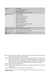
to GIGABYTE's website for the latest memory support list.) (Note 3) Two share the same ports with USB 3.0. (Note 4) Whether the CPU/system fan speed control function is to be installed, we suggest that you install. (Note 5) Available functions in EasyTune may differ by motherboard model. Hardware Installation - 12 - BIOS w w w w Unique Features w w w w w w w w w w Bundled Software...
to GIGABYTE's website for the latest memory support list.) (Note 3) Two share the same ports with USB 3.0. (Note 4) Whether the CPU/system fan speed control function is to be installed, we suggest that you install. (Note 5) Available functions in EasyTune may differ by motherboard model. Hardware Installation - 12 - BIOS w w w w Unique Features w w w w w w w w w w Bundled Software...

Manual
Page 13
... according to your hardware specifications including the CPU, graphics card, memory, hard drive, etc. 1-3-1 Installing the CPU A. Locate the alignment keys on the motherboard CPU socket and the notches on the CPU - 13 - The CPU cannot be set the frequency beyond hardware specifications since it does not meet the... CPU. 1-3 Installing the CPU and CPU Cooler Read the following guidelines before you begin to install the CPU: • Make sure that the motherboard supports the CPU. (Go to GIGABYTE's website for the peripherals. It is not installed, otherwise overheating and dam-
... according to your hardware specifications including the CPU, graphics card, memory, hard drive, etc. 1-3-1 Installing the CPU A. Locate the alignment keys on the motherboard CPU socket and the notches on the CPU - 13 - The CPU cannot be set the frequency beyond hardware specifications since it does not meet the... CPU. 1-3 Installing the CPU and CPU Cooler Read the following guidelines before you begin to install the CPU: • Make sure that the motherboard supports the CPU. (Go to GIGABYTE's website for the peripherals. It is not installed, otherwise overheating and dam-

Manual
Page 14
... index fingers. Step 5: Once the CPU is not installed.) Step 4: Hold the CPU with the socket alignment keys) and gently insert the CPU into the motherboard CPU socket.
... index fingers. Step 5: Once the CPU is not installed.) Step 4: Hold the CPU with the socket alignment keys) and gently insert the CPU into the motherboard CPU socket.

Manual
Page 15
...the installation, check the back of the installed CPU. 1-3-2 Installing the CPU Cooler Follow the steps below to correctly install the CPU cooler on the motherboard. (The following procedure uses Intel® boxed cooler as the picture above shows, the installation is to install.) Step 3: Place the cooler atop the... CPU, aligning the four push pins through the pin holes on the motherboard. Direction of the Arrow Sign on the Male Push Pin Male Push Pin The Top of Female Push Pin Female Push Pin Step 2: Before ...
...the installation, check the back of the installed CPU. 1-3-2 Installing the CPU Cooler Follow the steps below to correctly install the CPU cooler on the motherboard. (The following procedure uses Intel® boxed cooler as the picture above shows, the installation is to install.) Step 3: Place the cooler atop the... CPU, aligning the four push pins through the pin holes on the motherboard. Direction of the Arrow Sign on the Male Push Pin Male Push Pin The Top of Female Push Pin Female Push Pin Step 2: Before ...
Manual
Page 16
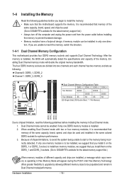
... one direction. When enabling Dual Channel mode with two or four memory modules, it on the DDR3_1 and DDR3_3 sockets. (Go to GIGABYTE's website for optimum performance. 3. DS/SS - - 1-4 Installing the Memory Read the following guidelines before you are unable to insert... the memory, switch the direction. 1-4-1 Dual Channel Memory Configuration This motherboard provides four DDR3 memory sockets and supports Dual Channel Technology. After the memory is installed, the BIOS will double the original memory ...
... one direction. When enabling Dual Channel mode with two or four memory modules, it on the DDR3_1 and DDR3_3 sockets. (Go to GIGABYTE's website for optimum performance. 3. DS/SS - - 1-4 Installing the Memory Read the following guidelines before you are unable to insert... the memory, switch the direction. 1-4-1 Dual Channel Memory Configuration This motherboard provides four DDR3 memory sockets and supports Dual Channel Technology. After the memory is installed, the BIOS will double the original memory ...

Manual
Page 17
Follow the steps below to install DDR3 DIMMs on this motherboard. Place the memory module on the top edge of the memory socket. Spread the retaining clips at both ends of the memory, push down on ...
Follow the steps below to install DDR3 DIMMs on this motherboard. Place the memory module on the top edge of the memory socket. Spread the retaining clips at both ends of the memory, push down on ...

Manual
Page 18
... back panel. 2. Locate an expansion slot that came with your computer. Secure the card's metal bracket to install an expansion card: • Make sure the motherboard supports the expansion card.
... back panel. 2. Locate an expansion slot that came with your computer. Secure the card's metal bracket to install an expansion card: • Make sure the motherboard supports the expansion card.
Manual
Page 19
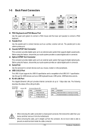
Before using this feature, ensure that your device and then remove it from the motherboard. • When removing the cable, pull it side to side to an external audio system that supports digital optical audio. Parallel Port Use the parallel ...
Before using this feature, ensure that your device and then remove it from the motherboard. • When removing the cable, pull it side to side to an external audio system that supports digital optical audio. Parallel Port Use the parallel ...

Manual
Page 21
... devices and your devices are compliant with the connectors you wish to connect. • Before installing the devices, be sure to the connector on the motherboard. - 21 - Hardware Installation 1-7 Internal Connectors 1 3 17 5 2 10 4 16 13 15 11 8 12 4 1) ATX_12V 2) ATX 3) CPU_FAN 4) SYS_FAN1/2 5) PWR_FAN 6) FDD 7) IDE 8) SATA2_0/1/2/3 9) F_PANEL 6 14 7 9 10) F_AUDIO 11...
... devices and your devices are compliant with the connectors you wish to connect. • Before installing the devices, be sure to the connector on the motherboard. - 21 - Hardware Installation 1-7 Internal Connectors 1 3 17 5 2 10 4 16 13 15 11 8 12 4 1) ATX_12V 2) ATX 3) CPU_FAN 4) SYS_FAN1/2 5) PWR_FAN 6) FDD 7) IDE 8) SATA2_0/1/2/3 9) F_PANEL 6 14 7 9 10) F_AUDIO 11...

Manual
Page 22
...-pin ATX) GND (Only for 2x12-pin ATX) Hardware Installation - 22 - If the 12V power connector is turned off and all the components on the motherboard. Before connecting the power connector, first make sure the power supply is not connected, the computer will not start. The power connector possesses a foolproof design...
...-pin ATX) GND (Only for 2x12-pin ATX) Hardware Installation - 22 - If the 12V power connector is turned off and all the components on the motherboard. Before connecting the power connector, first make sure the power supply is not connected, the computer will not start. The power connector possesses a foolproof design...
Manual
Page 23
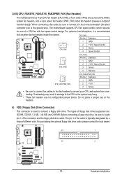
...• Be sure to connect fan cables to the fan headers to connect a floppy disk drive. 3/4/5) CPU_FAN/SYS_FAN1/SYS_FAN2/PWR_FAN (Fan Headers) The motherboard has a 4-pin CPU fan header (CPU_FAN), a 4-pin (SYS_FAN2) and a 3-pin (SYS_FAN1) system fan headers, and a 3-pin power fan ...header (PWR_FAN). Most fan headers possess a foolproof insertion design. The motherboard supports CPU fan speed control, which requires the use of different color. CPU_FAN: Pin No. Definition 1 GND 1 2 +12V / Speed Control CPU_FAN ...
...• Be sure to connect fan cables to the fan headers to connect a floppy disk drive. 3/4/5) CPU_FAN/SYS_FAN1/SYS_FAN2/PWR_FAN (Fan Headers) The motherboard has a 4-pin CPU fan header (CPU_FAN), a 4-pin (SYS_FAN2) and a 3-pin (SYS_FAN1) system fan headers, and a 3-pin power fan ...header (PWR_FAN). Most fan headers possess a foolproof insertion design. The motherboard supports CPU fan speed control, which requires the use of different color. CPU_FAN: Pin No. Definition 1 GND 1 2 +12V / Speed Control CPU_FAN ...

Manual
Page 26
...module that came with your chassis front panel audio module to work or even damage it. Incorrect connection between the module connector and the motherboard header will be present on how to activate AC'97 functionality via the audio software in Chapter 5, "Configuring 2/4/5.1/7.1-Channel Audio." •... simultaneously. If your chassis provides an AC'97 front panel audio module, refer to the instructions on both of the motherboard header. 10) F_AUDIO (Front Panel Audio Header) The front panel audio header supports Intel High Definition audio (HD) and AC'97 ...
...module that came with your chassis front panel audio module to work or even damage it. Incorrect connection between the module connector and the motherboard header will be present on how to activate AC'97 functionality via the audio software in Chapter 5, "Configuring 2/4/5.1/7.1-Channel Audio." •... simultaneously. If your chassis provides an AC'97 front panel audio module, refer to the instructions on both of the motherboard header. 10) F_AUDIO (Front Panel Audio Header) The front panel audio header supports Intel High Definition audio (HD) and AC'97 ...


