
Manual
Page 3
... motherboard looks like this manual may be made by GIGABYTE without GIGABYTE's prior written permission. Example: Changes to their respective owners. No part of the product, read the User's Manual. The trademarks mentioned in this manual are legally registered to the specifications and features in the use GIGABYTE's unique features, read or download the information on/from the Support&Downloads\Motherboard\Technology Guide page on your motherboard revision before updating motherboard BIOS, drivers...
... motherboard looks like this manual may be made by GIGABYTE without GIGABYTE's prior written permission. Example: Changes to their respective owners. No part of the product, read the User's Manual. The trademarks mentioned in this manual are legally registered to the specifications and features in the use GIGABYTE's unique features, read or download the information on/from the Support&Downloads\Motherboard\Technology Guide page on your motherboard revision before updating motherboard BIOS, drivers...

Manual
Page 4
... Box Contents...6 Optional Items...6 GA-EP41T-USB3 Motherboard Layout 7 GA-EP41T-USB3 Motherboard Block Diagram 8 Chapter 1 Hardware Installation 9 1-1 Installation Precautions 9 1-2 Product Specifications 10 1-3 Installing the CPU and CPU Cooler 13 1-3-1 Installing the CPU 13 1-3-2 Installing the CPU Cooler 15 1-4 Installing the Memory 16 1-4-1 Dual Channel Memory Configuration 16 1-4-2 Installing a Memory 17 1-5 Installing an Expansion Card 18 1-6 Back Panel Connectors 19 1-7 Internal Connectors 21 Chapter 2 BIOS Setup 31 2-1 Startup Screen 32 2-2 The Main Menu 33 2-3 MB...
... Box Contents...6 Optional Items...6 GA-EP41T-USB3 Motherboard Layout 7 GA-EP41T-USB3 Motherboard Block Diagram 8 Chapter 1 Hardware Installation 9 1-1 Installation Precautions 9 1-2 Product Specifications 10 1-3 Installing the CPU and CPU Cooler 13 1-3-1 Installing the CPU 13 1-3-2 Installing the CPU Cooler 15 1-4 Installing the Memory 16 1-4-1 Dual Channel Memory Configuration 16 1-4-2 Installing a Memory 17 1-5 Installing an Expansion Card 18 1-6 Back Panel Connectors 19 1-7 Internal Connectors 21 Chapter 2 BIOS Setup 31 2-1 Startup Screen 32 2-2 The Main Menu 33 2-3 MB...
Manual
Page 12
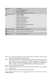
... memory size displayed will be less than 4 GB. (Note 2) Because of chipset limitations, to avoid the system being unable to start or the memory being incorrectly detected, if only one memory module is to GIGABYTE's website for the latest memory support list.) (Note 3) Two share the same ports with USB 3.0. (Note 4) Whether the CPU/system fan speed control function is supported will depend on the CPU/system cooler you install...
... memory size displayed will be less than 4 GB. (Note 2) Because of chipset limitations, to avoid the system being unable to start or the memory being incorrectly detected, if only one memory module is to GIGABYTE's website for the latest memory support list.) (Note 3) Two share the same ports with USB 3.0. (Note 4) Whether the CPU/system fan speed control function is supported will depend on the CPU/system cooler you install...
Manual
Page 16
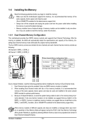
... DDR3_4 Due to insert the memory, switch the direction. 1-4-1 Dual Channel Memory Configuration This motherboard provides four DDR3 memory sockets and supports Dual Channel Technology. DS/SS - - - - Dual Channel mode cannot be installed, we suggest that memory of the same capacity, brand, speed, and chips be used . (Go to GIGABYTE's website for the latest memory support list.) When memory modules of chipset limitations, to avoid the system being unable to start or the memory being incorrectly detected, if only...
... DDR3_4 Due to insert the memory, switch the direction. 1-4-1 Dual Channel Memory Configuration This motherboard provides four DDR3 memory sockets and supports Dual Channel Technology. DS/SS - - - - Dual Channel mode cannot be installed, we suggest that memory of the same capacity, brand, speed, and chips be used . (Go to GIGABYTE's website for the latest memory support list.) When memory modules of chipset limitations, to avoid the system being unable to start or the memory being incorrectly detected, if only...

Manual
Page 18
... card: • Make sure the motherboard supports the expansion card. Carefully read the manual that supports your card. Locate an expansion slot that came with a screw. 5. Turn on the slot and then lift the card straight out from the chassis back panel. 2. Example: Installing and Removing a PCI Express x16 Graphics Card: • Installing a Graphics Card: Gently push down on the card until it is securely seated in your operating system. After installing all expansion cards, replace the chassis...
... card: • Make sure the motherboard supports the expansion card. Carefully read the manual that supports your card. Locate an expansion slot that came with a screw. 5. Turn on the slot and then lift the card straight out from the chassis back panel. 2. Example: Installing and Removing a PCI Express x16 Graphics Card: • Installing a Graphics Card: Gently push down on the card until it is securely seated in your operating system. After installing all expansion cards, replace the chassis...
Manual
Page 23
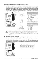
... wire). Before connecting a floppy disk drive, be installed inside the chassis. For purchasing the optional floppy disk drive cable, please contact the local dealer. 33 1 34 2 - 23 - Overheating may hang. • These fan headers are : 360 KB, 720 KB, 1.2 MB, 1.44 MB, and 2.88 MB. 3/4/5) CPU_FAN/SYS_FAN1/SYS_FAN2/PWR_FAN (Fan Headers) The motherboard has a 4-pin CPU fan header (CPU_FAN), a 4-pin (SYS_FAN2) and a 3-pin (SYS_FAN1) system fan headers, and a 3-pin power fan header (PWR_FAN). The motherboard supports CPU fan speed control, which requires the use of the connector...
... wire). Before connecting a floppy disk drive, be installed inside the chassis. For purchasing the optional floppy disk drive cable, please contact the local dealer. 33 1 34 2 - 23 - Overheating may hang. • These fan headers are : 360 KB, 720 KB, 1.2 MB, 1.44 MB, and 2.88 MB. 3/4/5) CPU_FAN/SYS_FAN1/SYS_FAN2/PWR_FAN (Fan Headers) The motherboard has a 4-pin CPU fan header (CPU_FAN), a 4-pin (SYS_FAN2) and a 3-pin (SYS_FAN1) system fan headers, and a 3-pin power fan header (PWR_FAN). The motherboard supports CPU fan speed control, which requires the use of the connector...
Manual
Page 28
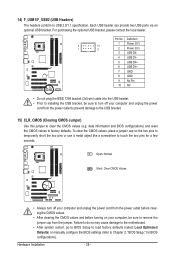
... (Clearing CMOS Jumper) Use this jumper to Chapter 2, "BIOS Setup," for a few seconds. Hardware Installation - 28 - To clear the CMOS values, place a jumper cap on your computer and unplug the power cord from the jumper. Failure to do so may cause damage to the motherboard. • After system restart, go to BIOS Setup to load factory defaults (select Load Optimized Defaults) or manually configure the BIOS settings (refer to clear the CMOS values (e.g. 14) F_USB1/F_USB2 (USB Headers) The headers...
... (Clearing CMOS Jumper) Use this jumper to Chapter 2, "BIOS Setup," for a few seconds. Hardware Installation - 28 - To clear the CMOS values, place a jumper cap on your computer and unplug the power cord from the jumper. Failure to do so may cause damage to the motherboard. • After system restart, go to BIOS Setup to load factory defaults (select Load Optimized Defaults) or manually configure the BIOS settings (refer to clear the CMOS values (e.g. 14) F_USB1/F_USB2 (USB Headers) The headers...

Manual
Page 31
... motherboard supplies the necessary power to the CMOS to clear the CMOS values.) - 31 - To upgrade the BIOS, use either the GIGABYTE Q-Flash or @BIOS utility. • Q-Flash allows the user to quickly and easily upgrade or back up BIOS without entering the operating system. • @BIOS is turned on using the current version of BIOS, it with caution. BIOS Setup To access the BIOS Setup program, press the key during the POST when the power is a Windows-based utility that allows the user...
... motherboard supplies the necessary power to the CMOS to clear the CMOS values.) - 31 - To upgrade the BIOS, use either the GIGABYTE Q-Flash or @BIOS utility. • Q-Flash allows the user to quickly and easily upgrade or back up BIOS without entering the operating system. • @BIOS is turned on using the current version of BIOS, it with caution. BIOS Setup To access the BIOS Setup program, press the key during the POST when the power is a Windows-based utility that allows the user...

Manual
Page 32
Motherboard Model BIOS Version EP41T-USB3 E2 . . . . : BIOS Setup : XpressRecovery2 : Boot Menu : Qflash 11/30/2009-G41-ICH7-6A79PG0BC-00 Function Keys Function Keys Function Keys: : POST SCREEN Press the key to set the first boot device without having to accept. You can be based on page 46. : BIOS SETUP\Q-FLASH Press the key to enter BIOS Setup or to access the Q-Flash utility in BIOS Setup. : XPRESS RECOVERY2 If you to show the BIOS POST screen at system startup, refer to the instructions on the...
Motherboard Model BIOS Version EP41T-USB3 E2 . . . . : BIOS Setup : XpressRecovery2 : Boot Menu : Qflash 11/30/2009-G41-ICH7-6A79PG0BC-00 Function Keys Function Keys Function Keys: : POST SCREEN Press the key to set the first boot device without having to accept. You can be based on page 46. : BIOS SETUP\Q-FLASH Press the key to enter BIOS Setup or to access the Q-Flash utility in BIOS Setup. : XPRESS RECOVERY2 If you to show the BIOS POST screen at system startup, refer to the instructions on the...
Manual
Page 34
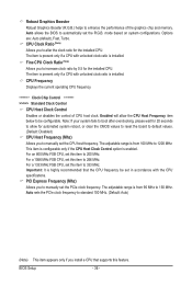
... CPU, memory, etc. Standard CMOS Features Use this menu to configure the system time and date, hard drive types, floppy disk drive types, and the type of errors that stop the system boot, etc. Advanced BIOS Features Use this menu to configure the device boot order, advanced features available on the CPU, and the primary display adapter. Integrated Peripherals Use this menu to configure all peripheral devices, such as IDE, SATA, USB, integrated audio, and integrated LAN, etc. Power Management Setup Use...
... CPU, memory, etc. Standard CMOS Features Use this menu to configure the system time and date, hard drive types, floppy disk drive types, and the type of errors that stop the system boot, etc. Advanced BIOS Features Use this menu to configure the device boot order, advanced features available on the CPU, and the primary display adapter. Integrated Peripherals Use this menu to configure all peripheral devices, such as IDE, SATA, USB, integrated audio, and integrated LAN, etc. Power Management Setup Use...
Manual
Page 35
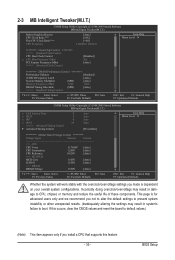
... Clock Control x CPU Host Frequency (Mhz) PCI Express Frequency (Mhz) >>>>> Advanced Clock Control [Disabled] 266 [Auto] ******** DRAM Performance Control ******** Performance Enhance [Standard] (C)MCH Frequency Latch [Auto] System Memory Multiplier (SPD) [Auto] Memory Frequency (Mhz) 1066 1066 DRAM Timing Selectable (SPD) [Auto] >>>>> Standard Timing Control Move Enter: Select F5: Previous Values +/-/PU/PD: Value F10: Save F6: Fail-Safe Defaults ESC: Exit F1: General Help F7: Optimized Defaults CMOS Setup Utility-Copyright (C) 1984-2009 Award Software...
... Clock Control x CPU Host Frequency (Mhz) PCI Express Frequency (Mhz) >>>>> Advanced Clock Control [Disabled] 266 [Auto] ******** DRAM Performance Control ******** Performance Enhance [Standard] (C)MCH Frequency Latch [Auto] System Memory Multiplier (SPD) [Auto] Memory Frequency (Mhz) 1066 1066 DRAM Timing Selectable (SPD) [Auto] >>>>> Standard Timing Control Move Enter: Select F5: Previous Values +/-/PU/PD: Value F10: Save F6: Fail-Safe Defaults ESC: Exit F1: General Help F7: Optimized Defaults CMOS Setup Utility-Copyright (C) 1984-2009 Award Software...
Manual
Page 36
... CMOS values to reset the board to default values. (Default: Disabled) CPU Host Frequency (Mhz) Allows you to increase clock ratio by 0.5 for the installed CPU. Note: If your system fails to boot after overclocking, please wait for 20 seconds to 150 MHz. The adjustable range is highly recommended that supports this item to 266 MHz. For a 1066 MHz FSB CPU, set the R.G.B. mode based on system configurations. Auto sets the PCIe clock frequency...
... CMOS values to reset the board to default values. (Default: Disabled) CPU Host Frequency (Mhz) Allows you to increase clock ratio by 0.5 for the installed CPU. Note: If your system fails to boot after overclocking, please wait for 20 seconds to 150 MHz. The adjustable range is highly recommended that supports this item to 266 MHz. For a 1066 MHz FSB CPU, set the R.G.B. mode based on system configurations. Auto sets the PCIe clock frequency...

Manual
Page 44
... Set Supervisor/User Password item in the BIOS Main Menu. Options are: Floppy, LS120, Hard Disk, CDROM, ZIP, USB-FDD, USB-ZIP, USB-CDROM, USB-HDD, Legacy LAN, Disabled. After configuring this menu when finished. For more information about Intel CPUs' unique features, please visit Intel's website. Use the up or down arrow key to select a device and press to deliver greater efficiency for daily use. (Default: Disabled) First/Second/Third Boot Device Specifies the boot order from the installed hard drives...
... Set Supervisor/User Password item in the BIOS Main Menu. Options are: Floppy, LS120, Hard Disk, CDROM, ZIP, USB-FDD, USB-ZIP, USB-CDROM, USB-HDD, Legacy LAN, Disabled. After configuring this menu when finished. For more information about Intel CPUs' unique features, please visit Intel's website. Use the up or down arrow key to select a device and press to deliver greater efficiency for daily use. (Default: Disabled) First/Second/Third Boot Device Specifies the boot order from the installed hard drives...
Manual
Page 47
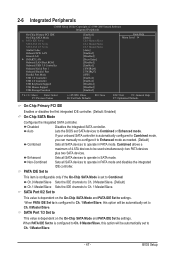
...option will be automatically set to operate in SATA mode. 2-6 Integrated Peripherals CMOS Setup Utility-Copyright (C) 1984-2009 Award Software Integrated Peripherals On-Chip Primary PCI IDE On-Chip SATA Mode x PATA IDE Set to SATA Port 0/2 Set to SATA Port 1/3 Set to operate in PATA mode and disables the integrated IDE controller. Enhanced Sets all SATA devices to Ch. 1 Master/Slave. - 47 - Non-Combined Sets all SATA devices to Azalia Codec Onboard H/W LAN Green LAN } SMART LAN Onboard LAN Boot ROM Onboard USB 3.0 Controller Onboard Serial...
...option will be automatically set to operate in SATA mode. 2-6 Integrated Peripherals CMOS Setup Utility-Copyright (C) 1984-2009 Award Software Integrated Peripherals On-Chip Primary PCI IDE On-Chip SATA Mode x PATA IDE Set to SATA Port 0/2 Set to SATA Port 1/3 Set to operate in PATA mode and disables the integrated IDE controller. Enhanced Sets all SATA devices to Ch. 1 Master/Slave. - 47 - Non-Combined Sets all SATA devices to Azalia Codec Onboard H/W LAN Green LAN } SMART LAN Onboard LAN Boot ROM Onboard USB 3.0 Controller Onboard Serial...
Manual
Page 48
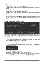
... connected or not. Cable Length Displays the approximate length of wires will dynamically detect if a LAN cable is attached to the following message will be disabled automatically. (Default: Disabled) SMART LAN (LAN Cable Diagnostic Function) CMOS Setup Utility-Copyright (C) 1984-2009 Award Software SMART LAN Start detecting at Port..... When LAN Cable Is Functioning Normally... it will only operate at a normal speed of 10/100/1000 Mbps in Windows mode or when the LAN Boot ROM is detected on the LAN cable connected...
... connected or not. Cable Length Displays the approximate length of wires will dynamically detect if a LAN cable is attached to the following message will be disabled automatically. (Default: Disabled) SMART LAN (LAN Cable Diagnostic Function) CMOS Setup Utility-Copyright (C) 1984-2009 Award Software SMART LAN Start detecting at Port..... When LAN Cable Is Functioning Normally... it will only operate at a normal speed of 10/100/1000 Mbps in Windows mode or when the LAN Boot ROM is detected on the LAN cable connected...

Manual
Page 49
... the boot ROM integrated with the onboard LAN chip. (Default: Disabled) Onboard USB 3.0 Controller (NEC USB 3.0 Controller) Enables or disables the NEC USB 3.0 controller. (Default: Enabled) Onboard Serial Port 1 Enables or disables the first serial port and specifies its base I /O address and corresponding interrupt. BIOS Setup Note: Part 4-5 and Part 7-8 are : SPP (Standard Parallel Port) (default), EPP (Enhanced Parallel Port), ECP (Extended Capabilities Port), ECP+EPP. Options are : Auto, 3F8/IRQ4 (default), 2F8/IRQ3, 3E8/IRQ4, 2E8/IRQ3, Disabled. If a cable problem occurs on Part...
... the boot ROM integrated with the onboard LAN chip. (Default: Disabled) Onboard USB 3.0 Controller (NEC USB 3.0 Controller) Enables or disables the NEC USB 3.0 controller. (Default: Enabled) Onboard Serial Port 1 Enables or disables the first serial port and specifies its base I /O address and corresponding interrupt. BIOS Setup Note: Part 4-5 and Part 7-8 are : SPP (Standard Parallel Port) (default), EPP (Enhanced Parallel Port), ECP (Extended Capabilities Port), ECP+EPP. Options are : Auto, 3F8/IRQ4 (default), 2F8/IRQ3, 3E8/IRQ4, 2E8/IRQ3, Disabled. If a cable problem occurs on Part...
Manual
Page 53
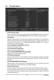
.../power fan is removed, this field will show "Yes", otherwise it will show "No" at next boot. (Default: Disabled) Case Opened Displays the detection status of the chassis intrusion detection device attached to enable this occurs. (Default: Disabled) CPU Smart FAN Control Enables or disables the CPU fan speed control function. Auto lets the BIOS decide whether to the motherboard CI header. CPU Warning Temperature Sets the warning threshold for CPU temperature. Check the fan condition or fan connection when this function. 2-9 PC Health Status CMOS Setup Utility...
.../power fan is removed, this field will show "Yes", otherwise it will show "No" at next boot. (Default: Disabled) Case Opened Displays the detection status of the chassis intrusion detection device attached to enable this occurs. (Default: Disabled) CPU Smart FAN Control Enables or disables the CPU fan speed control function. Auto lets the BIOS decide whether to the motherboard CI header. CPU Warning Temperature Sets the warning threshold for CPU temperature. Check the fan condition or fan connection when this function. 2-9 PC Health Status CMOS Setup Utility...
Manual
Page 64
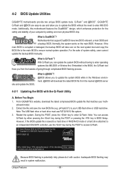
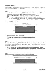
..., Award Software, Inc. What is saved to a hard drive in RAID/AHCI mode or a hard drive attached to an independent IDE/SATA controller, use the key during the POST or pressing the key in the BIOS, the Q-Flash tool frees you can access Q-Flash by adding one more physical BIOS chip. However, if the main BIOS is potentially risky, please do it with the Q-Flash Utility A. Embedded in BIOS Setup. From GIGABYTE's website, download the latest compressed BIOS update file that support DualBIOS have two BIOS onboard, a main BIOS...
..., Award Software, Inc. What is saved to a hard drive in RAID/AHCI mode or a hard drive attached to an independent IDE/SATA controller, use the key during the POST or pressing the key in the BIOS, the Q-Flash tool frees you can access Q-Flash by adding one more physical BIOS chip. However, if the main BIOS is potentially risky, please do it with the Q-Flash Utility A. Embedded in BIOS Setup. From GIGABYTE's website, download the latest compressed BIOS update file that support DualBIOS have two BIOS onboard, a main BIOS...
Manual
Page 65
... a hard drive in RAID/AHCI mode or a hard drive attached to an independent IDE/SATA controller, use the up or down arrow key to Drive Enter : Run hi:Move Total size : 0 ESC:Reset Free size : 0 F10:Power Off 3. Unique Features Select the BIOS update file and press . Update BIOS from Drive Save BIOS to select Update BIOS from the USB flash drive is complete, press any key to return to begin the BIOS update. Q-Flash Utility v2.13 Flash Type/Size MXIC 25L8005 1M Keep0 DfilMe(Is)DfaotuandEnable HDD 0-0 Loa d CMO S Default Enable Update BIOS...
... a hard drive in RAID/AHCI mode or a hard drive attached to an independent IDE/SATA controller, use the up or down arrow key to Drive Enter : Run hi:Move Total size : 0 ESC:Reset Free size : 0 F10:Power Off 3. Unique Features Select the BIOS update file and press . Update BIOS from Drive Save BIOS to select Update BIOS from the USB flash drive is complete, press any key to return to begin the BIOS update. Q-Flash Utility v2.13 Flash Type/Size MXIC 25L8005 1M Keep0 DfilMe(Is)DfaotuandEnable HDD 0-0 Loa d CMO S Default Enable Update BIOS...
Manual
Page 80
... install the onboard HD audio driver from the motherboard driver disk or download the audio driver from the battery holder to stop supplying power to clear the CMOS values. Q: What do the beeps emitted during the POST. A: The following Award BIOS beep code descriptions may help you identify possible computer problems. (For reference only.) 1 short: System boots successfully 1 long, 3 short: Keyboard error 2 short: CMOS setting error 1 long, 9 short: BIOS ROM error 1 long, 1 short: Memory or motherboard error Continuous long beeps: Graphics card not inserted properly 1 long, 2 short...
... install the onboard HD audio driver from the motherboard driver disk or download the audio driver from the battery holder to stop supplying power to clear the CMOS values. Q: What do the beeps emitted during the POST. A: The following Award BIOS beep code descriptions may help you identify possible computer problems. (For reference only.) 1 short: System boots successfully 1 long, 3 short: Keyboard error 2 short: CMOS setting error 1 long, 9 short: BIOS ROM error 1 long, 1 short: Memory or motherboard error Continuous long beeps: Graphics card not inserted properly 1 long, 2 short...


