
Manual
Page 1
GA-E7AUM-DS2H LGA775 socket motherboard for Intel® CoreTM processor family/ Intel® Pentium® processor family/Intel® Celeron® processor family User's Manual Rev. 1001 12ME-E7AUMD2H-1001R
GA-E7AUM-DS2H LGA775 socket motherboard for Intel® CoreTM processor family/ Intel® Pentium® processor family/Intel® Celeron® processor family User's Manual Rev. 1001 12ME-E7AUMD2H-1001R

Manual
Page 2
Motherboard GA-E7AUM-DS2H Sept. 30, 2008 Motherboard GA-E7AUM-DS2H Sept. 30, 2008
Motherboard GA-E7AUM-DS2H Sept. 30, 2008 Motherboard GA-E7AUM-DS2H Sept. 30, 2008

Manual
Page 3
...in any means without prior notice. For example, "REV: 1.0" means the revision of the motherboard is the property of this manual may be made by GIGABYTE without GIGABYTE's prior written permission. All rights reserved. Documentation Classifications In order to assist in the use of...information, check on our website at: http://www.gigabyte.com.tw Identifying Your Motherboard Revision The revision number on our website. Copyright © 2008 GIGA-BYTE TECHNOLOGY CO., LTD. The trademarks mentioned in this product, GIGABYTE provides the following types of documentations: For...
...in any means without prior notice. For example, "REV: 1.0" means the revision of the motherboard is the property of this manual may be made by GIGABYTE without GIGABYTE's prior written permission. All rights reserved. Documentation Classifications In order to assist in the use of...information, check on our website at: http://www.gigabyte.com.tw Identifying Your Motherboard Revision The revision number on our website. Copyright © 2008 GIGA-BYTE TECHNOLOGY CO., LTD. The trademarks mentioned in this product, GIGABYTE provides the following types of documentations: For...
Manual
Page 4
Table of Contents Box Contents ...6 OptionalItems ...6 GA-E7AUM-DS2H Motherboard Layout 7 Block Diagram ...8 Chapter 1 Hardware Installation 9 1-1 Installation Precautions 9 1-2 Product Specifications 10 1-3 Installing the CPU and CPU Cooler 13 1-3-1 Installing the CPU 13 1-3-2 Installing the CPU ...
Table of Contents Box Contents ...6 OptionalItems ...6 GA-E7AUM-DS2H Motherboard Layout 7 Block Diagram ...8 Chapter 1 Hardware Installation 9 1-1 Installation Precautions 9 1-2 Product Specifications 10 1-3 Installing the CPU and CPU Cooler 13 1-3-1 Installing the CPU 13 1-3-2 Installing the CPU ...

Manual
Page 6
...) LPT port cable (Part No. 12CF1-1LP001-01R) COM port cable (Part No. 12CF1-1CM001-32R) - 6 - The box contents are for reference only. Box Contents GA-E7AUM-DS2H motherboard Motherboard driver disk User's Manual Quick Installation Guide One IDE cable and one floppy disk drive cable Two SATA 3Gb/s cables I/O Shield • The box contents...
...) LPT port cable (Part No. 12CF1-1LP001-01R) COM port cable (Part No. 12CF1-1CM001-32R) - 6 - The box contents are for reference only. Box Contents GA-E7AUM-DS2H motherboard Motherboard driver disk User's Manual Quick Installation Guide One IDE cable and one floppy disk drive cable Two SATA 3Gb/s cables I/O Shield • The box contents...

Manual
Page 7
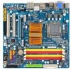
GA-E7AUM-DS2H Motherboard Layout DDR2_1 DDR2_2 PHASE LED DDR2_3 DDR2_4 KB_USB CPU_FAN ATX_12V LGA775 ATX DVI-D VGA HDMI GA-E7AUM-DS2H OPTICAL ESATA 1394 USB LAN USB RTL8211CL AUDIO F_AUDIO PCIEX1 CD_IN PCIEX16 CODEC PCI1 SPDIF_IO PCI2 F_USB3 F_USB2 F_USB1 NVIDIA® GeForce 9400 JMicron 368 IDE M_BIOS IT8718 BAT B_BIOS LPT CLR_CMOS SATA2_3 SATA2_1 TSB43AB23 SATA2_0 SATA2_2 SATA2_4 F_1394 PWR_LED CI FDD SYS_FAN F_PANEL COMA - 7 -
GA-E7AUM-DS2H Motherboard Layout DDR2_1 DDR2_2 PHASE LED DDR2_3 DDR2_4 KB_USB CPU_FAN ATX_12V LGA775 ATX DVI-D VGA HDMI GA-E7AUM-DS2H OPTICAL ESATA 1394 USB LAN USB RTL8211CL AUDIO F_AUDIO PCIEX1 CD_IN PCIEX16 CODEC PCI1 SPDIF_IO PCI2 F_USB3 F_USB2 F_USB1 NVIDIA® GeForce 9400 JMicron 368 IDE M_BIOS IT8718 BAT B_BIOS LPT CLR_CMOS SATA2_3 SATA2_1 TSB43AB23 SATA2_0 SATA2_2 SATA2_4 F_1394 PWR_LED CI FDD SYS_FAN F_PANEL COMA - 7 -

Manual
Page 9
...installation steps or have a problem related to the use of electrostatic discharge (ESD). Chapter 1 Hardware Installation 1-1 Installation Precautions The motherboard contains numerous delicate electronic circuits and components which can lead to damage to system components as well as physical harm to the ...are required for warranty validation. • Always remove the AC power by your hardware components are connected. • To prevent damage to the motherboard, do not have it on top of an antistatic pad or within the computer casing. • Do not place the computer system on an ...
...installation steps or have a problem related to the use of electrostatic discharge (ESD). Chapter 1 Hardware Installation 1-1 Installation Precautions The motherboard contains numerous delicate electronic circuits and components which can lead to damage to system components as well as physical harm to the ...are required for warranty validation. • Always remove the AC power by your hardware components are connected. • To prevent damage to the motherboard, do not have it on top of an antistatic pad or within the computer casing. • Do not place the computer system on an ...
Manual
Page 10
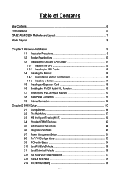
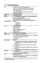
... supporting up to 16 GB of system memory (Note 1) Dual channel memory architecture Support for DDR2 800/667 MHz memory modules (Go to GIGABYTE's website for the latest memory support list.) Chipset: - 1 x D-Sub port - 1 x DVI-D port (Note 2) - 1 x HDMI port ...devices (Note 6) - 1 x eSATA 3Gb/s port on the back panel, 6 via the USB brackets connected to the internal USB headers) GA-E7AUM-DS2H Motherboard - 10 - 1-2 Product Specifications CPU Front Side Bus Chipset Memory Onboard Graphics Audio LAN Expansion Slots Storage Interface IEEE 1394a USB ...
... supporting up to 16 GB of system memory (Note 1) Dual channel memory architecture Support for DDR2 800/667 MHz memory modules (Go to GIGABYTE's website for the latest memory support list.) Chipset: - 1 x D-Sub port - 1 x DVI-D port (Note 2) - 1 x HDMI port ...devices (Note 6) - 1 x eSATA 3Gb/s port on the back panel, 6 via the USB brackets connected to the internal USB headers) GA-E7AUM-DS2H Motherboard - 10 - 1-2 Product Specifications CPU Front Side Bus Chipset Memory Onboard Graphics Audio LAN Expansion Slots Storage Interface IEEE 1394a USB ...
Manual
Page 12
... CPU/system fan speed control function is supported will depend on the CPU/ system cooler you install. (Note 8) Available functions in EasyTune may differ by motherboard model. GA-E7AUM-DS2H Motherboard - 12 -
... CPU/system fan speed control function is supported will depend on the CPU/ system cooler you install. (Note 8) Available functions in EasyTune may differ by motherboard model. GA-E7AUM-DS2H Motherboard - 12 -

Manual
Page 13
... Installation If you may occur. • Set the CPU host frequency in accordance with the CPU specifications. Locate the alignment keys on the motherboard CPU socket and the notches on the computer if the CPU cooler is not recom- LGA775 CPU Socket Alignment Key LGA 775 CPU Alignment Key... Pin One Corner of the CPU. mended that the motherboard supports the CPU. (Go to GIGABYTE's website for the peripherals. The CPU cannot be set the frequency beyond hardware specifications since it does not meet the ...
... Installation If you may occur. • Set the CPU host frequency in accordance with the CPU specifications. Locate the alignment keys on the motherboard CPU socket and the notches on the computer if the CPU cooler is not recom- LGA775 CPU Socket Alignment Key LGA 775 CPU Alignment Key... Pin One Corner of the CPU. mended that the motherboard supports the CPU. (Go to GIGABYTE's website for the peripherals. The CPU cannot be set the frequency beyond hardware specifications since it does not meet the ...

Manual
Page 14
... is properly inserted, replace the load plate and push the CPU socket lever back into its locked position. Follow the steps below to the CPU. GA-E7AUM-DS2H Motherboard - 14 - Step 5: Once the CPU is not installed.) Step 4: Hold the CPU with the socket alignment keys) and gently insert the CPU into the...
... is properly inserted, replace the load plate and push the CPU socket lever back into its locked position. Follow the steps below to the CPU. GA-E7AUM-DS2H Motherboard - 14 - Step 5: Once the CPU is not installed.) Step 4: Hold the CPU with the socket alignment keys) and gently insert the CPU into the...

Manual
Page 15
...on the contrary, is inserted as the example cooler.) Step 1: Apply an even and thin layer of thermal grease on the surface of the motherboard. Inadequately removing the CPU cooler may adhere to the CPU. 1-3-2 Installing the CPU Cooler Follow the steps below to correctly install the CPU cooler ...on the motherboard. (The following procedure uses Intel® boxed cooler as the picture above, the installation is complete. Check that the Male and Female push ...
...on the contrary, is inserted as the example cooler.) Step 1: Apply an even and thin layer of thermal grease on the surface of the motherboard. Inadequately removing the CPU cooler may adhere to the CPU. 1-3-2 Installing the CPU Cooler Follow the steps below to correctly install the CPU cooler ...on the motherboard. (The following procedure uses Intel® boxed cooler as the picture above, the installation is complete. Check that the Male and Female push ...
Manual
Page 16
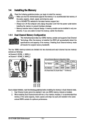
The four DDR2 memory sockets are unable to GIGABYTE's website for optimum performance. GA-E7AUM-DS2H Motherboard - 16 - A memory module can be installed in Dual Channel mode. 1. Enabling Dual Channel memory mode will automatically detect the ... the same capacity, brand, speed, and chips be used . (Go to insert the memory, switch the direction. 1-4-1 Dual Channel Memory Configuration This motherboard provides four DDR2 memory sockets and supports Dual Channel Technology. 1-4 Installing the Memory Read the following : Channel 0: DDR2_1, DDR2_2 Channel 1: DDR2_3, DDR2_4...
The four DDR2 memory sockets are unable to GIGABYTE's website for optimum performance. GA-E7AUM-DS2H Motherboard - 16 - A memory module can be installed in Dual Channel mode. 1. Enabling Dual Channel memory mode will automatically detect the ... the same capacity, brand, speed, and chips be used . (Go to insert the memory, switch the direction. 1-4-1 Dual Channel Memory Configuration This motherboard provides four DDR2 memory sockets and supports Dual Channel Technology. 1-4 Installing the Memory Read the following : Channel 0: DDR2_1, DDR2_2 Channel 1: DDR2_3, DDR2_4...

Manual
Page 17
... , make sure to turn off the computer and unplug the power cord from the power outlet to prevent damage to install DDR2 DIMMs on this motherboard. Step 1: Note the orientation of the memory, push down on the top edge of the memory module. Follow the steps below to correctly install your...
... , make sure to turn off the computer and unplug the power cord from the power outlet to prevent damage to install DDR2 DIMMs on this motherboard. Step 1: Note the orientation of the memory, push down on the top edge of the memory module. Follow the steps below to correctly install your...
Manual
Page 18
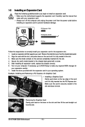
...slot. Remove the metal slot cover from the power outlet before you begin to install an expansion card: • Make sure the motherboard supports the expansion card. If necessary, go to BIOS Setup to make any required BIOS changes for your operating system. Make sure...off the computer and unplug the power cord from the chassis back panel. 2. After installing all expansion cards, replace the chassis cover(s). 6. GA-E7AUM-DS2H Motherboard - 18 - PCI Express x1 Slot PCI Express x16 Slot PCI Slot Follow the steps below to correctly install your expansion card in your ...
...slot. Remove the metal slot cover from the power outlet before you begin to install an expansion card: • Make sure the motherboard supports the expansion card. If necessary, go to BIOS Setup to make any required BIOS changes for your operating system. Make sure...off the computer and unplug the power cord from the chassis back panel. 2. After installing all expansion cards, replace the chassis cover(s). 6. GA-E7AUM-DS2H Motherboard - 18 - PCI Express x1 Slot PCI Express x16 Slot PCI Slot Follow the steps below to correctly install your expansion card in your ...

Manual
Page 19
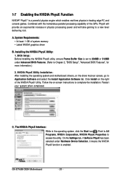
.... (Boost Performance means the Hybrid SLI is enabled.) 2. Hardware Installation The Hybrid SLI Interface: 1. A. Driver Installation: Insert the motherboard driver disk and select Installing Chipset Drivers. Choose Additional displays if you want to show this dialog box. Enabling Hybrid SLI: 1. ... "Advanced BIOS Features", for installation. Hybrid SLI Mode Confirmation: The Hybrid SLI icon appears in the notification area after the motherboard driver installation. BIOS Setup: Enter BIOS Setup to set the following items under the Advanced BIOS Features menu: • Set...
.... (Boost Performance means the Hybrid SLI is enabled.) 2. Hardware Installation The Hybrid SLI Interface: 1. A. Driver Installation: Insert the motherboard driver disk and select Installing Chipset Drivers. Choose Additional displays if you want to show this dialog box. Enabling Hybrid SLI: 1. ... "Advanced BIOS Features", for installation. Hybrid SLI Mode Confirmation: The Hybrid SLI icon appears in the notification area after the motherboard driver installation. BIOS Setup: Enter BIOS Setup to set the following items under the Advanced BIOS Features menu: • Set...
Manual
Page 20
..., on -screen instructions to Application Software and select the Install Application Software tab. GA-E7AUM-DS2H Motherboard - 20 - 1-7 Enabling the NVIDIA PhysX Function NVIDIA® PhysXTM is enabled. Installing the NVIDIA PhysX Utility: 1. Follow the on the driver Autorun screen, go to ...
..., on -screen instructions to Application Software and select the Install Application Software tab. GA-E7AUM-DS2H Motherboard - 20 - 1-7 Enabling the NVIDIA PhysX Function NVIDIA® PhysXTM is enabled. Installing the NVIDIA PhysX Utility: 1. Follow the on the driver Autorun screen, go to ...

Manual
Page 21
... port. Connect a monitor that supports D-Sub connection to prevent an electrical short inside the cable connector. - 21 - Do not rock it straight out from the motherboard. • When removing the cable, pull it side to side to this port. HDMI Port The HDMI (High-Definition Multimedia Interface) provides an all-digital...
... port. Connect a monitor that supports D-Sub connection to prevent an electrical short inside the cable connector. - 21 - Do not rock it straight out from the motherboard. • When removing the cable, pull it side to side to this port. HDMI Port The HDMI (High-Definition Multimedia Interface) provides an all-digital...
Manual
Page 22
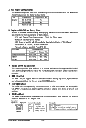
... audio in connector. eSATA 3Gb/s Port The eSATA 3Gb/s port supported by the chipset conforms to SATA 3Gb/s standard and is occurring GA-E7AUM-DS2H Motherboard - 22 - E1200 (1.6 GHz or faster) • Memory: 1 GB of DDR2 800 memory • BIOS Setup: At least...Combination Supported or Not Display DVI-D + D-Sub Yes DVI-D + HDMI No HDMI + D-Sub Yes B. A. Dual Display Configurations: This motherboard provides three ports for more information) • Playback software: CyberLink PowerDVD 8.0 File Format Suitable Resolution Windows XP Windows Vista Non-protected contents ...
... audio in connector. eSATA 3Gb/s Port The eSATA 3Gb/s port supported by the chipset conforms to SATA 3Gb/s standard and is occurring GA-E7AUM-DS2H Motherboard - 22 - E1200 (1.6 GHz or faster) • Memory: 1 GB of DDR2 800 memory • BIOS Setup: At least...Combination Supported or Not Display DVI-D + D-Sub Yes DVI-D + HDMI No HDMI + D-Sub Yes B. A. Dual Display Configurations: This motherboard provides three ports for more information) • Playback software: CyberLink PowerDVD 8.0 File Format Suitable Resolution Windows XP Windows Vista Non-protected contents ...

Manual
Page 24
... 14) F_USB1/F_USB2/F_USB3 15) F_1394 16) COM 17) LPT 18) CLR_CMOS 19) CI 20) PHASE LED Read the following guidelines before turning on the motherboard. Unplug the power cord from the power outlet to prevent damage to the devices. • After installing the device and before connecting external devices: •..., be sure to the connector on the computer, make sure the device cable has been securely attached to turn off the devices and your computer. GA-E7AUM-DS2H Motherboard - 24 -
... 14) F_USB1/F_USB2/F_USB3 15) F_1394 16) COM 17) LPT 18) CLR_CMOS 19) CI 20) PHASE LED Read the following guidelines before turning on the motherboard. Unplug the power cord from the power outlet to prevent damage to the devices. • After installing the device and before connecting external devices: •..., be sure to the connector on the computer, make sure the device cable has been securely attached to turn off the devices and your computer. GA-E7AUM-DS2H Motherboard - 24 -


