Manual
Page 1
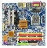
GA-965GM-DS2 (rev. 2.0) Intel® CoreTM 2 Extreme quad-core / CoreTM 2 Quad / Intel® CoreTM 2 Extreme dual-core / CoreTM 2 Duo / Intel® Pentium® Processor Extreme Edition / Intel® Pentium® D / Pentium® 4 LGA775 Processor Motherboard User's Manual Rev. 2002 12ME-965GMDR-2002R * The WEEE marking on the product indicates this product must not be...
GA-965GM-DS2 (rev. 2.0) Intel® CoreTM 2 Extreme quad-core / CoreTM 2 Quad / Intel® CoreTM 2 Extreme dual-core / CoreTM 2 Duo / Intel® Pentium® Processor Extreme Edition / Intel® Pentium® D / Pentium® 4 LGA775 Processor Motherboard User's Manual Rev. 2002 12ME-965GMDR-2002R * The WEEE marking on the product indicates this product must not be...
Manual
Page 2
Motherboard GA-965GM-DS2 (rev. 2.0) Oct. 1, 2006 Motherboard GA-965GM-DS2 (rev. 2.0) Oct. 1, 2006
Motherboard GA-965GM-DS2 (rev. 2.0) Oct. 1, 2006 Motherboard GA-965GM-DS2 (rev. 2.0) Oct. 1, 2006
Manual
Page 4
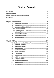
Table of Contents ItemChecklist ...6 OptionalAccessories ...6 GA-965GM-DS2 (rev. 2.0) Motherboard Layout 7 Block Diagram ...8 Chapter 1 Hardware Installation 9 1-1 Considerations Prior to Installation 9 1-2 Feature Summary 10 1-3 Installation of the CPU and CPU Cooler 12 1-3-1 Installation of the CPU ...
Table of Contents ItemChecklist ...6 OptionalAccessories ...6 GA-965GM-DS2 (rev. 2.0) Motherboard Layout 7 Block Diagram ...8 Chapter 1 Hardware Installation 9 1-1 Considerations Prior to Installation 9 1-2 Feature Summary 10 1-3 Installation of the CPU and CPU Cooler 12 1-3-1 Installation of the CPU ...
Manual
Page 7
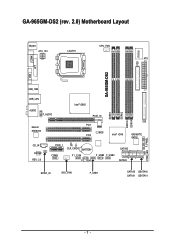
GA-965GM-DS2 (rev. 2.0) Motherboard Layout KB_MS ATX_12V LGA775 CPU_FAN ATX GA-965GM-DS2 FDD IT8718 COMA LPT VGA USB_1394 USB_LAN Intel® G965 AUDIO F_AUDIO Marvell 88E8056 PCIE_16 PCI1 BIOS PCI2 Intel® ICH8 IDE GIGABYTE SATA2 CD_IN CODEC REV: 2.0 PCIE_1 CI CLR_CMOS BATTERY COMB F1_1394 F2_1394 F_USB2 F_USB3 SATAII2 SATAII3 SPDIF_IO SYS _FAN F_USB1 SATAII0 GSATAII0 SATAII1 GSATAII1 DDRII1 DDRII2 DDRII3 DDRII4 PWR_LED F_PANEL - 7 -
GA-965GM-DS2 (rev. 2.0) Motherboard Layout KB_MS ATX_12V LGA775 CPU_FAN ATX GA-965GM-DS2 FDD IT8718 COMA LPT VGA USB_1394 USB_LAN Intel® G965 AUDIO F_AUDIO Marvell 88E8056 PCIE_16 PCI1 BIOS PCI2 Intel® ICH8 IDE GIGABYTE SATA2 CD_IN CODEC REV: 2.0 PCIE_1 CI CLR_CMOS BATTERY COMB F1_1394 F2_1394 F_USB2 F_USB3 SATAII2 SATAII3 SPDIF_IO SYS _FAN F_USB1 SATAII0 GSATAII0 SATAII1 GSATAII1 DDRII1 DDRII2 DDRII3 DDRII4 PWR_LED F_PANEL - 7 -
Manual
Page 8
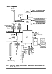
... PCIe CLK (100 MHz) LGA775 Processor CPU CLK+/-(266/200/133 MHz) VGA PCI Express x16 2 SATA 3Gb/s LAN ATA33/66/100/133 IDE Channel GIGABYTE RJ45 Marvell SATA2 88E8056 PCI Express Bus x 1 x1 x1 PCIe CLK (100 MHz) 1 PCI Express x1 PCI Bus TSB43AB23 Host Interface DDRII 800/667/533... Line-In SPDIF In SPDIF Out 2 PCI PCI CLK(33 MHz) 10 USB Ports (Note) To use a DDR II 800/667 memory module on the motherboard, you must install an 1066/ 800 MHz FSB processor. - 8 -
... PCIe CLK (100 MHz) LGA775 Processor CPU CLK+/-(266/200/133 MHz) VGA PCI Express x16 2 SATA 3Gb/s LAN ATA33/66/100/133 IDE Channel GIGABYTE RJ45 Marvell SATA2 88E8056 PCI Express Bus x 1 x1 x1 PCIe CLK (100 MHz) 1 PCI Express x1 PCI Bus TSB43AB23 Host Interface DDRII 800/667/533... Line-In SPDIF In SPDIF Out 2 PCI PCI CLK(33 MHz) 10 USB Ports (Note) To use a DDR II 800/667 memory module on the motherboard, you must install an 1066/ 800 MHz FSB processor. - 8 -
Manual
Page 9
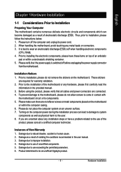
... the instructions below: 1. Thus, prior to use of the product, please consult a certified computer technician. Prior to be an unofficial Gigabyte product. - 9 - Please make sure there are connected. 4. Before using the product, please verify that the power supply is best... in the provided manual. 3. Hardware Installation English Chapter 1 Hardware Installation 1-1 Considerations Prior to Installation Preparing Your Computer The motherboard contains numerous delicate electronic circuits and components which can lead to damage to system components as well as a result of violating...
... the instructions below: 1. Thus, prior to use of the product, please consult a certified computer technician. Prior to be an unofficial Gigabyte product. - 9 - Please make sure there are connected. 4. Before using the product, please verify that the power supply is best... in the provided manual. 3. Hardware Installation English Chapter 1 Hardware Installation 1-1 Considerations Prior to Installation Preparing Your Computer The motherboard contains numerous delicate electronic circuits and components which can lead to damage to system components as well as a result of violating...
Manual
Page 10
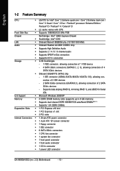
nection of 2 IDE devices - 2 SATA 3Gb/s connectors (GSATAII0,1), allowing connection of 4 SATA 3Gb/s devices Š Onboard GIGABYTE SATA2 chip - 1 IDE connector (UDMA 33/ATA 66/ATA 100/ATA 133), allowing con- Supports data striping (RAID 0), mirroring (RAID 1), and JBOD for Intel® .../s connectors Š 1 CPU fan connector Š 1 system fan connector Š 1 front panel connector Š 1 front audio connector Š 1 CD In connector Š 1 power LED connector GA-965GM-DS2 (rev. 2.0) Motherboard - 10 -
nection of 2 IDE devices - 2 SATA 3Gb/s connectors (GSATAII0,1), allowing connection of 4 SATA 3Gb/s devices Š Onboard GIGABYTE SATA2 chip - 1 IDE connector (UDMA 33/ATA 66/ATA 100/ATA 133), allowing con- Supports data striping (RAID 0), mirroring (RAID 1), and JBOD for Intel® .../s connectors Š 1 CPU fan connector Š 1 system fan connector Š 1 front panel connector Š 1 front audio connector Š 1 CD In connector Š 1 power LED connector GA-965GM-DS2 (rev. 2.0) Motherboard - 10 -

Manual
Page 11
... Security (OEM version) Form Factor Š Micro ATX form factor; 24.4cm x 24.4cm (Note 1) To use a DDR II 800/667 memory module on the motherboard, you must install an 1066/ 800 MHz FSB processor. (Note 2) EasyTune functions may vary depending on different...
... Security (OEM version) Form Factor Š Micro ATX form factor; 24.4cm x 24.4cm (Note 1) To use a DDR II 800/667 memory module on the motherboard, you must install an 1066/ 800 MHz FSB processor. (Note 2) EasyTune functions may vary depending on different...
Manual
Page 12
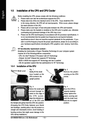
...the CPU, please comply with the triangle and gently insert the CPU into its original position. Chipset: An Intel® Chipset that the motherboard supports the CPU. 2. OS: An operation system that might cause damage to system use, otherwise overheating and permanent damage of the CPU..., please do so according to the upright position. Fig. 2 Remove the plastic covering on the CPU prior to the CPU during installation.) GA-965GM-DS2 (rev. 2.0) Motherboard - 12 - Fig. 4 Once the CPU is installed on the CPU socket. If you install the CPU in accordance with HT Technology...
...the CPU, please comply with the triangle and gently insert the CPU into its original position. Chipset: An Intel® Chipset that the motherboard supports the CPU. 2. OS: An operation system that might cause damage to system use, otherwise overheating and permanent damage of the CPU..., please do so according to the upright position. Fig. 2 Remove the plastic covering on the CPU prior to the CPU during installation.) GA-965GM-DS2 (rev. 2.0) Motherboard - 12 - Fig. 4 Once the CPU is installed on the CPU socket. If you install the CPU in accordance with HT Technology...
Manual
Page 13
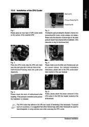
... The top of Female Push Pin Female Push Pin Fig.1 Please apply an even layer of CPU cooler paste on the motherboard. To prevent such an occurrence, it is only for Intel boxed fan) Fig. 3 Place the CPU cooler atop the...) Fig. 5 Please check the back of the installed CPU. The CPU cooler may adhere to the pin hole on the motherboard.Pressing down the push pins diagonally. Fig. 2 (Turning the push pin along the direction of arrow is to remove the ... detailed installation instructions, please refer to the CPU fan header located on the surface of motherboard after installing.
... The top of Female Push Pin Female Push Pin Fig.1 Please apply an even layer of CPU cooler paste on the motherboard. To prevent such an occurrence, it is only for Intel boxed fan) Fig. 3 Place the CPU cooler atop the...) Fig. 5 Please check the back of the installed CPU. The CPU cooler may adhere to the pin hole on the motherboard.Pressing down the push pins diagonally. Fig. 2 (Turning the push pin along the direction of arrow is to remove the ... detailed installation instructions, please refer to the CPU fan header located on the surface of motherboard after installing.
Manual
Page 14
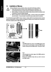
...The DIMM socket has a notch, so the DIMM memory module can differ with the following conditions: 1. Then push it down. The motherboard supports DDRII memory modules, whereby BIOS will automatically detect memory capacity and specifications. The memory capacity used can only fit in only one ... and brand be installed in one direction. If you wish to insert the module, please switch the direction. GA-965GM-DS2 (rev. 2.0) Motherboard - 14 - Memory modules have a foolproof insertion design. Reverse the installation steps when you are designed so that the memory used . ...
...The DIMM socket has a notch, so the DIMM memory module can differ with the following conditions: 1. Then push it down. The motherboard supports DDRII memory modules, whereby BIOS will automatically detect memory capacity and specifications. The memory capacity used can only fit in only one ... and brand be installed in one direction. If you wish to insert the module, please switch the direction. GA-965GM-DS2 (rev. 2.0) Motherboard - 14 - Memory modules have a foolproof insertion design. Reverse the installation steps when you are designed so that the memory used . ...
Manual
Page 16
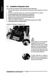
... to the onboard PCI Express x16 slot and press firmly down on the slot. Remove your computer's chassis cover. 7. Install related driver from BIOS. 8. GA-965GM-DS2 (rev. 2.0) Motherboard - 16 - Replace the screw to secure the slot bracket of the PCI Express x16 slot when you try to install/ uninstall the VGA card. Press...
... to the onboard PCI Express x16 slot and press firmly down on the slot. Remove your computer's chassis cover. 7. Install related driver from BIOS. 8. GA-965GM-DS2 (rev. 2.0) Motherboard - 16 - Replace the screw to secure the slot bracket of the PCI Express x16 slot when you try to install/ uninstall the VGA card. Press...
Manual
Page 18
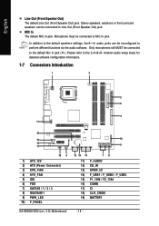
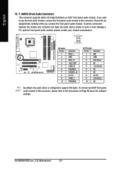
... 19 14 78 11) F_AUDIO 12) CD_IN 13) SPDIF_IO 14) F_USB1 / F_USB2 / F_USB3 15) F1_1394 / F2_1394 16) COMB 17) CI 18) CLR_CMOS 19) BATTERY GA-965GM-DS2 (rev. 2.0) Motherboard - 18 - English Line Out (Front Speaker Out) The default Line Out (Front Speaker Out) jack. In addition to the default speakers settings, the ~ audio jacks...
... 19 14 78 11) F_AUDIO 12) CD_IN 13) SPDIF_IO 14) F_USB1 / F_USB2 / F_USB3 15) F1_1394 / F2_1394 16) COMB 17) CI 18) CLR_CMOS 19) BATTERY GA-965GM-DS2 (rev. 2.0) Motherboard - 18 - English Line Out (Front Speaker Out) The default Line Out (Front Speaker Out) jack. In addition to the default speakers settings, the ~ audio jacks...
Manual
Page 19
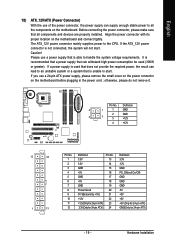
... ATX_12V power connector is not connected, the system will not start . If a power supply is recommended that a power supply that all the components on the motherboard. Definition 2 1 1 GND 2 GND 4 3 3 +12V 4 +12V 12 24 1 13 Pin No. 1 2 3 4 5 6 7 8 9 10 11 12 Definition 3.3V 3.3V GND +5V...not remove it. If you use a 24-pin ATX power supply, please remove the small cover on the power connector on the motherboard and connect tightly. Hardware Installation Please use a power supply that is able to all components and devices are properly installed. Before ...
... ATX_12V power connector is not connected, the system will not start . If a power supply is recommended that a power supply that all the components on the motherboard. Definition 2 1 1 GND 2 GND 4 3 3 +12V 4 +12V 12 24 1 13 Pin No. 1 2 3 4 5 6 7 8 9 10 11 12 Definition 3.3V 3.3V GND +5V...not remove it. If you use a 24-pin ATX power supply, please remove the small cover on the power connector on the motherboard and connect tightly. Hardware Installation Please use a power supply that is able to all components and devices are properly installed. Before ...
Manual
Page 20
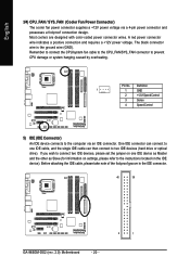
... the instructions located on the IDE device). Before attaching the IDE cable, please take note of the foolproof groove in the IDE connector. 40 39 GA-965GM-DS2 (rev. 2.0) Motherboard - 20 - 2 1 English 3/4) CPU_FAN / SYS_FAN (Cooler Fan Power Connector) The cooler fan power connector supplies a +12V power voltage via an IDE connector. Most coolers are...
... the instructions located on the IDE device). Before attaching the IDE cable, please take note of the foolproof groove in the IDE connector. 40 39 GA-965GM-DS2 (rev. 2.0) Motherboard - 20 - 2 1 English 3/4) CPU_FAN / SYS_FAN (Cooler Fan Power Connector) The cooler fan power connector supplies a +12V power voltage via an IDE connector. Most coolers are...
Manual
Page 22
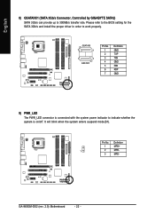
... is connected with the system power indicator to 300MB/s transfer rate. It will blink when the system enters suspend mode(S1). GA-965GM-DS2 (rev. 2.0) Motherboard - 22 - English 8) GSATAII0/1 (SATA 3Gb/s Connector, Controlled by GIGABYTE SATA2) SATA 3Gb/s can provide up to indicate whether the system is on/off. Pin No. Please refer to the...
... is connected with the system power indicator to 300MB/s transfer rate. It will blink when the system enters suspend mode(S1). GA-965GM-DS2 (rev. 2.0) Motherboard - 22 - English 8) GSATAII0/1 (SATA 3Gb/s Connector, Controlled by GIGABYTE SATA2) SATA 3Gb/s can provide up to indicate whether the system is on/off. Pin No. Please refer to the...
Manual
Page 24
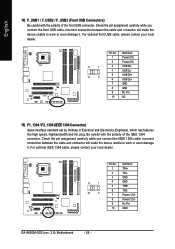
... chassis manufacturer. 10 9 2 1 HD Audio: Pin No. 1 2 3 4 5 6 7 8 9 10 Definition MIC2_L GND MIC2_R -ACZ_DET LINE2_R FSENSE1 FAUDIO_JD No Pin LINE2_L FSENSE2 AC'97 Audio: Pin No. GA-965GM-DS2 (rev. 2.0) Motherboard - 24 - If you connect the front panel audio module.
... chassis manufacturer. 10 9 2 1 HD Audio: Pin No. 1 2 3 4 5 6 7 8 9 10 Definition MIC2_L GND MIC2_R -ACZ_DET LINE2_R FSENSE1 FAUDIO_JD No Pin LINE2_L FSENSE2 AC'97 Audio: Pin No. GA-965GM-DS2 (rev. 2.0) Motherboard - 24 - If you connect the front panel audio module.
Manual
Page 26
... optional front USB cable, please contact your local dealer. 9 1 10 2 Pin No. 1 2 3 4 5 6 7 8 9 10 Definition TPA+ TPAGND GND TPB+ TPBPower (12V) Power (12V) No Pin GND GA-965GM-DS2 (rev. 2.0) Motherboard - 26 - English 14) F_USB1 / F_USB2 / F_USB3 (Front USB Connectors) Be careful with the polarity of the front USB connector.
... optional front USB cable, please contact your local dealer. 9 1 10 2 Pin No. 1 2 3 4 5 6 7 8 9 10 Definition TPA+ TPAGND GND TPB+ TPBPower (12V) Power (12V) No Pin GND GA-965GM-DS2 (rev. 2.0) Motherboard - 26 - English 14) F_USB1 / F_USB2 / F_USB3 (Front USB Connectors) Be careful with the polarity of the front USB connector.
Manual
Page 28
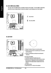
... the same or equivalent type recommended by this header. Dispose of used batteries according to erase CMOS... 1. Open: Normal Short: Clear CMOS 19) BATTERY GA-965GM-DS2 (rev. 2.0) Motherboard Danger of this header. To clear CMOS, temporarily short the two pins. If you can use of explosion if battery is incorrectly replaced. Plug the...
... the same or equivalent type recommended by this header. Dispose of used batteries according to erase CMOS... 1. Open: Normal Short: Clear CMOS 19) BATTERY GA-965GM-DS2 (rev. 2.0) Motherboard Danger of this header. To clear CMOS, temporarily short the two pins. If you can use of explosion if battery is incorrectly replaced. Plug the...
Manual
Page 29
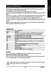
... caution and avoid inadequate operation that may result in the CMOS SRAM of the screen. Because BIOS flashing is displayed at the bottom of the motherboard. English Chapter 2 BIOS Setup BIOS (Basic Input and Output System) includes a CMOS SETUP utility which allows user to configure required settings or to...the BIOS POST (Power-On Self Test) will take you wish to upgrade to the CMOS SRAM. When the power is turned on the motherboard supplies the necessary power to a new BIOS, either Gigabyte's Q-Flash or @BIOS utility can enter the BIOS setup screen by pressing "Ctrl + F1".
... caution and avoid inadequate operation that may result in the CMOS SRAM of the screen. Because BIOS flashing is displayed at the bottom of the motherboard. English Chapter 2 BIOS Setup BIOS (Basic Input and Output System) includes a CMOS SETUP utility which allows user to configure required settings or to...the BIOS POST (Power-On Self Test) will take you wish to upgrade to the CMOS SRAM. When the power is turned on the motherboard supplies the necessary power to a new BIOS, either Gigabyte's Q-Flash or @BIOS utility can enter the BIOS setup screen by pressing "Ctrl + F1".


