Manual
Page 1
GA-965GM-DS2 (rev. 2.0) Intel® CoreTM 2 Extreme quad-core / CoreTM 2 Quad / Intel® CoreTM 2 Extreme dual-core / CoreTM 2 Duo / Intel® Pentium® Processor Extreme Edition / Intel&#...
GA-965GM-DS2 (rev. 2.0) Intel® CoreTM 2 Extreme quad-core / CoreTM 2 Quad / Intel® CoreTM 2 Extreme dual-core / CoreTM 2 Duo / Intel® Pentium® Processor Extreme Edition / Intel&#...
Manual
Page 2
Motherboard GA-965GM-DS2 (rev. 2.0) Oct. 1, 2006 Motherboard GA-965GM-DS2 (rev. 2.0) Oct. 1, 2006
Motherboard GA-965GM-DS2 (rev. 2.0) Oct. 1, 2006 Motherboard GA-965GM-DS2 (rev. 2.0) Oct. 1, 2006
Manual
Page 4
Table of Contents ItemChecklist ...6 OptionalAccessories ...6 GA-965GM-DS2 (rev. 2.0) Motherboard Layout 7 Block Diagram ...8 Chapter 1 Hardware Installation 9 1-1 Considerations Prior to Installation 9 1-2 Feature Summary 10 1-3 Installation of the CPU and CPU Cooler 12 1-3-1 Installation of ...
Table of Contents ItemChecklist ...6 OptionalAccessories ...6 GA-965GM-DS2 (rev. 2.0) Motherboard Layout 7 Block Diagram ...8 Chapter 1 Hardware Installation 9 1-1 Considerations Prior to Installation 9 1-2 Feature Summary 10 1-3 Installation of the CPU and CPU Cooler 12 1-3-1 Installation of ...
Manual
Page 7
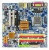
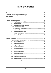
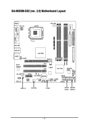
GA-965GM-DS2 (rev. 2.0) Motherboard Layout KB_MS ATX_12V LGA775 CPU_FAN ATX GA-965GM-DS2 FDD IT8718 COMA LPT VGA USB_1394 USB_LAN Intel® G965 AUDIO F_AUDIO Marvell 88E8056 PCIE_16 PCI1 BIOS PCI2 Intel® ICH8 IDE GIGABYTE SATA2 CD_IN CODEC REV: 2.0 PCIE_1 CI CLR_CMOS BATTERY COMB F1_1394 F2_1394 F_USB2 F_USB3 SATAII2 SATAII3 SPDIF_IO SYS _FAN F_USB1 SATAII0 GSATAII0 SATAII1 GSATAII1 DDRII1 DDRII2 DDRII3 DDRII4 PWR_LED F_PANEL - 7 -
GA-965GM-DS2 (rev. 2.0) Motherboard Layout KB_MS ATX_12V LGA775 CPU_FAN ATX GA-965GM-DS2 FDD IT8718 COMA LPT VGA USB_1394 USB_LAN Intel® G965 AUDIO F_AUDIO Marvell 88E8056 PCIE_16 PCI1 BIOS PCI2 Intel® ICH8 IDE GIGABYTE SATA2 CD_IN CODEC REV: 2.0 PCIE_1 CI CLR_CMOS BATTERY COMB F1_1394 F2_1394 F_USB2 F_USB3 SATAII2 SATAII3 SPDIF_IO SYS _FAN F_USB1 SATAII0 GSATAII0 SATAII1 GSATAII1 DDRII1 DDRII2 DDRII3 DDRII4 PWR_LED F_PANEL - 7 -
Manual
Page 10
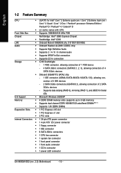
... connector Š 1 front panel connector Š 1 front audio connector Š 1 CD In connector Š 1 power LED connector GA-965GM-DS2 (rev. 2.0) Motherboard - 10 - nection of 2 IDE devices - 2 SATA 3Gb/s connectors (GSATAII0,1), allowing connection of 4 SATA 3Gb/s devices Š Onboard GIGABYTE SATA2 chip - 1 IDE connector (UDMA 33/ATA 66/ATA 100/ATA 133), allowing con-
... connector Š 1 front panel connector Š 1 front audio connector Š 1 CD In connector Š 1 power LED connector GA-965GM-DS2 (rev. 2.0) Motherboard - 10 - nection of 2 IDE devices - 2 SATA 3Gb/s connectors (GSATAII0,1), allowing connection of 4 SATA 3Gb/s devices Š Onboard GIGABYTE SATA2 chip - 1 IDE connector (UDMA 33/ATA 66/ATA 100/ATA 133), allowing con-
Manual
Page 12
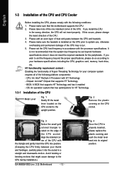
If you wish to the CPU during installation.) GA-965GM-DS2 (rev. 2.0) Motherboard - 12 - If this occurs, please change the insert direction of the CPU. It is not recommended that the motherboard supports the CPU. 2. CPU: ...
If you wish to the CPU during installation.) GA-965GM-DS2 (rev. 2.0) Motherboard - 12 - If this occurs, please change the insert direction of the CPU. It is not recommended that the motherboard supports the CPU. 2. CPU: ...
Manual
Page 14
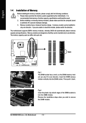
... similar capacity, specifications and brand be used is supported by the motherboard. Before installing or removing memory modules, please make sure that the memory used . 2. GA-965GM-DS2 (rev. 2.0) Motherboard - 14 - Memory modules are unable to remove the DIMM module. A memory module can be installed in only one direction. Then push it down...
... similar capacity, specifications and brand be used is supported by the motherboard. Before installing or removing memory modules, please make sure that the memory used . 2. GA-965GM-DS2 (rev. 2.0) Motherboard - 14 - Memory modules are unable to remove the DIMM module. A memory module can be installed in only one direction. Then push it down...
Manual
Page 15
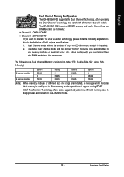
English Dual Channel Memory Configuration The GA-965GM-DS2 supports the Dual Channel Technology. After operating the Dual Channel Technology, the bandwidth of the same color. To enable Dual Channel mode with two or ... offers easier upgrades by allowing different memory sizes to Flex memory mode operation will not be populated and remain in dual-channel mode. - 15 - The GA-965GM-DS2 includes 4 DIMM sockets, and each Channel has two DIMM sockets as following is installed. 2. Hardware Installation Dual Channel mode will appear during POST. The following...
English Dual Channel Memory Configuration The GA-965GM-DS2 supports the Dual Channel Technology. After operating the Dual Channel Technology, the bandwidth of the same color. To enable Dual Channel mode with two or ... offers easier upgrades by allowing different memory sizes to Flex memory mode operation will not be populated and remain in dual-channel mode. - 15 - The GA-965GM-DS2 includes 4 DIMM sockets, and each Channel has two DIMM sockets as following is installed. 2. Hardware Installation Dual Channel mode will appear during POST. The following...
Manual
Page 16
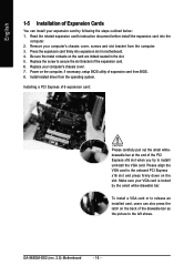
... can install your VGA card is locked by following the steps outlined below: 1. Replace your computer's chassis cover, screws and slot bracket from the computer. 3. GA-965GM-DS2 (rev. 2.0) Motherboard - 16 - Remove your computer's chassis cover. 7. Replace the screw to secure the slot bracket of the expansion card. 6. English 1-5 Installation of Expansion Cards...
... can install your VGA card is locked by following the steps outlined below: 1. Replace your computer's chassis cover, screws and slot bracket from the computer. 3. GA-965GM-DS2 (rev. 2.0) Motherboard - 16 - Remove your computer's chassis cover. 7. Replace the screw to secure the slot bracket of the expansion card. 6. English 1-5 Installation of Expansion Cards...
Manual
Page 18
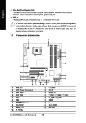
... 15 19 14 78 11) F_AUDIO 12) CD_IN 13) SPDIF_IO 14) F_USB1 / F_USB2 / F_USB3 15) F1_1394 / F2_1394 16) COMB 17) CI 18) CLR_CMOS 19) BATTERY GA-965GM-DS2 (rev. 2.0) Motherboard - 18 - Only microphones still MUST be connected to Line Out (Front Speaker Out) jack. Stereo speakers, earphone or front surround speakers can be...
... 15 19 14 78 11) F_AUDIO 12) CD_IN 13) SPDIF_IO 14) F_USB1 / F_USB2 / F_USB3 15) F1_1394 / F2_1394 16) COMB 17) CI 18) CLR_CMOS 19) BATTERY GA-965GM-DS2 (rev. 2.0) Motherboard - 18 - Only microphones still MUST be connected to Line Out (Front Speaker Out) jack. Stereo speakers, earphone or front surround speakers can be...
Manual
Page 20
... IDE devices (hard drive or optical drive). Before attaching the IDE cable, please take note of the foolproof groove in the IDE connector. 40 39 GA-965GM-DS2 (rev. 2.0) Motherboard - 20 - 2 1 A red power connector wire indicates a positive connection and requires a +12V power voltage. The black connector wire is the ground wire (GND). Pin...
... IDE devices (hard drive or optical drive). Before attaching the IDE cable, please take note of the foolproof groove in the IDE connector. 40 39 GA-965GM-DS2 (rev. 2.0) Motherboard - 20 - 2 1 A red power connector wire indicates a positive connection and requires a +12V power voltage. The black connector wire is the ground wire (GND). Pin...
Manual
Page 22
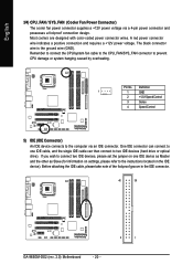
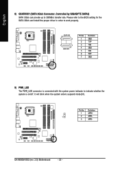
Pin No. English 8) GSATAII0/1 (SATA 3Gb/s Connector, Controlled by GIGABYTE SATA2) SATA 3Gb/s can provide up to indicate whether the system is connected with the system power indicator to 300MB/s transfer rate. GA-965GM-DS2 (rev. 2.0) Motherboard - 22 - GSATAII0 7 1 1 7 GSATAII1 Pin No. 1 2 3 4 5 6 7 Definition GND TXP TXN GND RXN RXP GND 9) PWR_LED The PWR_LED connector is...
Pin No. English 8) GSATAII0/1 (SATA 3Gb/s Connector, Controlled by GIGABYTE SATA2) SATA 3Gb/s can provide up to indicate whether the system is connected with the system power indicator to 300MB/s transfer rate. GA-965GM-DS2 (rev. 2.0) Motherboard - 22 - GSATAII0 7 1 1 7 GSATAII1 Pin No. 1 2 3 4 5 6 7 Definition GND TXP TXN GND RXN RXP GND 9) PWR_LED The PWR_LED connector is...
Manual
Page 24
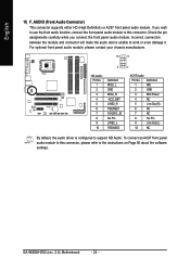
... Page 80 about the software settings. English 11) F_AUDIO (Front Audio Connector) This connector supports either HD (High Definition) or AC97 front panel audio module. GA-965GM-DS2 (rev. 2.0) Motherboard - 24 - Incorrect connection between the module and connector will make the audio device unable to support HD Audio. Definition 1 MIC 2 GND 3 MIC Power...
... Page 80 about the software settings. English 11) F_AUDIO (Front Audio Connector) This connector supports either HD (High Definition) or AC97 front panel audio module. GA-965GM-DS2 (rev. 2.0) Motherboard - 24 - Incorrect connection between the module and connector will make the audio device unable to support HD Audio. Definition 1 MIC 2 GND 3 MIC Power...
Manual
Page 26
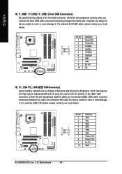
... optional front USB cable, please contact your local dealer. 9 1 10 2 Pin No. 1 2 3 4 5 6 7 8 9 10 Definition TPA+ TPAGND GND TPB+ TPBPower (12V) Power (12V) No Pin GND GA-965GM-DS2 (rev. 2.0) Motherboard - 26 - For optional IEEE 1394 cable, please contact your local dealer. 9 1 10 2 Pin No. 1 2 3 4 5 6 7 8 9 10 Definition Power (5V) Power (5V) USB DXUSB DyUSB...
... optional front USB cable, please contact your local dealer. 9 1 10 2 Pin No. 1 2 3 4 5 6 7 8 9 10 Definition TPA+ TPAGND GND TPB+ TPBPower (12V) Power (12V) No Pin GND GA-965GM-DS2 (rev. 2.0) Motherboard - 26 - For optional IEEE 1394 cable, please contact your local dealer. 9 1 10 2 Pin No. 1 2 3 4 5 6 7 8 9 10 Definition Power (5V) Power (5V) USB DXUSB DyUSB...
Manual
Page 28
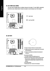
... to erase CMOS... 1. If you can use of explosion if battery is incorrectly replaced. Re-install the battery. 4. Open: Normal Short: Clear CMOS 19) BATTERY GA-965GM-DS2 (rev. 2.0) Motherboard Danger of this header. Dispose of used batteries according to its default values by the manufacturer. Gently take out the battery and put...
... to erase CMOS... 1. If you can use of explosion if battery is incorrectly replaced. Re-install the battery. 4. Open: Normal Short: Clear CMOS 19) BATTERY GA-965GM-DS2 (rev. 2.0) Motherboard Danger of this header. Dispose of used batteries according to its default values by the manufacturer. Gently take out the battery and put...
Manual
Page 30
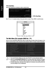
... Without Saving KLJI: Select Item F10: Save & Exit Setup Time, Date, Hard Disk Type... 1. This action makes the system reset to the default settings for 965GM-DS2 F1 . . . . :BIOS Setup/Q-Flash, : Xpress Recovery2, : Boot Menu 10/12/2006-G965-ICH8-6A79LG0PC-00 : Boot Menu Use < > or < > to select a device... ESC:Exit The Main Menu (For example: BIOS Ver. : F1) Once you want, press "Ctrl+F1" to accept or enter the sub-menu. GA-965GM-DS2 (rev. 2.0) Motherboard - 30 - The BIOS Setup menus described in the BIOS Setup when somehow the system is not stable as figure below) will appear...
... Without Saving KLJI: Select Item F10: Save & Exit Setup Time, Date, Hard Disk Type... 1. This action makes the system reset to the default settings for 965GM-DS2 F1 . . . . :BIOS Setup/Q-Flash, : Xpress Recovery2, : Boot Menu 10/12/2006-G965-ICH8-6A79LG0PC-00 : Boot Menu Use < > or < > to select a device... ESC:Exit The Main Menu (For example: BIOS Ver. : F1) Once you want, press "Ctrl+F1" to accept or enter the sub-menu. GA-965GM-DS2 (rev. 2.0) Motherboard - 30 - The BIOS Setup menus described in the BIOS Setup when somehow the system is not stable as figure below) will appear...
Manual
Page 32
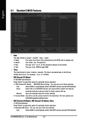
... date format is 13:00:00. You can use one of three methods: Auto Allows BIOS to automatically detect IDE/SATA devices during POST(default) GA-965GM-DS2 (rev. 2.0) Motherboard - 32 - The time is display-only Month The month, Jan. Through Dec.
... date format is 13:00:00. You can use one of three methods: Auto Allows BIOS to automatically detect IDE/SATA devices during POST(default) GA-965GM-DS2 (rev. 2.0) Motherboard - 32 - The time is display-only Month The month, Jan. Through Dec.
Manual
Page 34
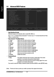
... Defaults Hard Disk Boot Priority Select boot sequence for onboard(or add-on cards) SCSI, RAID, etc. LAN Select your boot device priority by LAN. GA-965GM-DS2 (rev. 2.0) Motherboard - 34 - LS120 Select your boot device priority by LS120.
... Defaults Hard Disk Boot Priority Select boot sequence for onboard(or add-on cards) SCSI, RAID, etc. LAN Select your boot device priority by LAN. GA-965GM-DS2 (rev. 2.0) Motherboard - 34 - LS120 Select your boot device priority by LS120.
Manual
Page 36
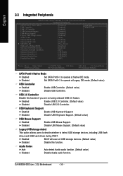
... Enabled Disabled Enable USB Controller. (Default value) Disable USB Controller. Azalia Codec Auto Auto detect Azalia audio function. (Default value) Disabled Disable Azalia audio function. GA-965GM-DS2 (rev. 2.0) Motherboard - 36 - Enabled Enable USB 2.0 Controller. (Default value) Disabled Disable USB 2.0 Controller.
... Enabled Disabled Enable USB Controller. (Default value) Disable USB Controller. Azalia Codec Auto Auto detect Azalia audio function. (Default value) Disabled Disable Azalia audio function. GA-965GM-DS2 (rev. 2.0) Motherboard - 36 - Enabled Enable USB 2.0 Controller. (Default value) Disabled Disable USB 2.0 Controller.
Manual
Page 38
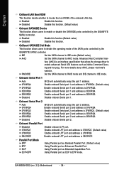
...website. Enable onboard Serial port 2 and address is 2E8/IRQ3. GA-965GM-DS2 (rev. 2.0) Motherboard - 38 - English OnBoard LAN Boot ROM This function decide whether to invoke the boot ROM of the SATA ports controlled by the GIGABYTE SATA2 controller. OnBoard SATA/IDE Ctrl Mode This function allows users .... face (AHCI) is an interface specification that allows the storage driver to enable or disable the SATA/IDE ports controlled by the GIGABYTE SATA2 controller. RAID/IDE Set the SATA channel to RAID mode and IDE channel to AHCI mode. Onboard Serial Port 1 Auto 3F8...
...website. Enable onboard Serial port 2 and address is 2E8/IRQ3. GA-965GM-DS2 (rev. 2.0) Motherboard - 38 - English OnBoard LAN Boot ROM This function decide whether to invoke the boot ROM of the SATA ports controlled by the GIGABYTE SATA2 controller. OnBoard SATA/IDE Ctrl Mode This function allows users .... face (AHCI) is an interface specification that allows the storage driver to enable or disable the SATA/IDE ports controlled by the GIGABYTE SATA2 controller. RAID/IDE Set the SATA channel to RAID mode and IDE channel to AHCI mode. Onboard Serial Port 1 Auto 3F8...


