Manual
Page 10
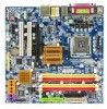
...Express x16 slot Š 1 PCI Express x1 slot Š 2 PCI slots Internal Connectors Š 1 24-pin ATX power connector Š 1 4-pin ATX 12V power connector Š 1 floppy connector Š 1 IDE connector Š 6 SATA 3Gb/s connectors Š 1 CPU fan connector Š 1 system fan connector Š 1 front panel connector Š 1 front audio connector Š 1 CD In connector Š 1 power LED connector GA-965GM-DS2 (rev. 2.0) Motherboard - 10 - Supports data striping (RAID 0), mirroring (RAID 1), and JBOD for Intel® CoreTM 2 Extreme quad-core / CoreTM 2 Extreme dual...
...Express x16 slot Š 1 PCI Express x1 slot Š 2 PCI slots Internal Connectors Š 1 24-pin ATX power connector Š 1 4-pin ATX 12V power connector Š 1 floppy connector Š 1 IDE connector Š 6 SATA 3Gb/s connectors Š 1 CPU fan connector Š 1 system fan connector Š 1 front panel connector Š 1 front audio connector Š 1 CD In connector Š 1 power LED connector GA-965GM-DS2 (rev. 2.0) Motherboard - 10 - Supports data striping (RAID 0), mirroring (RAID 1), and JBOD for Intel® CoreTM 2 Extreme quad-core / CoreTM 2 Extreme dual...
Manual
Page 13
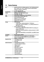
... removing the CPU cooler. - 13 - Fig. 6 Finally, please attach the power connector of motherboard after installing. Fig. 4 Please make sure the push pins aim to the CPU cooler installation section of the user manual) Fig. 5 Please check the back of the CPU cooler to the CPU as the picture, the installation is suggested that either thermal tape rather than heat paste be used for detailed installation instructions...
... removing the CPU cooler. - 13 - Fig. 6 Finally, please attach the power connector of motherboard after installing. Fig. 4 Please make sure the push pins aim to the CPU cooler installation section of the user manual) Fig. 5 Please check the back of the CPU cooler to the CPU as the picture, the installation is suggested that either thermal tape rather than heat paste be used for detailed installation instructions...
Manual
Page 18
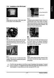
... connected to MIC In jack. channel audio setup steps for detailed software configuration information. 1-7 Connectors Introduction 1 3 2 6 5 11 18 12 10 13 17 9 16 4 1) ATX_12V 2) ATX (Power Connector) 3) CPU_FAN 4) SYS_FAN 5) IDE 6) FDD 7) SATAII0 / 1 / 2 / 3 8) GSATAII0/1 9) PWR_LED 10) F_PANEL 15 19 14 78 11) F_AUDIO 12) CD_IN 13) SPDIF_IO 14) F_USB1 / F_USB2 / F_USB3 15) F1_1394 / F2_1394 16) COMB 17) CI 18) CLR_CMOS 19) BATTERY GA-965GM-DS2 (rev. 2.0) Motherboard...
... connected to MIC In jack. channel audio setup steps for detailed software configuration information. 1-7 Connectors Introduction 1 3 2 6 5 11 18 12 10 13 17 9 16 4 1) ATX_12V 2) ATX (Power Connector) 3) CPU_FAN 4) SYS_FAN 5) IDE 6) FDD 7) SATAII0 / 1 / 2 / 3 8) GSATAII0/1 9) PWR_LED 10) F_PANEL 15 19 14 78 11) F_AUDIO 12) CD_IN 13) SPDIF_IO 14) F_USB1 / F_USB2 / F_USB3 15) F1_1394 / F2_1394 16) COMB 17) CI 18) CLR_CMOS 19) BATTERY GA-965GM-DS2 (rev. 2.0) Motherboard...
Manual
Page 20
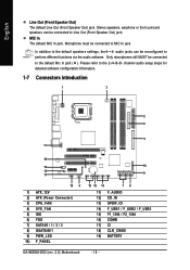
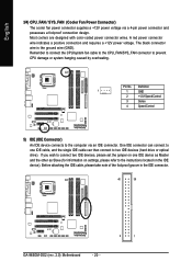
... connect the CPU/system fan cable to the CPU_FAN/SYS_FAN connector to the computer via a 4-pin power connector and possesses a foolproof connection design. The black connector wire is the ground wire (GND). English 3/4) CPU_FAN / SYS_FAN (Cooler Fan Power Connector) The cooler fan power connector supplies a +12V power voltage via an IDE connector. Most coolers are designed with color-coded power connector wires. Before attaching the IDE cable, please take note of the foolproof groove in the IDE connector. 40 39 GA-965GM-DS2 (rev. 2.0) Motherboard...
... connect the CPU/system fan cable to the CPU_FAN/SYS_FAN connector to the computer via a 4-pin power connector and possesses a foolproof connection design. The black connector wire is the ground wire (GND). English 3/4) CPU_FAN / SYS_FAN (Cooler Fan Power Connector) The cooler fan power connector supplies a +12V power voltage via an IDE connector. Most coolers are designed with color-coded power connector wires. Before attaching the IDE cable, please take note of the foolproof groove in the IDE connector. 40 39 GA-965GM-DS2 (rev. 2.0) Motherboard...
Manual
Page 21
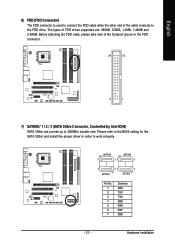
... 2 1 7) SATAII0 / 1 / 2 / 3 (SATA 3Gb/s Connector, Controlled by Intel ICH8) SATA 3Gb/s can provide up to 300MB/s transfer rate. The types of the foolproof groove in order to the FDD drive. Hardware Installation Before attaching the FDD cable, please take note of FDD drives supported are: 360KB, 720KB, 1.2MB, 1.44MB and 2.88MB. English 6) FDD (FDD Connector) The FDD connector is used to connect the FDD cable while...
... 2 1 7) SATAII0 / 1 / 2 / 3 (SATA 3Gb/s Connector, Controlled by Intel ICH8) SATA 3Gb/s can provide up to 300MB/s transfer rate. The types of the foolproof groove in order to the FDD drive. Hardware Installation Before attaching the FDD cable, please take note of FDD drives supported are: 360KB, 720KB, 1.2MB, 1.44MB and 2.88MB. English 6) FDD (FDD Connector) The FDD connector is used to connect the FDD cable while...
Manual
Page 22
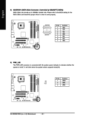
... the BIOS setting for the SATA 3Gb/s and install the proper driver in order to indicate whether the system is on/off. Definition 1 MPD+ 1 2 MPD- 3 MPD- GSATAII0 7 1 1 7 GSATAII1 Pin No. 1 2 3 4 5 6 7 Definition GND TXP TXN GND RXN RXP GND 9) PWR_LED The PWR_LED connector is connected with the system power indicator to work properly. GA-965GM-DS2 (rev. 2.0) Motherboard - 22 - English 8) GSATAII0/1 (SATA 3Gb/s Connector, Controlled by GIGABYTE SATA2) SATA 3Gb...
... the BIOS setting for the SATA 3Gb/s and install the proper driver in order to indicate whether the system is on/off. Definition 1 MPD+ 1 2 MPD- 3 MPD- GSATAII0 7 1 1 7 GSATAII1 Pin No. 1 2 3 4 5 6 7 Definition GND TXP TXN GND RXN RXP GND 9) PWR_LED The PWR_LED connector is connected with the system power indicator to work properly. GA-965GM-DS2 (rev. 2.0) Motherboard - 22 - English 8) GSATAII0/1 (SATA 3Gb/s Connector, Controlled by GIGABYTE SATA2) SATA 3Gb...
Manual
Page 32
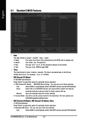
.../Auto(default:Auto) IDE Channel 2/3 Master, IDE Channel 4/5 Master, Slave IDE Auto-Detection Press "Enter" to set the access mode for faster system start up. Extended IDE Drive. For example, 1 p.m. IDE Channel 0/1 Master IDE/SATA Device Setup. Through Dec. The time is 13:00:00. You can use one of the two methods: Auto Allows BIOS to Sat, determined by the BIOS and is , , , . You can use one of three methods: Auto Allows BIOS to automatically detect IDE/SATA devices during POST(default) GA-965GM-DS2 (rev. 2.0) Motherboard...
.../Auto(default:Auto) IDE Channel 2/3 Master, IDE Channel 4/5 Master, Slave IDE Auto-Detection Press "Enter" to set the access mode for faster system start up. Extended IDE Drive. For example, 1 p.m. IDE Channel 0/1 Master IDE/SATA Device Setup. Through Dec. The time is 13:00:00. You can use one of the two methods: Auto Allows BIOS to Sat, determined by the BIOS and is , , , . You can use one of three methods: Auto Allows BIOS to automatically detect IDE/SATA devices during POST(default) GA-965GM-DS2 (rev. 2.0) Motherboard...
Manual
Page 35
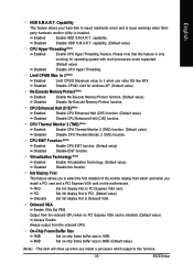
.... - 35 - Virtualization Technology (Note) Enabled Enable Virtualization Technology. (Default value) Disabled Disable this feature is installed. Limit CPUID Max. Enabled Enable HDD S.M.A.R.T. Please note that this function. Init Display First This feature allows you install a processor which card when you install a PCI card and a PCI Express VGA card on -chip frame buffer size to 8MB. (Default value) (Note) This item will show up when you to 1MB. 8MB Set on the motherboard. English HDD S.M.A.R.T. Capability This feature allows your hard disk to report...
.... - 35 - Virtualization Technology (Note) Enabled Enable Virtualization Technology. (Default value) Disabled Disable this feature is installed. Limit CPUID Max. Enabled Enable HDD S.M.A.R.T. Please note that this function. Init Display First This feature allows you install a processor which card when you install a PCI card and a PCI Express VGA card on -chip frame buffer size to 8MB. (Default value) (Note) This item will show up when you to 1MB. 8MB Set on the motherboard. English HDD S.M.A.R.T. Capability This feature allows your hard disk to report...
Manual
Page 36
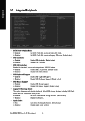
English 2-3 Integrated Peripherals CMOS Setup Utility-Copyright (C) 1984-2006 Award Software Integrated Peripherals SATA Port0-3 Native Mode USB Controller USB 2.0 Controller USB Keyboard Support USB Mouse Support Legacy USB storage detect Azalia Codec Onboard H/W 1394 Onboard H/W LAN ` SMART LAN OnBoard LAN Boot ROM Onboard SATA/IDE Device Onboard SATA/IDE Ctrl Mode Onboard Serial Port 1 Onboard Serial Port 2 Onboard Parallel Port Parallel Port Mode [Disabled] [Enabled] [Enabled] [Disabled] [Disabled] [Enabled] [Auto] [Enabled] [Enabled] [Press Enter] [Disabled] [Enabled] [IDE] [3F8/IRQ4]...
English 2-3 Integrated Peripherals CMOS Setup Utility-Copyright (C) 1984-2006 Award Software Integrated Peripherals SATA Port0-3 Native Mode USB Controller USB 2.0 Controller USB Keyboard Support USB Mouse Support Legacy USB storage detect Azalia Codec Onboard H/W 1394 Onboard H/W LAN ` SMART LAN OnBoard LAN Boot ROM Onboard SATA/IDE Device Onboard SATA/IDE Ctrl Mode Onboard Serial Port 1 Onboard Serial Port 2 Onboard Parallel Port Parallel Port Mode [Disabled] [Enabled] [Enabled] [Disabled] [Disabled] [Enabled] [Auto] [Enabled] [Enabled] [Press Enter] [Disabled] [Enabled] [IDE] [3F8/IRQ4]...
Manual
Page 38
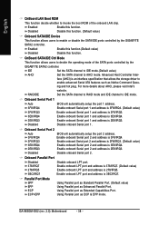
... mode. Using Parallel port as Native Command Queu- GA-965GM-DS2 (rev. 2.0) Motherboard - 38 - English OnBoard LAN Boot ROM This function decide whether to invoke the boot ROM of the SATA ports controlled by the GIGABYTE SATA2 controller. face (AHCI) is 278/IRQ5. Onboard Serial Port 2 Auto 3F8/IRQ4 2F8/IRQ3 3E8/IRQ4 2E8/IRQ3 Disabled BIOS will automatically setup the port 1 address. Onboard Parallel Port Disabled 378/IRQ7 278/IRQ5 3BC/IRQ7 Disable onboard LPT port. Enable onboard LPT port and address is 2E8/IRQ3. Enabled Enable...
... mode. Using Parallel port as Native Command Queu- GA-965GM-DS2 (rev. 2.0) Motherboard - 38 - English OnBoard LAN Boot ROM This function decide whether to invoke the boot ROM of the SATA ports controlled by the GIGABYTE SATA2 controller. face (AHCI) is 278/IRQ5. Onboard Serial Port 2 Auto 3F8/IRQ4 2F8/IRQ3 3E8/IRQ4 2E8/IRQ3 Disabled BIOS will automatically setup the port 1 address. Onboard Parallel Port Disabled 378/IRQ7 278/IRQ5 3BC/IRQ7 Disable onboard LPT port. Enable onboard LPT port and address is 2E8/IRQ3. Enabled Enable...
Manual
Page 45
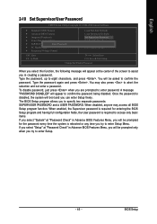
...2-10 Set Supervisor/User Password CMOS Setup Utility-Copyright (C) 1984-2006 Award Software ` Standard CMOS Features ` Advanced BIOS Features ` Integrated Peripherals ` Power Management Setup ` PnP/PCI ConfigurationEsnter Password: ` PC Health Status ` Frequency/Voltage Control Load Fail-Safe Defaults Load Optimized Defaults Set Supervisor Password Set User Password Save & Exit Setup Exit Without Saving ESC: Quit F8: Q-Flash KLJI: Select Item F10: Save & Exit Setup Change/Set/Disable Password When you select this function, the following message will appear at the center of the screen to...
...2-10 Set Supervisor/User Password CMOS Setup Utility-Copyright (C) 1984-2006 Award Software ` Standard CMOS Features ` Advanced BIOS Features ` Integrated Peripherals ` Power Management Setup ` PnP/PCI ConfigurationEsnter Password: ` PC Health Status ` Frequency/Voltage Control Load Fail-Safe Defaults Load Optimized Defaults Set Supervisor Password Set User Password Save & Exit Setup Exit Without Saving ESC: Quit F8: Q-Flash KLJI: Select Item F10: Save & Exit Setup Change/Set/Disable Password When you select this function, the following message will appear at the center of the screen to...
Manual
Page 52
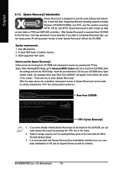
... Xpress Recovery2 be made by pressing the F9 key: Steps: After entering BIOS Setup, go to Advanced BIOS Feature and set to run Xpress Recovery2 later, you complete installations of the screen. Insert the provided driver CD into your hard disk. Award Modular BIOS v6.00PG, An Energy Star Ally Copyright (C) 1984-2006, Award Software, Inc. GA-965GM-DS2 (rev. 2.0) Motherboard - 52 - After the steps above are completed, subsequent...
... Xpress Recovery2 be made by pressing the F9 key: Steps: After entering BIOS Setup, go to Advanced BIOS Feature and set to run Xpress Recovery2 later, you complete installations of the screen. Insert the provided driver CD into your hard disk. Award Modular BIOS v6.00PG, An Energy Star Ally Copyright (C) 1984-2006, Award Software, Inc. GA-965GM-DS2 (rev. 2.0) Motherboard - 52 - After the steps above are completed, subsequent...
Manual
Page 55
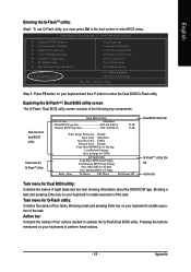
...your keyboards to enter the Dual BIOS/Q-Flash utility. Task menu for Dual BIOS utility Task menu for Q-FlashTM utility Dual BIOS Utility Boot From Main Bios Main ROM Type/Size SST 49LF003A Backup ROM Type/Size SST 49LF003A 512K 512K Wide Range Protection Disable Boot From Main Bios Auto Recovery Enable Halt On Error Disable Copy Main ROM Data to Backup Load Default Settings Save Settings to CMOS Q-Flash Utility Load Main BIOS from Floppy Load Backup BIOS from Floppy Save Main BIOS to Floppy Save Backup BIOS to Floppy Enter : Run :Move ESC:Reset F10:Power Off Dual BIOS utility bar...
...your keyboards to enter the Dual BIOS/Q-Flash utility. Task menu for Dual BIOS utility Task menu for Q-FlashTM utility Dual BIOS Utility Boot From Main Bios Main ROM Type/Size SST 49LF003A Backup ROM Type/Size SST 49LF003A 512K 512K Wide Range Protection Disable Boot From Main Bios Auto Recovery Enable Halt On Error Disable Copy Main ROM Data to Backup Load Default Settings Save Settings to CMOS Q-Flash Utility Load Main BIOS from Floppy Load Backup BIOS from Floppy Save Main BIOS to Floppy Save Backup BIOS to Floppy Enter : Run :Move ESC:Reset F10:Power Off Dual BIOS utility bar...
Manual
Page 63
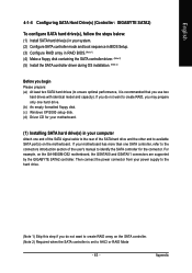
... the user's manual to ensure optimal performance, it is set to available SATA port(s) on the GA-965GM-DS2 motherboard, the GSATAII0 and GSATAII1 connectors are supported by the GIGABYTE SATA2 controller. English 4-1-4 Configuring SATA Hard Drive(s) (Controller: GIGABYTE SATA2) To configure SATA hard drive(s), follow the steps below: (1) Install SATA hard drive(s) in your system. (2) Configure SATA controller mode and boot sequence in BIOS Setup. (3) Configure RAID array in your computer Attach one SATA controller, refer to the connectors introduction section of the SATA hard drive and...
... the user's manual to ensure optimal performance, it is set to available SATA port(s) on the GA-965GM-DS2 motherboard, the GSATAII0 and GSATAII1 connectors are supported by the GIGABYTE SATA2 controller. English 4-1-4 Configuring SATA Hard Drive(s) (Controller: GIGABYTE SATA2) To configure SATA hard drive(s), follow the steps below: (1) Install SATA hard drive(s) in your system. (2) Configure SATA controller mode and boot sequence in BIOS Setup. (3) Configure RAID array in your computer Attach one SATA controller, refer to the connectors introduction section of the SATA hard drive and...
Manual
Page 64
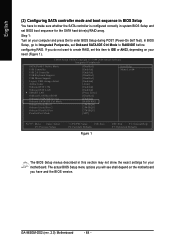
CMOS Setup Utility-Copyright (C) 1984-2006 Award Software Integrated Peripherals SATA Port0-3 Native Mode USB Controller USB 2.0 Controller USB Keyboard Support USB Mouse Support Legacy USB storage detect Azalia Codec Onboard H/W 1394 Onboard H/W LAN SMART LAN OnBoard LAN Boot ROM Onboard SATA/IDE Device Onboard SATA/IDE Ctrl Mode Onboard Serial Port 1 Onboard Serial Port 2 Onboard Parallel Port Parallel Port Mode [Disabled] [Enabled] [Enabled] [Disabled] [Disabled] [Enabled] [Auto] [Enabled] [Enabled] [Press Enter] [Disabled] [Enabled] [RAID/IDE] [3F8/IRQ4] [2F8/IRQ3] [378/IRQ7] [SPP] Item...
CMOS Setup Utility-Copyright (C) 1984-2006 Award Software Integrated Peripherals SATA Port0-3 Native Mode USB Controller USB 2.0 Controller USB Keyboard Support USB Mouse Support Legacy USB storage detect Azalia Codec Onboard H/W 1394 Onboard H/W LAN SMART LAN OnBoard LAN Boot ROM Onboard SATA/IDE Device Onboard SATA/IDE Ctrl Mode Onboard Serial Port 1 Onboard Serial Port 2 Onboard Parallel Port Parallel Port Mode [Disabled] [Enabled] [Enabled] [Disabled] [Disabled] [Enabled] [Auto] [Enabled] [Enabled] [Press Enter] [Disabled] [Enabled] [RAID/IDE] [3F8/IRQ4] [2F8/IRQ3] [378/IRQ7] [SPP] Item...

Manual
Page 66
... system boot begins, look for a message which says "Press to enter the GIGABYTE SATA2 RAID BIOS setup utility. GIGA-BYTE Technology Corp. PCIE-to-SATAII/IDE RAID Controller BIOS V1.06.53 [ Main Menu ] [ Hard Disk Drive List ] Create RAID Disk Drive Delete RAID Disk Drive Revert HDD to Non-RAID Solve Mirror Conflict Rebuild Mirror Drive Save And Exit Setup Exit Without Saving Mode Name HDD0: ST3120026AS HDD1: ST3120026AS Capacity 120 GB 120 GB Type/Status Non-RAID Non-RAID [ RAID Disk Drive List ] [ TAB]-Switch Window [ ]-Select ITEM [ENTER...
... system boot begins, look for a message which says "Press to enter the GIGABYTE SATA2 RAID BIOS setup utility. GIGA-BYTE Technology Corp. PCIE-to-SATAII/IDE RAID Controller BIOS V1.06.53 [ Main Menu ] [ Hard Disk Drive List ] Create RAID Disk Drive Delete RAID Disk Drive Revert HDD to Non-RAID Solve Mirror Conflict Rebuild Mirror Drive Save And Exit Setup Exit Without Saving Mode Name HDD0: ST3120026AS HDD1: ST3120026AS Capacity 120 GB 120 GB Type/Status Non-RAID Non-RAID [ RAID Disk Drive List ] [ TAB]-Switch Window [ ]-Select ITEM [ENTER...
Manual
Page 72
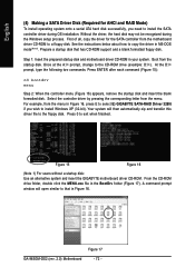
... a SATA Driver Disk (Required for the SATA controller from the motherboard driver CD-ROM to a floppy disk. Once at the A:\> prompt, change to exit when finished. Press 0 to the CD-ROM drive (example: D:\>). A command prompt window will then automatically zip and transfer this driver file to copy the driver in Figure 16, press E to select E) GIGABYTE SATA-RAID Driver 32Bit if you need to install Windows XP (32-bit). Boot from the menu. From the CD-ROM drive...
... a SATA Driver Disk (Required for the SATA controller from the motherboard driver CD-ROM to a floppy disk. Once at the A:\> prompt, change to exit when finished. Press 0 to the CD-ROM drive (example: D:\>). A command prompt window will then automatically zip and transfer this driver file to copy the driver in Figure 16, press E to select E) GIGABYTE SATA-RAID Driver 32Bit if you need to install Windows XP (32-bit). Boot from the menu. From the CD-ROM drive...
Manual
Page 73
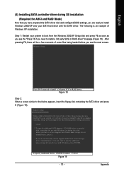
... additional mass storage devices for AHCI and RAID Mode) Now that below appears, insert the floppy disk containing the SATA driver and press S (Figure 19). Figure 18 Step 2: When a screen similar to that you have prepared the SATA driver disk and configured BIOS settings, you are ready to manually specify an adapter. English (5) Installing SATA controller driver during OS installation (Required for use with Windows, including those for which you have a device support disk from a mass storage device manufacturer...
... additional mass storage devices for AHCI and RAID Mode) Now that below appears, insert the floppy disk containing the SATA driver and press S (Figure 19). Figure 18 Step 2: When a screen similar to that you have prepared the SATA driver disk and configured BIOS settings, you are ready to manually specify an adapter. English (5) Installing SATA controller driver during OS installation (Required for use with Windows, including those for which you have a device support disk from a mass storage device manufacturer...
Manual
Page 74
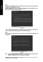
... mass storage devices for which you have a device support disk from a mass storage device manufacturer, press S. * If you do not have chosen to configure a SCSI Adapter for the following list, or press ESC to return to continue the SATA driver installation from the motherboard driver CD. GA-965GM-DS2 (rev. 2.0) Motherboard - 74 - Step 4: When the next screen (Figure 21) appears, press ENTER to the previous screen. Use the ARROW keys to select GIGABYTE GBB363 RAID Controller (Windows...
... mass storage devices for which you have a device support disk from a mass storage device manufacturer, press S. * If you do not have chosen to configure a SCSI Adapter for the following list, or press ESC to return to continue the SATA driver installation from the motherboard driver CD. GA-965GM-DS2 (rev. 2.0) Motherboard - 74 - Step 4: When the next screen (Figure 21) appears, press ENTER to the previous screen. Use the ARROW keys to select GIGABYTE GBB363 RAID Controller (Windows...
Manual
Page 81
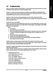
... down ? AWARD BIOS Beep Codes 1 short: System boots successfully 2 short: CMOS setting error 1 long 1 short: DRAM or M/B error 1 long 2 short: Monitor or display card error 1 long 3 short: Keyboard error 1 long 9 short: BIOS ROM error Continuous long beeps: DRAM error Continuous short beeps: Power error - 81 - What do I still get a weak sound after computer shuts down and that were included in previous BIOS after entering BIOS menu and you identify the possible computer problems. However, they are hidden in the manual. Question 3: How do these options. Answer: In...
... down ? AWARD BIOS Beep Codes 1 short: System boots successfully 2 short: CMOS setting error 1 long 1 short: DRAM or M/B error 1 long 2 short: Monitor or display card error 1 long 3 short: Keyboard error 1 long 9 short: BIOS ROM error Continuous long beeps: DRAM error Continuous short beeps: Power error - 81 - What do I still get a weak sound after computer shuts down and that were included in previous BIOS after entering BIOS menu and you identify the possible computer problems. However, they are hidden in the manual. Question 3: How do these options. Answer: In...


