Manual
Page 1
GA-965GM-DS2 (rev. 2.0) Intel® CoreTM 2 Extreme quad-core / CoreTM 2 Quad / Intel® CoreTM 2 Extreme dual-core / CoreTM 2 Duo / Intel® Pentium® Processor Extreme Edition / Intel® Pentium® D / Pentium® 4 LGA775 Processor Motherboard User's Manual Rev. 2002 12ME-965GMDR-2002R * The WEEE marking on the product indicates this product must not be disposed...
GA-965GM-DS2 (rev. 2.0) Intel® CoreTM 2 Extreme quad-core / CoreTM 2 Quad / Intel® CoreTM 2 Extreme dual-core / CoreTM 2 Duo / Intel® Pentium® Processor Extreme Edition / Intel® Pentium® D / Pentium® 4 LGA775 Processor Motherboard User's Manual Rev. 2002 12ME-965GMDR-2002R * The WEEE marking on the product indicates this product must not be disposed...
Manual
Page 2
Motherboard GA-965GM-DS2 (rev. 2.0) Oct. 1, 2006 Motherboard GA-965GM-DS2 (rev. 2.0) Oct. 1, 2006
Motherboard GA-965GM-DS2 (rev. 2.0) Oct. 1, 2006 Motherboard GA-965GM-DS2 (rev. 2.0) Oct. 1, 2006
Manual
Page 4
Table of Contents ItemChecklist ...6 OptionalAccessories ...6 GA-965GM-DS2 (rev. 2.0) Motherboard Layout 7 Block Diagram ...8 Chapter 1 Hardware Installation 9 1-1 Considerations Prior to Installation 9 1-2 Feature Summary 10 1-3 Installation of the CPU and CPU Cooler 12 1-3-1 Installation of the ...
Table of Contents ItemChecklist ...6 OptionalAccessories ...6 GA-965GM-DS2 (rev. 2.0) Motherboard Layout 7 Block Diagram ...8 Chapter 1 Hardware Installation 9 1-1 Considerations Prior to Installation 9 1-2 Feature Summary 10 1-3 Installation of the CPU and CPU Cooler 12 1-3-1 Installation of the ...
Manual
Page 7
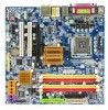
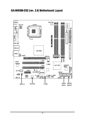
GA-965GM-DS2 (rev. 2.0) Motherboard Layout KB_MS ATX_12V LGA775 CPU_FAN ATX GA-965GM-DS2 FDD IT8718 COMA LPT VGA USB_1394 USB_LAN Intel® G965 AUDIO F_AUDIO Marvell 88E8056 PCIE_16 PCI1 BIOS PCI2 Intel® ICH8 IDE GIGABYTE SATA2 CD_IN CODEC REV: 2.0 PCIE_1 CI CLR_CMOS BATTERY COMB F1_1394 F2_1394 F_USB2 F_USB3 SATAII2 SATAII3 SPDIF_IO SYS _FAN F_USB1 SATAII0 GSATAII0 SATAII1 GSATAII1 DDRII1 DDRII2 DDRII3 DDRII4 PWR_LED F_PANEL - 7 -
GA-965GM-DS2 (rev. 2.0) Motherboard Layout KB_MS ATX_12V LGA775 CPU_FAN ATX GA-965GM-DS2 FDD IT8718 COMA LPT VGA USB_1394 USB_LAN Intel® G965 AUDIO F_AUDIO Marvell 88E8056 PCIE_16 PCI1 BIOS PCI2 Intel® ICH8 IDE GIGABYTE SATA2 CD_IN CODEC REV: 2.0 PCIE_1 CI CLR_CMOS BATTERY COMB F1_1394 F2_1394 F_USB2 F_USB3 SATAII2 SATAII3 SPDIF_IO SYS _FAN F_USB1 SATAII0 GSATAII0 SATAII1 GSATAII1 DDRII1 DDRII2 DDRII3 DDRII4 PWR_LED F_PANEL - 7 -
Manual
Page 10
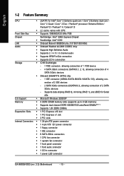
...CPU fan connector Š 1 system fan connector Š 1 front panel connector Š 1 front audio connector Š 1 CD In connector Š 1 power LED connector GA-965GM-DS2 (rev. 2.0) Motherboard - 10 - Supports data striping (RAID 0), mirroring (RAID 1), and JBOD for Intel® CoreTM 2 Extreme quad-core / CoreTM 2 Extreme dual-core / CoreTM... 3Gb/s devices - nection of 2 IDE devices - 2 SATA 3Gb/s connectors (GSATAII0,1), allowing connection of 4 SATA 3Gb/s devices Š Onboard GIGABYTE SATA2 chip - 1 IDE connector (UDMA 33/ATA 66/ATA 100/ATA 133), allowing con-
...CPU fan connector Š 1 system fan connector Š 1 front panel connector Š 1 front audio connector Š 1 CD In connector Š 1 power LED connector GA-965GM-DS2 (rev. 2.0) Motherboard - 10 - Supports data striping (RAID 0), mirroring (RAID 1), and JBOD for Intel® CoreTM 2 Extreme quad-core / CoreTM 2 Extreme dual-core / CoreTM... 3Gb/s devices - nection of 2 IDE devices - 2 SATA 3Gb/s connectors (GSATAII0,1), allowing connection of 4 SATA 3Gb/s devices Š Onboard GIGABYTE SATA2 chip - 1 IDE connector (UDMA 33/ATA 66/ATA 100/ATA 133), allowing con-
Manual
Page 12
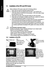
..., otherwise overheating and permanent damage of the CPU. Fig. 3 Notice the small gold colored triangle located on the CPU socket to the CPU during installation.) GA-965GM-DS2 (rev. 2.0) Motherboard - 12 - Align the indented corner of the CPU socket. CPU: An Intel® Pentium 4 Processor with the processor specifications. BIOS: A BIOS that might cause...
..., otherwise overheating and permanent damage of the CPU. Fig. 3 Notice the small gold colored triangle located on the CPU socket to the CPU during installation.) GA-965GM-DS2 (rev. 2.0) Motherboard - 12 - Align the indented corner of the CPU socket. CPU: An Intel® Pentium 4 Processor with the processor specifications. BIOS: A BIOS that might cause...
Manual
Page 14
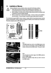
... in one direction. Then push it down. Reverse the installation steps when you are designed so that the computer power is supported by the motherboard. GA-965GM-DS2 (rev. 2.0) Motherboard - 14 - A memory module can differ with the following conditions: 1. Notch DDRII Fig.1 The DIMM socket has a notch, so the DIMM memory module can be...
... in one direction. Then push it down. Reverse the installation steps when you are designed so that the computer power is supported by the motherboard. GA-965GM-DS2 (rev. 2.0) Motherboard - 14 - A memory module can differ with the following conditions: 1. Notch DDRII Fig.1 The DIMM socket has a notch, so the DIMM memory module can be...
Manual
Page 16
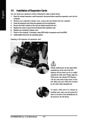
... before install the expansion card into expansion slot in the slot. 5. Please align the VGA card to secure the slot bracket of the expansion card. 6. GA-965GM-DS2 (rev. 2.0) Motherboard - 16 - Replace the screw to the onboard PCI Express x16 slot and press firmly down on the slot. Power on the computer, if necessary...
... before install the expansion card into expansion slot in the slot. 5. Please align the VGA card to secure the slot bracket of the expansion card. 6. GA-965GM-DS2 (rev. 2.0) Motherboard - 16 - Replace the screw to the onboard PCI Express x16 slot and press firmly down on the slot. Power on the computer, if necessary...
Manual
Page 18
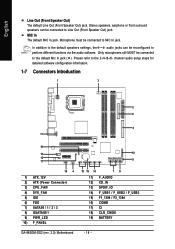
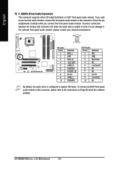
... 15 19 14 78 11) F_AUDIO 12) CD_IN 13) SPDIF_IO 14) F_USB1 / F_USB2 / F_USB3 15) F1_1394 / F2_1394 16) COMB 17) CI 18) CLR_CMOS 19) BATTERY GA-965GM-DS2 (rev. 2.0) Motherboard - 18 - Stereo speakers, earphone or front surround speakers can be connected to the 2-/4-/6-/8- Only microphones still MUST be reconfigured to perform different functions via...
... 15 19 14 78 11) F_AUDIO 12) CD_IN 13) SPDIF_IO 14) F_USB1 / F_USB2 / F_USB3 15) F1_1394 / F2_1394 16) COMB 17) CI 18) CLR_CMOS 19) BATTERY GA-965GM-DS2 (rev. 2.0) Motherboard - 18 - Stereo speakers, earphone or front surround speakers can be connected to the 2-/4-/6-/8- Only microphones still MUST be reconfigured to perform different functions via...
Manual
Page 20
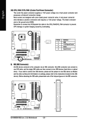
... Slave (for information on the IDE device). Before attaching the IDE cable, please take note of the foolproof groove in the IDE connector. 40 39 GA-965GM-DS2 (rev. 2.0) Motherboard - 20 - 2 1 Remember to connect the CPU/system fan cable to the CPU_FAN/SYS_FAN connector to the instructions located on settings, please refer to prevent...
... Slave (for information on the IDE device). Before attaching the IDE cable, please take note of the foolproof groove in the IDE connector. 40 39 GA-965GM-DS2 (rev. 2.0) Motherboard - 20 - 2 1 Remember to connect the CPU/system fan cable to the CPU_FAN/SYS_FAN connector to the instructions located on settings, please refer to prevent...
Manual
Page 22
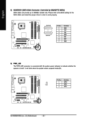
GSATAII0 7 1 1 7 GSATAII1 Pin No. 1 2 3 4 5 6 7 Definition GND TXP TXN GND RXN RXP GND 9) PWR_LED The PWR_LED connector is on/off. Pin No. GA-965GM-DS2 (rev. 2.0) Motherboard - 22 - English 8) GSATAII0/1 (SATA 3Gb/s Connector, Controlled by GIGABYTE SATA2) SATA 3Gb/s can provide up to indicate whether the system is connected with the system power indicator to 300MB/s transfer...
GSATAII0 7 1 1 7 GSATAII1 Pin No. 1 2 3 4 5 6 7 Definition GND TXP TXN GND RXN RXP GND 9) PWR_LED The PWR_LED connector is on/off. Pin No. GA-965GM-DS2 (rev. 2.0) Motherboard - 22 - English 8) GSATAII0/1 (SATA 3Gb/s Connector, Controlled by GIGABYTE SATA2) SATA 3Gb/s can provide up to indicate whether the system is connected with the system power indicator to 300MB/s transfer...
Manual
Page 24
... Power 4 NC 5 Line Out (R) 6 NC 7 NC 8 No Pin 9 Line Out (L) 10 NC By default, the audio driver is configured to work or even damage it. GA-965GM-DS2 (rev. 2.0) Motherboard - 24 - Incorrect connection between the module and connector will make the audio device unable to support HD Audio. English 11) F_AUDIO (Front Audio Connector...
... Power 4 NC 5 Line Out (R) 6 NC 7 NC 8 No Pin 9 Line Out (L) 10 NC By default, the audio driver is configured to work or even damage it. GA-965GM-DS2 (rev. 2.0) Motherboard - 24 - Incorrect connection between the module and connector will make the audio device unable to support HD Audio. English 11) F_AUDIO (Front Audio Connector...
Manual
Page 26
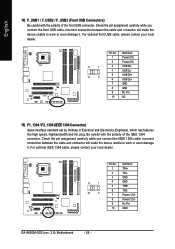
... optional front USB cable, please contact your local dealer. 9 1 10 2 Pin No. 1 2 3 4 5 6 7 8 9 10 Definition TPA+ TPAGND GND TPB+ TPBPower (12V) Power (12V) No Pin GND GA-965GM-DS2 (rev. 2.0) Motherboard - 26 - For optional IEEE 1394 cable, please contact your local dealer. 9 1 10 2 Pin No. 1 2 3 4 5 6 7 8 9 10 Definition Power (5V) Power (5V) USB DXUSB DyUSB DX...
... optional front USB cable, please contact your local dealer. 9 1 10 2 Pin No. 1 2 3 4 5 6 7 8 9 10 Definition TPA+ TPAGND GND TPB+ TPBPower (12V) Power (12V) No Pin GND GA-965GM-DS2 (rev. 2.0) Motherboard - 26 - For optional IEEE 1394 cable, please contact your local dealer. 9 1 10 2 Pin No. 1 2 3 4 5 6 7 8 9 10 Definition Power (5V) Power (5V) USB DXUSB DyUSB DX...
Manual
Page 28
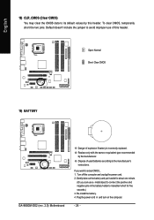
To clear CMOS, temporarily short the two pins. If you can use of this header. Open: Normal Short: Clear CMOS 19) BATTERY GA-965GM-DS2 (rev. 2.0) Motherboard Danger of used batteries according to erase CMOS... 1. Re-install the battery. 4. Default doesn't include the jumper to avoid improper use a metal object to ...
To clear CMOS, temporarily short the two pins. If you can use of this header. Open: Normal Short: Clear CMOS 19) BATTERY GA-965GM-DS2 (rev. 2.0) Motherboard Danger of used batteries according to erase CMOS... 1. Re-install the battery. 4. Default doesn't include the jumper to avoid improper use a metal object to ...
Manual
Page 30
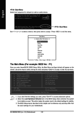
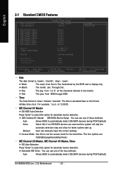
...:Exit The Main Menu (For example: BIOS Ver. : F1) Once you want, press "Ctrl+F1" to accept or enter the sub-menu. GA-965GM-DS2 (rev. 2.0) Motherboard - 30 - Select the Load Optimized Defaults item in this menu. English : Boot Menu Select boot sequence for stability. 3. Press to... exit this chapter are for reference only and may differ from the exact settings for 965GM-DS2 F1 . . . . :BIOS Setup/Q-Flash, : Xpress Recovery2, : Boot Menu 10/12/2006-G965-ICH8-6A79LG0PC-00 : Boot Menu Use < > or < ...
...:Exit The Main Menu (For example: BIOS Ver. : F1) Once you want, press "Ctrl+F1" to accept or enter the sub-menu. GA-965GM-DS2 (rev. 2.0) Motherboard - 30 - Select the Load Optimized Defaults item in this menu. English : Boot Menu Select boot sequence for stability. 3. Press to... exit this chapter are for reference only and may differ from the exact settings for 965GM-DS2 F1 . . . . :BIOS Setup/Q-Flash, : Xpress Recovery2, : Boot Menu 10/12/2006-G965-ICH8-6A79LG0PC-00 : Boot Menu Use < > or < ...
Manual
Page 32
.../Large/Auto(default:Auto) IDE Channel 2/3 Master, IDE Channel 4/5 Master, Slave IDE Auto-Detection Press "Enter" to automatically detect IDE/SATA devices during POST(default) GA-965GM-DS2 (rev. 2.0) Motherboard - 32 - Manual User can use one of three methods: Auto Allows BIOS to select this option for the hard drive. Week The week, from...
.../Large/Auto(default:Auto) IDE Channel 2/3 Master, IDE Channel 4/5 Master, Slave IDE Auto-Detection Press "Enter" to automatically detect IDE/SATA devices during POST(default) GA-965GM-DS2 (rev. 2.0) Motherboard - 32 - Manual User can use one of three methods: Auto Allows BIOS to select this option for the hard drive. Week The week, from...
Manual
Page 34
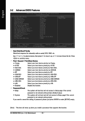
.... Disabled Disable this menu. First / Second / Third Boot Device Floppy Select your boot device priority by Floppy. CDROM Select your boot device priority by CDROM. GA-965GM-DS2 (rev. 2.0) Motherboard - 34 - Capability CPU Hyper-Threading (Note) Limit CPUID Max. LS120 Select your boot device priority by LS120. USB-FDD Select your boot device priority...
.... Disabled Disable this menu. First / Second / Third Boot Device Floppy Select your boot device priority by Floppy. CDROM Select your boot device priority by CDROM. GA-965GM-DS2 (rev. 2.0) Motherboard - 34 - Capability CPU Hyper-Threading (Note) Limit CPUID Max. LS120 Select your boot device priority by LS120. USB-FDD Select your boot device priority...
Manual
Page 36
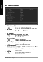
USB 2.0 Controller Disable this function. Disabled Disable USB Keyboard Support. (Default value) USB Mouse Support Enabled Disabled Enable USB Mouse Support. GA-965GM-DS2 (rev. 2.0) Motherboard - 36 - Disabled Set SATA Port0~3 to operate at Native IDE mode. Enabled BIOS will scan all USB storage devices. (Default value) Disabled Disable this ...
USB 2.0 Controller Disable this function. Disabled Disable USB Keyboard Support. (Default value) USB Mouse Support Enabled Disabled Enable USB Mouse Support. GA-965GM-DS2 (rev. 2.0) Motherboard - 36 - Disabled Set SATA Port0~3 to operate at Native IDE mode. Enabled BIOS will scan all USB storage devices. (Default value) Disabled Disable this ...
Manual
Page 38
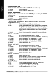
...Port. face (AHCI) is an interface specification that allows the storage driver to enable or disable the SATA/IDE ports controlled by the GIGABYTE SATA2 controller. Enable onboard Serial port 1 and address is 3F8/IRQ4. (Default value) 2F8/IRQ3 Enable onboard Serial port 1 and ...invoke the boot ROM of the SATA ports controlled by the GIGABYTE SATA2 controller. Onboard Parallel Port Disabled 378/IRQ7 278/IRQ5 3BC/IRQ7 Disable onboard LPT port. Enable onboard LPT port and address is 278/IRQ5. GA-965GM-DS2 (rev. 2.0) Motherboard - 38 - Enabled Disabled Enable this function....
...Port. face (AHCI) is an interface specification that allows the storage driver to enable or disable the SATA/IDE ports controlled by the GIGABYTE SATA2 controller. Enable onboard Serial port 1 and address is 3F8/IRQ4. (Default value) 2F8/IRQ3 Enable onboard Serial port 1 and ...invoke the boot ROM of the SATA ports controlled by the GIGABYTE SATA2 controller. Onboard Parallel Port Disabled 378/IRQ7 278/IRQ5 3BC/IRQ7 Disable onboard LPT port. Enable onboard LPT port and address is 278/IRQ5. GA-965GM-DS2 (rev. 2.0) Motherboard - 38 - Enabled Disabled Enable this function....
Manual
Page 40
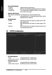
When AC-power back to the system, the system will be in "On" Memory state. GA-965GM-DS2 (rev. 2.0) Motherboard - 40 - Enter Input password (from 1 to 5 characters to power on the system. AC Back Function Soft-Off When AC-power back to the system, ...
When AC-power back to the system, the system will be in "On" Memory state. GA-965GM-DS2 (rev. 2.0) Motherboard - 40 - Enter Input password (from 1 to 5 characters to power on the system. AC Back Function Soft-Off When AC-power back to the system, ...


