Manual
Page 4
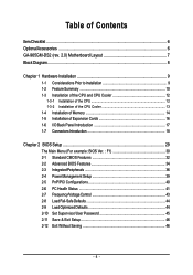
Table of Contents ItemChecklist ...6 OptionalAccessories ...6 GA-965GM-DS2 (rev. 2.0) Motherboard Layout 7 Block Diagram ...8 Chapter 1 Hardware Installation 9 1-1 Considerations Prior to Installation 9 1-2 Feature Summary 10 1-3 Installation of ... 1-5 Installation of Expansion Cards 16 1-6 I/O Back Panel Introduction 17 1-7 Connectors Introduction 18 Chapter 2 BIOS Setup 29 The Main Menu (For example: BIOS Ver. : F1 30 2-1 Standard CMOS Features 32 2-2 Advanced BIOS Features 34 2-3 IntegratedPeripherals 36 2-4 Power Management Setup 39 2-5 PnP/PCI Configurations 40 2-6 PC Health ...
Table of Contents ItemChecklist ...6 OptionalAccessories ...6 GA-965GM-DS2 (rev. 2.0) Motherboard Layout 7 Block Diagram ...8 Chapter 1 Hardware Installation 9 1-1 Considerations Prior to Installation 9 1-2 Feature Summary 10 1-3 Installation of ... 1-5 Installation of Expansion Cards 16 1-6 I/O Back Panel Introduction 17 1-7 Connectors Introduction 18 Chapter 2 BIOS Setup 29 The Main Menu (For example: BIOS Ver. : F1 30 2-1 Standard CMOS Features 32 2-2 Advanced BIOS Features 34 2-3 IntegratedPeripherals 36 2-4 Power Management Setup 39 2-5 PnP/PCI Configurations 40 2-6 PC Health ...

Manual
Page 5
Channel Audio Function Introduction 76 4-2 Troubleshooting 81 - 5 - Chapter 3 Install Drivers 47 3-1 Install Chipset Drivers 47 3-2 SoftwareApplications 48 3-3 Driver CD Information 48 3-4 Hardware Information 49 3-5 Contact Us ...49 Chapter 4 Appendix 51 4-1 Unique Software Utilities 51 4-1-1 EasyTune 5 Introduction 51 4-1-2 Xpress Recovery2 Introduction 52 4-1-3 Flash BIOS Method Introduction 54 4-1-4 Configuring SATA Hard Drive(s) (Controller: GIGABYTE SATA2 63 4-1-5 2- / 4- / 6- / 8-
Channel Audio Function Introduction 76 4-2 Troubleshooting 81 - 5 - Chapter 3 Install Drivers 47 3-1 Install Chipset Drivers 47 3-2 SoftwareApplications 48 3-3 Driver CD Information 48 3-4 Hardware Information 49 3-5 Contact Us ...49 Chapter 4 Appendix 51 4-1 Unique Software Utilities 51 4-1-1 EasyTune 5 Introduction 51 4-1-2 Xpress Recovery2 Introduction 52 4-1-3 Flash BIOS Method Introduction 54 4-1-4 Configuring SATA Hard Drive(s) (Controller: GIGABYTE SATA2 63 4-1-5 2- / 4- / 6- / 8-
Manual
Page 7
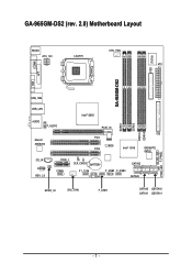
GA-965GM-DS2 (rev. 2.0) Motherboard Layout KB_MS ATX_12V LGA775 CPU_FAN ATX GA-965GM-DS2 FDD IT8718 COMA LPT VGA USB_1394 USB_LAN Intel® G965 AUDIO F_AUDIO Marvell 88E8056 PCIE_16 PCI1 BIOS PCI2 Intel® ICH8 IDE GIGABYTE SATA2 CD_IN CODEC REV: 2.0 PCIE_1 CI CLR_CMOS BATTERY COMB F1_1394 F2_1394 F_USB2 F_USB3 SATAII2 SATAII3 SPDIF_IO SYS _FAN F_USB1 SATAII0 GSATAII0 SATAII1 GSATAII1 DDRII1 DDRII2 DDRII3 DDRII4 PWR_LED F_PANEL - 7 -
GA-965GM-DS2 (rev. 2.0) Motherboard Layout KB_MS ATX_12V LGA775 CPU_FAN ATX GA-965GM-DS2 FDD IT8718 COMA LPT VGA USB_1394 USB_LAN Intel® G965 AUDIO F_AUDIO Marvell 88E8056 PCIE_16 PCI1 BIOS PCI2 Intel® ICH8 IDE GIGABYTE SATA2 CD_IN CODEC REV: 2.0 PCIE_1 CI CLR_CMOS BATTERY COMB F1_1394 F2_1394 F_USB2 F_USB3 SATAII2 SATAII3 SPDIF_IO SYS _FAN F_USB1 SATAII0 GSATAII0 SATAII1 GSATAII1 DDRII1 DDRII2 DDRII3 DDRII4 PWR_LED F_PANEL - 7 -
Manual
Page 8
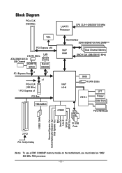
... PCIe CLK (100 MHz) LGA775 Processor CPU CLK+/-(266/200/133 MHz) VGA PCI Express x16 2 SATA 3Gb/s LAN ATA33/66/100/133 IDE Channel GIGABYTE RJ45 Marvell SATA2 88E8056 PCI Express Bus x 1 x1 x1 PCIe CLK (100 MHz) 1 PCI Express x1 PCI Bus TSB43AB23 Host Interface DDRII 800/667/533... MHz DIMM(Note) Intel® G965 Dual Channel Memory GMCH CLK (266/200/133 MHz) Intel® ICH8 CODEC BIOS 4 SATA 3Gb/s IT8718 LPT Floppy COM Ports PS/2 KB/Mouse 3 IEEE 1394a Surround Speaker Out Center/Subwoofer Speaker Out Side Speaker Out MIC Line-Out...
... PCIe CLK (100 MHz) LGA775 Processor CPU CLK+/-(266/200/133 MHz) VGA PCI Express x16 2 SATA 3Gb/s LAN ATA33/66/100/133 IDE Channel GIGABYTE RJ45 Marvell SATA2 88E8056 PCI Express Bus x 1 x1 x1 PCIe CLK (100 MHz) 1 PCI Express x1 PCI Bus TSB43AB23 Host Interface DDRII 800/667/533... MHz DIMM(Note) Intel® G965 Dual Channel Memory GMCH CLK (266/200/133 MHz) Intel® ICH8 CODEC BIOS 4 SATA 3Gb/s IT8718 LPT Floppy COM Ports PS/2 KB/Mouse 3 IEEE 1394a Surround Speaker Out Center/Subwoofer Speaker Out Side Speaker Out MIC Line-Out...

Manual
Page 11
...warning temperature Š CPU / System fan failure warning Š CPU Smart Fan Control BIOS Š 1 8 Mbit flash ROM Š Use of licensed AWARD BIOS Additional Features Š Supports @BIOS Š Supports Download Center Š Supports Q-Flash Š Supports EasyTune(only supports Hardware... Monitor function) (Note 2) Š Supports Xpress Install Š Supports Xpress Recovery2 Š Supports Xpress BIOS Rescue Bundle Software Š Norton Internet Security (OEM version) Form Factor Š Micro ATX form factor; 24.4cm x 24.4cm...
...warning temperature Š CPU / System fan failure warning Š CPU Smart Fan Control BIOS Š 1 8 Mbit flash ROM Š Use of licensed AWARD BIOS Additional Features Š Supports @BIOS Š Supports Download Center Š Supports Q-Flash Š Supports EasyTune(only supports Hardware... Monitor function) (Note 2) Š Supports Xpress Install Š Supports Xpress Recovery2 Š Supports Xpress BIOS Rescue Bundle Software Š Norton Internet Security (OEM version) Form Factor Š Micro ATX form factor; 24.4cm x 24.4cm...
Manual
Page 12
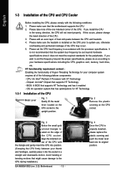
... make sure that supports HT Technology - Fig. 4 Once the CPU is installed on the CPU socket to the CPU during installation.) GA-965GM-DS2 (rev. 2.0) Motherboard - 12 - HT functionality requirement content : Enabling the functionality of Hyper-Threading Technology for HT Technology 1-3-1 Installation ...be set the frequency beyond hardware specifications since it into the socket in accordance with the following platform components: - BIOS: A BIOS that has optimizations for your thumb and forefinger, carefully place it does not meet the required standards for the ...
... make sure that supports HT Technology - Fig. 4 Once the CPU is installed on the CPU socket to the CPU during installation.) GA-965GM-DS2 (rev. 2.0) Motherboard - 12 - HT functionality requirement content : Enabling the functionality of Hyper-Threading Technology for HT Technology 1-3-1 Installation ...be set the frequency beyond hardware specifications since it into the socket in accordance with the following platform components: - BIOS: A BIOS that has optimizations for your thumb and forefinger, carefully place it does not meet the required standards for the ...
Manual
Page 14
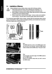
A memory module can differ with the following conditions: 1. The motherboard supports DDRII memory modules, whereby BIOS will automatically detect memory capacity and specifications. Insert the DIMM memory module vertically into the DIMM socket. The memory capacity used is supported by the ... have a foolproof insertion design. Fig.2 Close the plastic clip at both edges of similar capacity, specifications and brand be inserted only in only one direction. GA-965GM-DS2 (rev. 2.0) Motherboard - 14 -
A memory module can differ with the following conditions: 1. The motherboard supports DDRII memory modules, whereby BIOS will automatically detect memory capacity and specifications. Insert the DIMM memory module vertically into the DIMM socket. The memory capacity used is supported by the ... have a foolproof insertion design. Fig.2 Close the plastic clip at both edges of similar capacity, specifications and brand be inserted only in only one direction. GA-965GM-DS2 (rev. 2.0) Motherboard - 14 -
Manual
Page 16
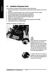
...Read the related expansion card's instruction document before install the expansion card into expansion slot in the slot. 5. Install related driver from the computer. 3. GA-965GM-DS2 (rev. 2.0) Motherboard - 16 - Replace the screw to secure the slot bracket of the PCI Express x16 slot when you try to the onboard ...PCI Express x16 slot and press firmly down on the computer, if necessary, setup BIOS utility of expansion card from BIOS. 8. Be sure the metal contacts on the back of the drawable bar as the picture to release an installed card,...
...Read the related expansion card's instruction document before install the expansion card into expansion slot in the slot. 5. Install related driver from the computer. 3. GA-965GM-DS2 (rev. 2.0) Motherboard - 16 - Replace the screw to secure the slot bracket of the PCI Express x16 slot when you try to the onboard ...PCI Express x16 slot and press firmly down on the computer, if necessary, setup BIOS utility of expansion card from BIOS. 8. Be sure the metal contacts on the back of the drawable bar as the picture to release an installed card,...
Manual
Page 21
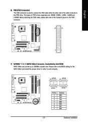
... TXN GND RXN RXP GND - 21 - Before attaching the FDD cable, please take note of the cable connects to work properly. Please refer to the BIOS setting for the SATA 3Gb/s and install the proper driver in the FDD connector. 34 33 2 1 7) SATAII0 / 1 / 2 / 3 (SATA 3Gb/s Connector, Controlled by Intel ICH8) SATA...
... TXN GND RXN RXP GND - 21 - Before attaching the FDD cable, please take note of the cable connects to work properly. Please refer to the BIOS setting for the SATA 3Gb/s and install the proper driver in the FDD connector. 34 33 2 1 7) SATAII0 / 1 / 2 / 3 (SATA 3Gb/s Connector, Controlled by Intel ICH8) SATA...
Manual
Page 22
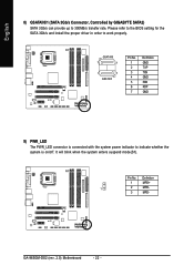
English 8) GSATAII0/1 (SATA 3Gb/s Connector, Controlled by GIGABYTE SATA2) SATA 3Gb/s can provide up to work properly. Please refer to the BIOS setting for the SATA 3Gb/s and install the proper driver in order to 300MB/s transfer rate. Pin No. Definition 1 MPD+ 1 2 MPD- 3 MPD- It will blink ... TXP TXN GND RXN RXP GND 9) PWR_LED The PWR_LED connector is connected with the system power indicator to indicate whether the system is on/off. GA-965GM-DS2 (rev. 2.0) Motherboard - 22 -
English 8) GSATAII0/1 (SATA 3Gb/s Connector, Controlled by GIGABYTE SATA2) SATA 3Gb/s can provide up to work properly. Please refer to the BIOS setting for the SATA 3Gb/s and install the proper driver in order to 300MB/s transfer rate. Pin No. Definition 1 MPD+ 1 2 MPD- 3 MPD- It will blink ... TXP TXN GND RXN RXP GND 9) PWR_LED The PWR_LED connector is connected with the system power indicator to indicate whether the system is on/off. GA-965GM-DS2 (rev. 2.0) Motherboard - 22 -
Manual
Page 27
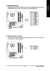
Hardware Installation Definition 1 1 Signal 2 GND - 27 - English 16) COMB (COMB Connector) Be careful with the polarity of the COMB connector. Pin No. You can check the "Case Opened" status in BIOS Setup. Check the pin assignments while you connect the COMB cable. Please contact your nearest dealer for optional COMB cable. 2 10 1 9 Pin No. 1 2 3 4 5 6 7 8 9 10 Definition NDCDBNSINB NSOUTB NDTRBGND NDSRBNRTSBNCTSBNRIBNo Pin 17) CI (Chassis Intrusion, Case Open) This 2-pin connector allows your system to detect if the chassis cover is removed.
Hardware Installation Definition 1 1 Signal 2 GND - 27 - English 16) COMB (COMB Connector) Be careful with the polarity of the COMB connector. Pin No. You can check the "Case Opened" status in BIOS Setup. Check the pin assignments while you connect the COMB cable. Please contact your nearest dealer for optional COMB cable. 2 10 1 9 Pin No. 1 2 3 4 5 6 7 8 9 10 Definition NDCDBNSINB NSOUTB NDTRBGND NDSRBNRTSBNCTSBNRIBNo Pin 17) CI (Chassis Intrusion, Case Open) This 2-pin connector allows your system to detect if the chassis cover is removed.
Manual
Page 29
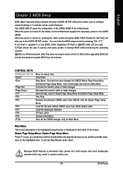
...activate certain system features. Status Page Setup Menu / Option Page Setup Menu Press F1 to DOS before upgrading BIOS but directly download and update BIOS from BIOS default table Load the Optimized Defaults Q-Flash utility System Information Save all the CMOS changes, only for the highlighted... to the CMOS SETUP screen. BIOS Setup The CMOS SETUP saves the configuration in system malfunction. - 29 - When the power is displayed at the bottom of the motherboard. If you to a new BIOS, either Gigabyte's Q-Flash or @BIOS utility can enter the BIOS setup screen by pressing "Ctrl ...
...activate certain system features. Status Page Setup Menu / Option Page Setup Menu Press F1 to DOS before upgrading BIOS but directly download and update BIOS from BIOS default table Load the Optimized Defaults Q-Flash utility System Information Save all the CMOS changes, only for the highlighted... to the CMOS SETUP screen. BIOS Setup The CMOS SETUP saves the configuration in system malfunction. - 29 - When the power is displayed at the bottom of the motherboard. If you to a new BIOS, either Gigabyte's Q-Flash or @BIOS utility can enter the BIOS setup screen by pressing "Ctrl ...
Manual
Page 30
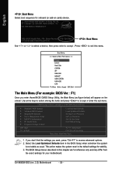
..., then press enter to accept or enter the sub-menu. If you don't find the settings you enter Award BIOS CMOS Setup Utility, the Main Menu (as usual. GA-965GM-DS2 (rev. 2.0) Motherboard - 30 - Use arrow keys to select among the items and press to accept . CMOS... Setup Utility-Copyright (C) 1984-2006 Award Software ` Standard CMOS Features ` Advanced BIOS Features ` Integrated Peripherals ` Power Management Setup ` PnP/PCI ...
..., then press enter to accept or enter the sub-menu. If you don't find the settings you enter Award BIOS CMOS Setup Utility, the Main Menu (as usual. GA-965GM-DS2 (rev. 2.0) Motherboard - 30 - Use arrow keys to select among the items and press to accept . CMOS... Setup Utility-Copyright (C) 1984-2006 Award Software ` Standard CMOS Features ` Advanced BIOS Features ` Integrated Peripherals ` Power Management Setup ` PnP/PCI ...

Manual
Page 31
...132; Load Optimized Defaults Optimized Defaults indicates the value of the system parameters which the system would be in standard compatible BIOS. „ Advanced BIOS Features This setup page includes all the items of Award special enhanced features. „ Integrated Peripherals This setup page ...of Green function features. „ PnP/PCI Configurations This setup page includes all CMOS value changes and exit setup. - 31 - BIOS Setup English „ Standard CMOS Features This setup page includes all the items in best performance configuration. „ Set Supervisor Password Change...
...132; Load Optimized Defaults Optimized Defaults indicates the value of the system parameters which the system would be in standard compatible BIOS. „ Advanced BIOS Features This setup page includes all the items of Award special enhanced features. „ Integrated Peripherals This setup page ...of Green function features. „ PnP/PCI Configurations This setup page includes all CMOS value changes and exit setup. - 31 - BIOS Setup English „ Standard CMOS Features This setup page includes all the items in best performance configuration. „ Set Supervisor Password Change...
Manual
Page 32
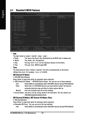
... POST(default) None Select this option for faster system start up. You can use one of the two methods: Auto Allows BIOS to automatically detect IDE/SATA devices during POST(default) GA-965GM-DS2 (rev. 2.0) Motherboard - 32 - Week The week, from 1999 through 2098 Time The times format in the month) Year The year...
... POST(default) None Select this option for faster system start up. You can use one of the two methods: Auto Allows BIOS to automatically detect IDE/SATA devices during POST(default) GA-965GM-DS2 (rev. 2.0) Motherboard - 32 - Week The week, from 1999 through 2098 Time The times format in the month) Year The year...
Manual
Page 33
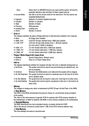
...installed on The category determines whether the computer will stop for the hard drive. This is detected during the POST. BIOS Setup The two options are used . - 33 - Extended Memory The BIOS determines how much extended memory is Enabled). 720K, 3.5" 3.5 inch double-sided drive; 720K byte capacity 1.44M, 3.5"... base (or conventional) memory installed in the system. it will stop for faster system start up . Base Memory The POST of the BIOS will stop for all other errors. (Default value) All, But Diskette The system boot will be stopped. Use this if no IDE/...
...installed on The category determines whether the computer will stop for the hard drive. This is detected during the POST. BIOS Setup The two options are used . - 33 - Extended Memory The BIOS determines how much extended memory is Enabled). 720K, 3.5" 3.5 inch double-sided drive; 720K byte capacity 1.44M, 3.5"... base (or conventional) memory installed in the system. it will stop for faster system start up . Base Memory The POST of the BIOS will stop for all other errors. (Default value) All, But Diskette The system boot will be stopped. Use this if no IDE/...
Manual
Page 34
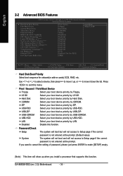
... to Setup page if the correct password is not entered at the prompt. English 2-2 Advanced BIOS Features CMOS Setup Utility-Copyright (C) 1984-2006 Award Software Advanced BIOS Features ` Hard Disk Boot Priority First Boot Device Second Boot Device Third Boot Device Password Check...USB-FDD. Disabled Disable this menu. CDROM Select your boot device priority by CDROM. If you install a processor that supports this function. GA-965GM-DS2 (rev. 2.0) Motherboard - 34 - First / Second / Third Boot Device Floppy Select your boot device priority by Floppy. LS120 Select your...
... to Setup page if the correct password is not entered at the prompt. English 2-2 Advanced BIOS Features CMOS Setup Utility-Copyright (C) 1984-2006 Award Software Advanced BIOS Features ` Hard Disk Boot Priority First Boot Device Second Boot Device Third Boot Device Password Check...USB-FDD. Disabled Disable this menu. CDROM Select your boot device priority by CDROM. If you install a processor that supports this function. GA-965GM-DS2 (rev. 2.0) Motherboard - 34 - First / Second / Third Boot Device Floppy Select your boot device priority by Floppy. LS120 Select your...
Manual
Page 35
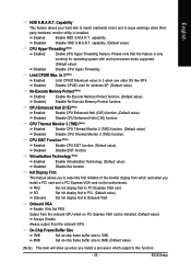
... This feature allows you install a PCI card and a PCI Express VGA card on -chip frame buffer size to 1MB. 8MB Set on the motherboard. capability. BIOS Setup
... This feature allows you install a PCI card and a PCI Express VGA card on -chip frame buffer size to 1MB. 8MB Set on the motherboard. capability. BIOS Setup
Manual
Page 36
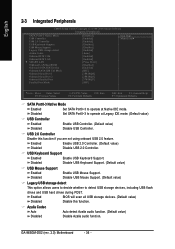
USB Keyboard Support Enabled Enable USB Keyboard Support. Enabled BIOS will scan all USB storage devices. (Default value) Disabled Disable this function if you are not using onboard USB 2.0 feature. GA-965GM-DS2 (rev. 2.0) Motherboard - 36 - USB 2.0 Controller Disable this function. Disabled Disable USB Keyboard Support. (Default value) USB Mouse Support Enabled Disabled Enable USB...
USB Keyboard Support Enabled Enable USB Keyboard Support. Enabled BIOS will scan all USB storage devices. (Default value) Disabled Disable this function if you are not using onboard USB 2.0 feature. GA-965GM-DS2 (rev. 2.0) Motherboard - 36 - USB 2.0 Controller Disable this function. Disabled Disable USB Keyboard Support. (Default value) USB Mouse Support Enabled Disabled Enable USB...
Manual
Page 37
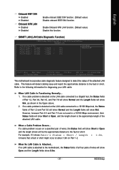
... diagnosing your LAN cable: When LAN Cable Is Functioning Normally... 1. Refer to detect the status of wires will show Open and the Length fields show N/A. BIOS Setup This feature will be the approximate distance to the fault or short. If a cable problem occurs on the LAN cable connected to a 10/100...
... diagnosing your LAN cable: When LAN Cable Is Functioning Normally... 1. Refer to detect the status of wires will show Open and the Length fields show N/A. BIOS Setup This feature will be the approximate distance to the fault or short. If a cable problem occurs on the LAN cable connected to a 10/100...


