Manual
Page 1
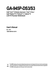
GA-945P-DS3/S3 Intel® CoreTM 2 Extreme dual-core / CoreTM 2 Duo / Intel® Pentium® D / Pentium® 4 / Celeron® D LGA775 Processor Motherboard User's Manual Rev. 3301 12ME-945PDS3-3301R * The WEEE marking on the product indicates this product must not be disposed of with user's other household waste and must be handed over to a designated collection point for the recycling of waste electrical and electronic equipment!! * The WEEE marking applies only in European Union's member states.
GA-945P-DS3/S3 Intel® CoreTM 2 Extreme dual-core / CoreTM 2 Duo / Intel® Pentium® D / Pentium® 4 / Celeron® D LGA775 Processor Motherboard User's Manual Rev. 3301 12ME-945PDS3-3301R * The WEEE marking on the product indicates this product must not be disposed of with user's other household waste and must be handed over to a designated collection point for the recycling of waste electrical and electronic equipment!! * The WEEE marking applies only in European Union's member states.
Manual
Page 2
Motherboard GA-945P-DS3/GA-945P-S3 Oct. 27, 2006 Motherboard GA-945P-DS3/ GA-945P-S3 Oct. 27, 2006
Motherboard GA-945P-DS3/GA-945P-S3 Oct. 27, 2006 Motherboard GA-945P-DS3/ GA-945P-S3 Oct. 27, 2006
Manual
Page 4
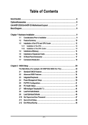
... Status 42 2-7 MB Intelligent Tweaker(M.I /O Back Panel Introduction 17 1-7 Connectors Introduction 18 Chapter 2 BIOS Setup 29 The Main Menu (For example: GA-945P-DS3 BIOS Ver. Table of Contents ItemChecklist ...6 OptionalAccessories ...6 GA-945P-DS3/GA-945P-S3 Motherboard Layout 7 Block Diagram ...8 Chapter 1 Hardware Installation 9 1-1 Considerations Prior to Installation 9 1-2 Feature Summary 10 1-3 Installation of the CPU and CPU Cooler 12...
... Status 42 2-7 MB Intelligent Tweaker(M.I /O Back Panel Introduction 17 1-7 Connectors Introduction 18 Chapter 2 BIOS Setup 29 The Main Menu (For example: GA-945P-DS3 BIOS Ver. Table of Contents ItemChecklist ...6 OptionalAccessories ...6 GA-945P-DS3/GA-945P-S3 Motherboard Layout 7 Block Diagram ...8 Chapter 1 Hardware Installation 9 1-1 Considerations Prior to Installation 9 1-2 Feature Summary 10 1-3 Installation of the CPU and CPU Cooler 12...
Manual
Page 7
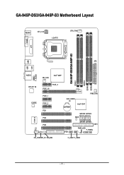
GA-945P-DS3/GA-945P-S3 Motherboard Layout KB_MS ATX_12V LGA775 CPU_FAN COMA LPT GA-945P-DS3/GA-945P-S3 DDRII1 DDRII2 DDRII3 DDRII4 USB USB LAN ATX F_AUDIO AUDIO NB_FAN Intel® 945P RTL8111B CODEC CI IT8718 PCIE_16 PCIE_3 PCIE_1 PCIE_2 PCI1 PCI2 PCI3 CD_IN SPDIF_IO SYS_FAN CLR_CMOS BATTERY Intel® ICH7 PWR_FAN SATAII0 SATAII2 BIOS SATAII1 SATAII3 IDE1 PWR_LED F_PANEL FDD F_USB1 F_USB2 - 7 -
GA-945P-DS3/GA-945P-S3 Motherboard Layout KB_MS ATX_12V LGA775 CPU_FAN COMA LPT GA-945P-DS3/GA-945P-S3 DDRII1 DDRII2 DDRII3 DDRII4 USB USB LAN ATX F_AUDIO AUDIO NB_FAN Intel® 945P RTL8111B CODEC CI IT8718 PCIE_16 PCIE_3 PCIE_1 PCIE_2 PCI1 PCI2 PCI3 CD_IN SPDIF_IO SYS_FAN CLR_CMOS BATTERY Intel® ICH7 PWR_FAN SATAII0 SATAII2 BIOS SATAII1 SATAII3 IDE1 PWR_LED F_PANEL FDD F_USB1 F_USB2 - 7 -
Manual
Page 8
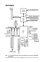
...) LGA775 Processor CPU CLK+/-(266/200/133 MHz) PCI Express x16 LAN RJ45 RTL8111B Host Interface DDRII 667(Note)/533/400 MHz DIMM Intel® 945P Dual Channel Memory MCH CLK (266/200/133 MHz) PCI Express Bus x1 x1 x1 x1 PCIe CLK Intel® (100 MHz) ICH7 3 PCI Express... MIC Line-Out Line-In SPDIF In SPDIF Out 3 PCI PCI CLK (33 MHz) 8 USB Ports (Note) To use a DDRII 667 memory module on the motherboard, you must install a 1066/800 MHz FSB processor. - 8 -
...) LGA775 Processor CPU CLK+/-(266/200/133 MHz) PCI Express x16 LAN RJ45 RTL8111B Host Interface DDRII 667(Note)/533/400 MHz DIMM Intel® 945P Dual Channel Memory MCH CLK (266/200/133 MHz) PCI Express Bus x1 x1 x1 x1 PCIe CLK Intel® (100 MHz) ICH7 3 PCI Express... MIC Line-Out Line-In SPDIF In SPDIF Out 3 PCI PCI CLK (33 MHz) 8 USB Ports (Note) To use a DDRII 667 memory module on the motherboard, you must install a 1066/800 MHz FSB processor. - 8 -
Manual
Page 9
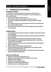
... all cables and power connectors are no leftover screws or metal components placed on the motherboard or within a electrostatic shielding container. 5. Before using the product, please verify that the power supply is best to be an unofficial Gigabyte product. - 9 - Instances of uncertified components. 5. Damage due to installation, please follow the instructions below...
... all cables and power connectors are no leftover screws or metal components placed on the motherboard or within a electrostatic shielding container. 5. Before using the product, please verify that the power supply is best to be an unofficial Gigabyte product. - 9 - Instances of uncertified components. 5. Damage due to installation, please follow the instructions below...
Manual
Page 10
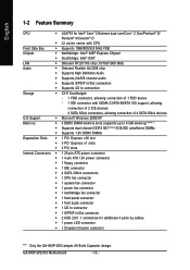
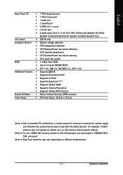
GA-945P-DS3/S3 Motherboard - 10 - English 1-2 Feature Summary CPU Š LGA775 for Intel® CoreTM 2 Extreme dual-core/CoreTM 2 Duo/Pentium® D/ Pentium® 4/Celeron® D Š L2 cache varies with CPU Front Side Bus Š Supports 1066/800/533 MHz FSB Chipset Š Northbridge: Intel® 945P Express Chipset Š Southbridge: Intel&#...Š 1 S/PDIF In/Out connector Š 2 USB 2.0/1.1 connectors for additional 4 ports by cables Š 1 power LED connector Š 1 Chassis Intrusion connector "*" Only the GA-945P-DS3 adopts All-Solid Capacitor design.
GA-945P-DS3/S3 Motherboard - 10 - English 1-2 Feature Summary CPU Š LGA775 for Intel® CoreTM 2 Extreme dual-core/CoreTM 2 Duo/Pentium® D/ Pentium® 4/Celeron® D Š L2 cache varies with CPU Front Side Bus Š Supports 1066/800/533 MHz FSB Chipset Š Northbridge: Intel® 945P Express Chipset Š Southbridge: Intel&#...Š 1 S/PDIF In/Out connector Š 2 USB 2.0/1.1 connectors for additional 4 ports by cables Š 1 power LED connector Š 1 Chassis Intrusion connector "*" Only the GA-945P-DS3 adopts All-Solid Capacitor design.
Manual
Page 11
..., a certain amount of memory size will instead be shown as 3.xx GB memory during system startup. (Note 2) To use a DDRII 667 memory module on the motherboard, you must install a 1066/800 MHz FSB processor. (Note 3) EasyTune functions may vary depending on different...
..., a certain amount of memory size will instead be shown as 3.xx GB memory during system startup. (Note 2) To use a DDRII 667 memory module on the motherboard, you must install a 1066/800 MHz FSB processor. (Note 3) EasyTune functions may vary depending on different...
Manual
Page 12
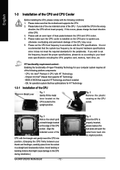
...back into its original position. Fig. 3 Notice the small gold colored triangle located on the CPU prior to the CPU during installation.) GA-945P-DS3/S3 Motherboard - 12 - Align the indented corner of the CPU with the triangle and gently insert the CPU into the socket in a straight ...CPU in accordance with the CPU specifications. CPU: An Intel® Pentium 4 CPU with HT Technology - Avoid twisting or bending motions that the motherboard supports the CPU. 2. Fig. 2 Remove the plastic covering on the CPU socket to your computer system requires all of the following conditions: ...
...back into its original position. Fig. 3 Notice the small gold colored triangle located on the CPU prior to the CPU during installation.) GA-945P-DS3/S3 Motherboard - 12 - Align the indented corner of the CPU with the triangle and gently insert the CPU into the socket in a straight ...CPU in accordance with the CPU specifications. CPU: An Intel® Pentium 4 CPU with HT Technology - Avoid twisting or bending motions that the motherboard supports the CPU. 2. Fig. 2 Remove the plastic covering on the CPU socket to your computer system requires all of the following conditions: ...
Manual
Page 13
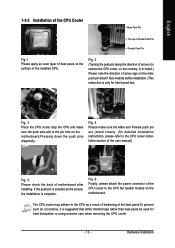
... connector of the CPU cooler to install.) Please note the direction of arrow sign on the motherboard.Pressing down the push pins diagonally. Hardware Installation Fig. 4 Please make sure the push pins...aim to the CPU cooler installation section of the user manual) Fig. 5 Please check the back of motherboard after installing. The CPU cooler may adhere to the CPU as the picture, the installation is only for ...of Female Push Pin Female Push Pin Fig.1 Please apply an even layer of heat paste on the motherboard. If the push pin is inserted as a result of hardening of the installed CPU. Fig. ...
... connector of the CPU cooler to install.) Please note the direction of arrow sign on the motherboard.Pressing down the push pins diagonally. Hardware Installation Fig. 4 Please make sure the push pins...aim to the CPU cooler installation section of the user manual) Fig. 5 Please check the back of motherboard after installing. The CPU cooler may adhere to the CPU as the picture, the installation is only for ...of Female Push Pin Female Push Pin Fig.1 Please apply an even layer of heat paste on the motherboard. If the push pin is inserted as a result of hardening of the installed CPU. Fig. ...
Manual
Page 14
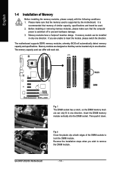
It is recommended that the computer power is supported by the motherboard. Before installing or removing memory modules, please make sure that they can differ with the following conditions: 1. Memory modules have a foolproof insertion design...whereby BIOS will automatically detect memory capacity and specifications. The memory capacity used is switched off to insert the module, please switch the direction. GA-945P-DS3/S3 Motherboard - 14 - Please make sure that memory of similar capacity, specifications and brand be installed in one direction. Insert the DIMM memory module ...
It is recommended that the computer power is supported by the motherboard. Before installing or removing memory modules, please make sure that they can differ with the following conditions: 1. Memory modules have a foolproof insertion design...whereby BIOS will automatically detect memory capacity and specifications. The memory capacity used is switched off to insert the module, please switch the direction. GA-945P-DS3/S3 Motherboard - 14 - Please make sure that memory of similar capacity, specifications and brand be installed in one direction. Insert the DIMM memory module ...
Manual
Page 16
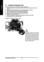
... necessary, setup BIOS utility of expansion card from BIOS. 8. Install related driver from the computer. 3. Power on the card are indeed seated in motherboard. 4. Read the related expansion card's instruction document before install the expansion card into expansion slot in the slot. 5. Installing a PCI Express x16 ... the latch as the picture to the left shows to the onboard PCI Express x16 slot and press firmly down on the slot. GA-945P-DS3/S3 Motherboard - 16 - English 1-5 Installation of Expansion Cards You can install your expansion card by the latch at the end of the PCI...
... necessary, setup BIOS utility of expansion card from BIOS. 8. Install related driver from the computer. 3. Power on the card are indeed seated in motherboard. 4. Read the related expansion card's instruction document before install the expansion card into expansion slot in the slot. 5. Installing a PCI Express x16 ... the latch as the picture to the left shows to the onboard PCI Express x16 slot and press firmly down on the slot. GA-945P-DS3/S3 Motherboard - 16 - English 1-5 Installation of Expansion Cards You can install your expansion card by the latch at the end of the PCI...
Manual
Page 18
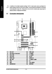
... 7) FDD 8) IDE1 9) SATAII0/1/2/3 7 15 10 11 10) PWR_LED 11) F_PANEL 12) F_AUDIO 13) CD_IN 14) SPDIF_IO 15) F_USB1/F_USB2 16) CI 17) CLR_CMOS 18) BATTERY GA-945P-DS3/S3 Motherboard - 18 - Please refer to the 2-/4-/6-/8-
... 7) FDD 8) IDE1 9) SATAII0/1/2/3 7 15 10 11 10) PWR_LED 11) F_PANEL 12) F_AUDIO 13) CD_IN 14) SPDIF_IO 15) F_USB1/F_USB2 16) CI 17) CLR_CMOS 18) BATTERY GA-945P-DS3/S3 Motherboard - 18 - Please refer to the 2-/4-/6-/8-
Manual
Page 19
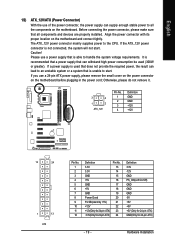
... stable power to all components and devices are properly installed. Before connecting the power connector, please make sure that all the components on the motherboard. English 1/2) ATX_12V/ATX (Power Connector) With the use a power supply that is able to handle the system voltage requirements. The ATX_12V ...supplies power to start . Caution! If a power supply is used (300W or greater). Align the power connector with its proper location on the motherboard before plugging in the power cord; It is not connected, the system will not start . If you use a 24-pin ATX power supply,...
... stable power to all components and devices are properly installed. Before connecting the power connector, please make sure that all the components on the motherboard. English 1/2) ATX_12V/ATX (Power Connector) With the use a power supply that is able to handle the system voltage requirements. The ATX_12V ...supplies power to start . Caution! If a power supply is used (300W or greater). Align the power connector with its proper location on the motherboard before plugging in the power cord; It is not connected, the system will not start . If you use a 24-pin ATX power supply,...
Manual
Page 20
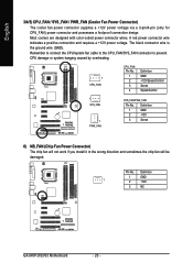
... overheating. 1 CPU_FAN CPU_FAN: Pin No. 1 2 3 4 Definition GND +12V/Speed Control Sense Speed Control 1 SYS_FAN 1 PWR_FAN SYS_FAN/PWR_FAN: Pin No. Pin No. Definition 1 GND 1 2 +12V 3 NC GA-945P-DS3/S3 Motherboard - 20 -
... overheating. 1 CPU_FAN CPU_FAN: Pin No. 1 2 3 4 Definition GND +12V/Speed Control Sense Speed Control 1 SYS_FAN 1 PWR_FAN SYS_FAN/PWR_FAN: Pin No. Pin No. Definition 1 GND 1 2 +12V 3 NC GA-945P-DS3/S3 Motherboard - 20 -
Manual
Page 22
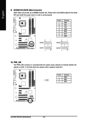
... GND 7 1 SATAII2 SATAII1 1 7 SATAII3 1 7 10) PWR_LED The PWR_LED connector is on/off. It will blink when the system enters suspend mode (S1). Pin No. GA-945P-DS3/S3 Motherboard - 22 - English 9) SATAII0/1/2/3 (SATA 3Gb/s Connector) SATA 3Gb/s can provide up to indicate whether the system is connected with the system power indicator to 300MB...
... GND 7 1 SATAII2 SATAII1 1 7 SATAII3 1 7 10) PWR_LED The PWR_LED connector is on/off. It will blink when the system enters suspend mode (S1). Pin No. GA-945P-DS3/S3 Motherboard - 22 - English 9) SATAII0/1/2/3 (SATA 3Gb/s Connector) SATA 3Gb/s can provide up to indicate whether the system is connected with the system power indicator to 300MB...
Manual
Page 24
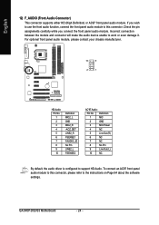
... manufacturer. 10 9 2 1 HD Audio: Pin No. 1 2 3 4 5 6 7 8 9 10 Definition MIC2_L GND MIC2_R -ACZ_DET LINE2_R FSENSE1 FAUDIO_JD No Pin LINE2_L FSENSE2 AC'97 Audio: Pin No. GA-945P-DS3/S3 Motherboard - 24 - To connect an AC97 front panel audio module to the instructions on Page 64 about the software settings. English 12) F_AUDIO (Front Audio Connector...
... manufacturer. 10 9 2 1 HD Audio: Pin No. 1 2 3 4 5 6 7 8 9 10 Definition MIC2_L GND MIC2_R -ACZ_DET LINE2_R FSENSE1 FAUDIO_JD No Pin LINE2_L FSENSE2 AC'97 Audio: Pin No. GA-945P-DS3/S3 Motherboard - 24 - To connect an AC97 front panel audio module to the instructions on Page 64 about the software settings. English 12) F_AUDIO (Front Audio Connector...
Manual
Page 26
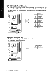
... USB cable, incorrect connection between the cable and connector will make the device unable to detect if the chassis cover is removed. Definition 1 Signal 1 2 GND GA-945P-DS3/S3 Motherboard - 26 -
... USB cable, incorrect connection between the cable and connector will make the device unable to detect if the chassis cover is removed. Definition 1 Signal 1 2 GND GA-945P-DS3/S3 Motherboard - 26 -

Manual
Page 28
English GA-945P-DS3/S3 Motherboard - 28 -
English GA-945P-DS3/S3 Motherboard - 28 -
Manual
Page 29
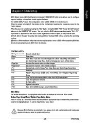
...caution and avoid inadequate operation that describes the appropriate keys to use and the possible selections for Main Menu Main Menu The on the motherboard supplies the necessary power to the CMOS SETUP screen. BIOS Setup To exit the Help Window press . When the power is displayed... You can be used. If you to the CMOS SRAM. Status Page Setup Menu / Option Page Setup Menu Press F1 to a new BIOS, either Gigabyte's Q-Flash or @BIOS utility can enter the BIOS setup screen by pressing "Ctrl + F1". CONTROL KEYS Enter> Move to activate certain system features. Exit...
...caution and avoid inadequate operation that describes the appropriate keys to use and the possible selections for Main Menu Main Menu The on the motherboard supplies the necessary power to the CMOS SETUP screen. BIOS Setup To exit the Help Window press . When the power is displayed... You can be used. If you to the CMOS SRAM. Status Page Setup Menu / Option Page Setup Menu Press F1 to a new BIOS, either Gigabyte's Q-Flash or @BIOS utility can enter the BIOS setup screen by pressing "Ctrl + F1". CONTROL KEYS Enter> Move to activate certain system features. Exit...


