Manual
Page 10
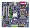
... CPU Chipset Memory Slots IDE Connections Onboard SATA FDD Connections Peripherals Onboard VGA Onboard LAN Onboard Audio I/O Control Hardware Monitor Š Supports the latest Intel® Pentium® 4 LGA775 CPU Š Supports 800/533MHz FSB Š L2 cache varies with processors Š Northbridge:SiS® 661FX Š Southbridge: SiS® 964 Š 2 184-pin DDR DIMM slots Š Supports DDR400/333/266 DIMM Š Supports up to 2GB (Max.) Š 1 AGP slot 4X/8X (1.5V) device support Š 3 PCI slots Š 2 IDE connection...
... CPU Chipset Memory Slots IDE Connections Onboard SATA FDD Connections Peripherals Onboard VGA Onboard LAN Onboard Audio I/O Control Hardware Monitor Š Supports the latest Intel® Pentium® 4 LGA775 CPU Š Supports 800/533MHz FSB Š L2 cache varies with processors Š Northbridge:SiS® 661FX Š Southbridge: SiS® 964 Š 2 184-pin DDR DIMM slots Š Supports DDR400/333/266 DIMM Š Supports up to 2GB (Max.) Š 1 AGP slot 4X/8X (1.5V) device support Š 3 PCI slots Š 2 IDE connection...
Manual
Page 20
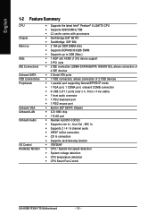
... 2 1 GA-8S661FXM-775 Motherboard - 20 - If you wish to connect two IDE devices, please set the jumper on one IDE cable, and the single IDE cable can then connect to the FDD drive. One IDE connector can connect to one IDE device as Master and the other as Slave (for information on settings, please refer to the instructions located on the IDE device). 40 39 40 39 2 12 1 IDE2 Connector IDE1 Connector 6) FDD (FDD Connector) The FDD connector is used...
... 2 1 GA-8S661FXM-775 Motherboard - 20 - If you wish to connect two IDE devices, please set the jumper on one IDE cable, and the single IDE cable can then connect to the FDD drive. One IDE connector can connect to one IDE device as Master and the other as Slave (for information on settings, please refer to the instructions located on the IDE device). 40 39 40 39 2 12 1 IDE2 Connector IDE1 Connector 6) FDD (FDD Connector) The FDD connector is used...
Manual
Page 22
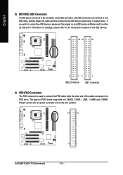
...Close: Power On/Off Pin 1: LED anode(+) Pin 2: LED cathode(-) NC - 22 - RESRES+ NC HD (IDE Hard Disk Active LED) SPEAK (Speaker Connector) RES (Reset Switch) PW (Power Switch) MSG (Message LED/Power/Sleep LED) NC GA-8S661FXM-775 Motherboard Reset Switch IDE Hard Disk Active LED Pin 1: LED anode(+) Pin 2: LED cathode(-) Pin 1: VCC(+) Pin 2- of your nearest dealer for optional SUR_CEN cable. 26 15 Pin No. 1 2 3 4 5 6 Definition SUR OUTL SUR OUTR GND No Pin CENTER_OUT BASS_OUT 10) F_PANEL (Front Panel Connector) Please connect the power LED, PC speaker, reset switch and power switch etc...
...Close: Power On/Off Pin 1: LED anode(+) Pin 2: LED cathode(-) NC - 22 - RESRES+ NC HD (IDE Hard Disk Active LED) SPEAK (Speaker Connector) RES (Reset Switch) PW (Power Switch) MSG (Message LED/Power/Sleep LED) NC GA-8S661FXM-775 Motherboard Reset Switch IDE Hard Disk Active LED Pin 1: LED anode(+) Pin 2: LED cathode(-) Pin 1: VCC(+) Pin 2- of your nearest dealer for optional SUR_CEN cable. 26 15 Pin No. 1 2 3 4 5 6 Definition SUR OUTL SUR OUTR GND No Pin CENTER_OUT BASS_OUT 10) F_PANEL (Front Panel Connector) Please connect the power LED, PC speaker, reset switch and power switch etc...
Manual
Page 32
... the hard drive. For example, 1 p.m. IDE Channel 0/Channel 1 Master(Slave) setup You can manually input the correct settings Access Mode Use this if no IDE devices are : CHS/LBA/Large/Auto (Default:Auto) Capacity Capacity of sectors GA-8S661FXM-775 Motherboard - 32 - to Dec. Jan. Halt On Base Memory Extended Memory Total Memory [All, But Keyboard] 640K 127M 128M 1 to 2098 KLJI: Move Enter: Select F5: Previous Values +/-/PU/PD: Value F10: Save F6: Fail-Safe Defaults...
... the hard drive. For example, 1 p.m. IDE Channel 0/Channel 1 Master(Slave) setup You can manually input the correct settings Access Mode Use this if no IDE devices are : CHS/LBA/Large/Auto (Default:Auto) Capacity Capacity of sectors GA-8S661FXM-775 Motherboard - 32 - to Dec. Jan. Halt On Base Memory Extended Memory Total Memory [All, But Keyboard] 640K 127M 128M 1 to 2098 KLJI: Move Enter: Select F5: Previous Values +/-/PU/PD: Value F10: Save F6: Fail-Safe Defaults...
Manual
Page 35
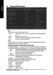
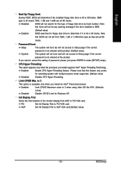
... option is not entered at the prompt. If you install supports Intel® Hyper-Threading Technology. Disabled BIOS will not search for operating system with multiprocessors mode supported. (Default value) Disabled Disable CPU Hyper-Threading. English Boot Up Floppy Seek During POST, BIOS will determine if the installed floppy disk drive is 40 or 80 tracks. 360K type is 40 or 80 tracks. Enabled Enable CPU Hyper-Threading feature. AGP Set Init Display First to 3 when using older...
... option is not entered at the prompt. If you install supports Intel® Hyper-Threading Technology. Disabled BIOS will not search for operating system with multiprocessors mode supported. (Default value) Disabled Disable CPU Hyper-Threading. English Boot Up Floppy Seek During POST, BIOS will determine if the installed floppy disk drive is 40 or 80 tracks. 360K type is 40 or 80 tracks. Enabled Enable CPU Hyper-Threading feature. AGP Set Init Display First to 3 when using older...
Manual
Page 42
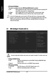
...wire fans PWM control specifications. Auto BIOS will automatically set DRAM Timing manually. GA-8S661FXM-775 Motherboard - 42 - Auto BIOS autodetects the type of CPU fan you installed and sets the optimal CPU Smart FAN control mode for CPU fans with a 3-pin fan power cable. PWM Set to PWM when you use a CPU fan with a 4-pin fan power cable. In fact, the Voltage option can 't boot. Configure DRAM Timing Auto BIOS will automatically detect CAS Latency. CAS Latency Setting 2T/2.5T/3T Set CAS Latency to Voltage when you use a CPU fan with 3-pin or 4-pin...
...wire fans PWM control specifications. Auto BIOS will automatically set DRAM Timing manually. GA-8S661FXM-775 Motherboard - 42 - Auto BIOS autodetects the type of CPU fan you installed and sets the optimal CPU Smart FAN control mode for CPU fans with a 3-pin fan power cable. PWM Set to PWM when you use a CPU fan with a 4-pin fan power cable. In fact, the Voltage option can 't boot. Configure DRAM Timing Auto BIOS will automatically detect CAS Latency. CAS Latency Setting 2T/2.5T/3T Set CAS Latency to Voltage when you use a CPU fan with 3-pin or 4-pin...
Manual
Page 53
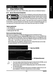
... of the hard disk will appear in your CD-ROM drive. VESA-supported VGA cards How to Xpress Recovery2 can be immediately installed once you can simply press F9 during system power-on PATA and SATA IDE controllers. Save the settings and exit the BIOS Setup. After the steps above are completed, subsequent access to use the Xpress Recovery2 Initial access by booting from CD-ROM. Boot from CD/DVD: Award Modular BIOS v6...
... of the hard disk will appear in your CD-ROM drive. VESA-supported VGA cards How to Xpress Recovery2 can be immediately installed once you can simply press F9 during system power-on PATA and SATA IDE controllers. Save the settings and exit the BIOS Setup. After the steps above are completed, subsequent access to use the Xpress Recovery2 Initial access by booting from CD-ROM. Boot from CD/DVD: Award Modular BIOS v6...
Manual
Page 56
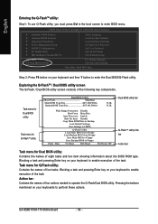
...: To use Q-Flash utility, you must press Del in the boot screen to enter BIOS menu. CMOS Setup Utility-Copyright (C) 1984-2004 Award Software Standard CMOS Features Advanced BIOS Features Integrated Peripherals Power Management Setup PnP/PCI Configurations PC Health Status MB Intelligent Tweaker(M.I.T.) Select Language Load Fail-Safe Defaults Load Optimized Defaults Set Supervisor Password Set User Password Save & Exit Setup Exit Without Saving ESC: Quit F8: Dual BIOS/Q-Flash F3: Change Language F10: Save & Exit Setup Time, Date, Hard Disk Type... Exploring the Q-FlashTM / Dual BIOS...
...: To use Q-Flash utility, you must press Del in the boot screen to enter BIOS menu. CMOS Setup Utility-Copyright (C) 1984-2004 Award Software Standard CMOS Features Advanced BIOS Features Integrated Peripherals Power Management Setup PnP/PCI Configurations PC Health Status MB Intelligent Tweaker(M.I.T.) Select Language Load Fail-Safe Defaults Load Optimized Defaults Set Supervisor Password Set User Password Save & Exit Setup Exit Without Saving ESC: Quit F8: Dual BIOS/Q-Flash F3: Change Language F10: Save & Exit Setup Time, Date, Hard Disk Type... Exploring the Q-FlashTM / Dual BIOS...

Manual
Page 58
... enter SETUP / Dual BIOS / Q-Flash / F9 For Xpress Recovery 09/23/2003-i875P-6A79BG03C-00 GA-8S661FXM-775 Motherboard - 58 - Award Modular BIOS v6.00PG, An Energy Star Ally Copyright (C) 1984-2003, Award Software, Inc. Press any keys to return to exit the Q-Flash utility. Halt On Error Disable CPopleyasMe apirneRssOaMnyDkaetya tto cBoanctkiunpue Load Default Settings Save Settings to CMOS Q-Flash Utility Load Main BIOS from Floppy Load Backup BIOS from Floppy Save Main BIOS to Floppy Save Backup BIOS to flash the backup BIOS, too. 5. Dual BIOS Utility Boot From Main Bios...
... enter SETUP / Dual BIOS / Q-Flash / F9 For Xpress Recovery 09/23/2003-i875P-6A79BG03C-00 GA-8S661FXM-775 Motherboard - 58 - Award Modular BIOS v6.00PG, An Energy Star Ally Copyright (C) 1984-2003, Award Software, Inc. Press any keys to return to exit the Q-Flash utility. Halt On Error Disable CPopleyasMe apirneRssOaMnyDkaetya tto cBoanctkiunpue Load Default Settings Save Settings to CMOS Q-Flash Utility Load Main BIOS from Floppy Load Backup BIOS from Floppy Save Main BIOS to Floppy Save Backup BIOS to flash the backup BIOS, too. 5. Dual BIOS Utility Boot From Main Bios...
Manual
Page 70
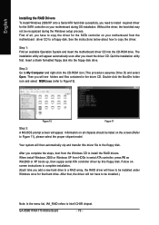
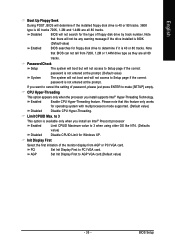
... menu list, IAA_RAID refers to Figure 11), please select the proper chipset model. Without the driver, the hard disk may not be listed on your motherboard during the Windows setup process. Step 1: Find an available Operation System and insert the motherboard driver CD into the floppy disk drive. GA-8S661FXM-775 Motherboard - 70 - First of all chipsets should be recognized during OS installation. Then you need to install required driver for the SATA controller on the screen...
... menu list, IAA_RAID refers to Figure 11), please select the proper chipset model. Without the driver, the hard disk may not be listed on your motherboard during the Windows setup process. Step 1: Find an available Operation System and insert the motherboard driver CD into the floppy disk drive. GA-8S661FXM-775 Motherboard - 70 - First of all chipsets should be recognized during OS installation. Then you need to install required driver for the SATA controller on the screen...

Manual
Page 71
... 2: After installing the audio driver, you use speakers with amplifier to enable the function! 2 Channel Audio Setup We recommend that you 'll find a Sound Effect icon on the lower right hand taskbar. Appendix English 4-1-4 2 / 4 / 6 Channel Audio Function Introduction The following setup is applied. STEP 3: On the AC97 Audio Configuration menu, click the Speaker Configuration tab and select the 2-channel mode for Windows 98SE/2000/ME/XP. STEP 1: Connect the stereo speakers or earphone...
... 2: After installing the audio driver, you use speakers with amplifier to enable the function! 2 Channel Audio Setup We recommend that you 'll find a Sound Effect icon on the lower right hand taskbar. Appendix English 4-1-4 2 / 4 / 6 Channel Audio Function Introduction The following setup is applied. STEP 3: On the AC97 Audio Configuration menu, click the Speaker Configuration tab and select the 2-channel mode for Windows 98SE/2000/ME/XP. STEP 1: Connect the stereo speakers or earphone...
Manual
Page 79
... and F1 keys after updating BIOS. gate A20 failure 7 beeps Processor exception interrupt error 8 beeps Display memory read/write failure 9 beeps ROM checksum error 10 beeps CMOS shutdown register read/write error 11 beeps Cache memory bad AWARD BIOS Beep Codes 1 short: System boots successfully 2 short: CMOS setting error 1 long 1 short: DRAM or M/B error 1 long 2 short: Monitor or display card error 1 long 3 short: Keyboard error 1 long 9 short: BIOS ROM error Continuous long beeps: DRAM error Continuous short beeps: Power error - 79 - Re-insert the battery to the Clear CMOS steps in...
... and F1 keys after updating BIOS. gate A20 failure 7 beeps Processor exception interrupt error 8 beeps Display memory read/write failure 9 beeps ROM checksum error 10 beeps CMOS shutdown register read/write error 11 beeps Cache memory bad AWARD BIOS Beep Codes 1 short: System boots successfully 2 short: CMOS setting error 1 long 1 short: DRAM or M/B error 1 long 2 short: Monitor or display card error 1 long 3 short: Keyboard error 1 long 9 short: BIOS ROM error Continuous long beeps: DRAM error Continuous short beeps: Power error - 79 - Re-insert the battery to the Clear CMOS steps in...
Manual
Page 10
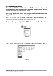
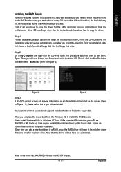
... during the Windows setup process. ¤å First of all, you need to copy the driver for the SATA controller during OS installation. The installation utility will appear automatically. Quit the installation utility first. Step 2: Go to a floppy disk. Ác (4) Making a SATA Driver Disk Åé To install Windows 2000/XP onto a SATA hard drive on the SiS 964 controller successfully, you need to install required driver for the SATA controller from the motherboard driver CD to...
... during the Windows setup process. ¤å First of all, you need to copy the driver for the SATA controller during OS installation. The installation utility will appear automatically. Quit the installation utility first. Step 2: Go to a floppy disk. Ác (4) Making a SATA Driver Disk Åé To install Windows 2000/XP onto a SATA hard drive on the SiS 964 controller successfully, you need to install required driver for the SATA controller from the motherboard driver CD to...
Manual
Page 12
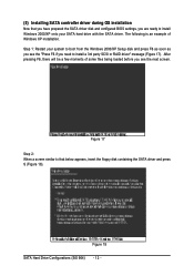
... SATA driver disk and configured BIOS settings, you are ready to install Windows 2000/XP onto your system to boot from the Windows 2000/XP Setup disk and press F6 as soon as you see the "Press F6 if you see the next screen. Figure 18 SATA Hard Drive Configurations (SiS 964) - 12 - Figure 17 Step 2: When a screen similar to install a 3rd party SCSI or RAID driver" message (Figure 17). Ác (5) Installing SATA controller driver...
... SATA driver disk and configured BIOS settings, you are ready to install Windows 2000/XP onto your system to boot from the Windows 2000/XP Setup disk and press F6 as soon as you see the "Press F6 if you see the next screen. Figure 18 SATA Hard Drive Configurations (SiS 964) - 12 - Figure 17 Step 2: When a screen similar to install a 3rd party SCSI or RAID driver" message (Figure 17). Ác (5) Installing SATA controller driver...

Manual
Page 22
... optional SUR_CEN cable. 26 15 Pin No. 1 2 3 4 5 6 Definition SUR OUTL SUR OUTR GND No Pin CENTER_OUT BASS_OUT 10) F_PANEL (Front Panel Connector) Please connect the power LED, PC speaker, reset switch and power switch etc. English 9) SUR_CEN Please contact your chassis front panel to the F_PANEL connector according to the pin assignments below. RESRES+ NC HD (IDE Hard Disk Active LED) SPEAK (Speaker Connector) RES (Reset Switch) PW (Power Switch) MSG (Message LED/Power/Sleep LED) NC GA-8S661FXM-775 Motherboard Reset Switch IDE Hard Disk Active LED Pin 1: LED anode(+) Pin 2: LED...
... optional SUR_CEN cable. 26 15 Pin No. 1 2 3 4 5 6 Definition SUR OUTL SUR OUTR GND No Pin CENTER_OUT BASS_OUT 10) F_PANEL (Front Panel Connector) Please connect the power LED, PC speaker, reset switch and power switch etc. English 9) SUR_CEN Please contact your chassis front panel to the F_PANEL connector according to the pin assignments below. RESRES+ NC HD (IDE Hard Disk Active LED) SPEAK (Speaker Connector) RES (Reset Switch) PW (Power Switch) MSG (Message LED/Power/Sleep LED) NC GA-8S661FXM-775 Motherboard Reset Switch IDE Hard Disk Active LED Pin 1: LED anode(+) Pin 2: LED...
Manual
Page 35
... with multiprocessors mode supported. (Default value) Disabled Disable CPU Hyper-Threading. Enabled Enable CPU Hyper-Threading feature. Init Display First Select the first initiation of floppy disk drive by track number. PCI Set Init Display First to determine if it is 40 or 80 tracks. BIOS Setup to 3 This option is available only when you install supports Intel® Hyper-Threading Technology. English Boot Up Floppy Seek During POST, BIOS will determine if the installed floppy disk drive is 40...
... with multiprocessors mode supported. (Default value) Disabled Disable CPU Hyper-Threading. Enabled Enable CPU Hyper-Threading feature. Init Display First Select the first initiation of floppy disk drive by track number. PCI Set Init Display First to determine if it is 40 or 80 tracks. BIOS Setup to 3 This option is available only when you install supports Intel® Hyper-Threading Technology. English Boot Up Floppy Seek During POST, BIOS will determine if the installed floppy disk drive is 40...

Manual
Page 42
... Defaults Incorrect using these features may make system can be used for it. (Default Value) Voltage Set to PWM when you installed and sets the optimal CPU Smart FAN control mode for CPU fans with a 4-pin fan power cable. With such CPU fans, selecting PWM will automatically detect CAS Latency. For power users only. Clear CMOS to set up the DRAM Timing by manual Warning: Wrong DRAM Timing may cause your system corrupted. GA-8S661FXM-775 Motherboard - 42 - Auto BIOS autodetects the type of CPU fan you use a CPU fan with a 3-pin fan power cable...
... Defaults Incorrect using these features may make system can be used for it. (Default Value) Voltage Set to PWM when you installed and sets the optimal CPU Smart FAN control mode for CPU fans with a 4-pin fan power cable. With such CPU fans, selecting PWM will automatically detect CAS Latency. For power users only. Clear CMOS to set up the DRAM Timing by manual Warning: Wrong DRAM Timing may cause your system corrupted. GA-8S661FXM-775 Motherboard - 42 - Auto BIOS autodetects the type of CPU fan you use a CPU fan with a 3-pin fan power cable...

Manual
Page 57
... Main Bios Main ROM Type/Size SST 49LF004A Backup ROM Type/Size SST 49LF004A 512K 512K Wide Range Protection Disable Boot From Main Bios Auto Recovery Enable Halt On Error Disable Copy Main ROM Data to Backup Load Default Settings Save Settings to CMOS Q-Flash Utility Load Main BIOS from Floppy Load Backup BIOS from Floppy Save Main BIOS to Floppy Save Backup BIOS to enable execution of eight tasks and two item showing information about the BIOS ROM type. Blocking a task and pressing Enter key on your keyboard to Floppy Enter : Run KL:Move ESC:Reset F10:Power...
... Main Bios Main ROM Type/Size SST 49LF004A Backup ROM Type/Size SST 49LF004A 512K 512K Wide Range Protection Disable Boot From Main Bios Auto Recovery Enable Halt On Error Disable Copy Main ROM Data to Backup Load Default Settings Save Settings to CMOS Q-Flash Utility Load Main BIOS from Floppy Load Backup BIOS from Floppy Save Main BIOS to Floppy Save Backup BIOS to enable execution of eight tasks and two item showing information about the BIOS ROM type. Blocking a task and pressing Enter key on your keyboard to Floppy Enter : Run KL:Move ESC:Reset F10:Power...
Manual
Page 71
... Win2000 or XP boots up, then supply serial ATA controller driver by this driver file to copy the driver. Information on your motherboard during the Windows setup process. When install Windows 2000 or Windows XP from the Windows CD to My Computer and right-click the CD-ROM icon (This procedure assumes Drive D) and select Open. See the instructions below about how to the floppy disk. The installation utility will then automatically...
... Win2000 or XP boots up, then supply serial ATA controller driver by this driver file to copy the driver. Information on your motherboard during the Windows setup process. When install Windows 2000 or Windows XP from the Windows CD to My Computer and right-click the CD-ROM icon (This procedure assumes Drive D) and select Open. See the instructions below about how to the floppy disk. The installation utility will then automatically...
Manual
Page 80
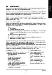
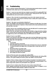
... F1 keys after entering BIOS menu and you are hidden in the manual. Please refer to the Clear CMOS steps in new BIOS version. To check general asked questions. Question 5: How do I connect the boot HDD to a floppy disk before installing drivers. Answer: Please remember to load Fail-Safe Defaults (Or Load BIOS Defaults) after computer shuts down ? English 4-2 Troubleshooting Below is a collection of general asked questions based on a specific motherboard model, please log on after updating BIOS?
... F1 keys after entering BIOS menu and you are hidden in the manual. Please refer to the Clear CMOS steps in new BIOS version. To check general asked questions. Question 5: How do I connect the boot HDD to a floppy disk before installing drivers. Answer: Please remember to load Fail-Safe Defaults (Or Load BIOS Defaults) after computer shuts down ? English 4-2 Troubleshooting Below is a collection of general asked questions based on a specific motherboard model, please log on after updating BIOS?


