Manual
Page 4
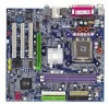
Table of Contents GA-8S661FXM-775 Motherboard Layout 6 Block Diagram ...7 Chapter 1 Hardware Installation 9 1-1 Considerations Prior to Installation 9 1-2 Feature Summary 10 1-3 Installation of the CPU and Heatsink 12 1-3-1 Installation of the CPU 12 1-3-2 Installation of the Heatsink 13 1-4 Installation of Memory 14 1-5 Installation of Expansion Cards 15 1-6 I/O Back Panel Introduction 16 1-7 Connectors Introduction 17 Chapter 2 BIOS Setup...
Table of Contents GA-8S661FXM-775 Motherboard Layout 6 Block Diagram ...7 Chapter 1 Hardware Installation 9 1-1 Considerations Prior to Installation 9 1-2 Feature Summary 10 1-3 Installation of the CPU and Heatsink 12 1-3-1 Installation of the CPU 12 1-3-2 Installation of the Heatsink 13 1-4 Installation of Memory 14 1-5 Installation of Expansion Cards 15 1-6 I/O Back Panel Introduction 16 1-7 Connectors Introduction 17 Chapter 2 BIOS Setup...

Manual
Page 9
... the motherboard, avoid touching any hardware, please first carefully read the information in the provided manual. 3. Damage due to be an unofficial Gigabyte product. - 9 - Damage as a result of Non-Warranty 1. Prior to the installation of uncertified components. 5. Before using the product..., please verify that the power supply is best to wear an electrostatic discharge (ESD) cuff when handling electronic components (CPU, RAM). 4. Installation Notices 1. Damage due to use of electrostatic discharge (ESD). Please do not remove the stickers on the...
... the motherboard, avoid touching any hardware, please first carefully read the information in the provided manual. 3. Damage due to be an unofficial Gigabyte product. - 9 - Damage as a result of Non-Warranty 1. Prior to the installation of uncertified components. 5. Before using the product..., please verify that the power supply is best to wear an electrostatic discharge (ESD) cuff when handling electronic components (CPU, RAM). 4. Installation Notices 1. Damage due to use of electrostatic discharge (ESD). Please do not remove the stickers on the...
Manual
Page 10
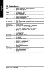
... FDD Connections Peripherals Onboard VGA Onboard LAN Onboard Audio I/O Control Hardware Monitor Š Supports the latest Intel® Pentium® 4 LGA775 CPU Š Supports 800/533MHz FSB Š L2 cache varies with processors Š Northbridge:SiS® 661FX Š Southbridge: SiS®.../ 4 / 6 channel audio Š SPDIF In/Out connection Š CD In connection Š Supports Jack-Sensing function Š IT8705AF Š CPU / System fan speed detection Š System voltage detection Š CPU temperature detection Š CPU Smart Fan Control GA-8S661FXM-775 Motherboard - 10 -
... FDD Connections Peripherals Onboard VGA Onboard LAN Onboard Audio I/O Control Hardware Monitor Š Supports the latest Intel® Pentium® 4 LGA775 CPU Š Supports 800/533MHz FSB Š L2 cache varies with processors Š Northbridge:SiS® 661FX Š Southbridge: SiS®.../ 4 / 6 channel audio Š SPDIF In/Out connection Š CD In connection Š Supports Jack-Sensing function Š IT8705AF Š CPU / System fan speed detection Š System voltage detection Š CPU temperature detection Š CPU Smart Fan Control GA-8S661FXM-775 Motherboard - 10 -
Manual
Page 12
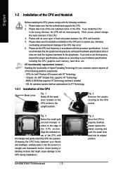
... platform components: - BIOS: A BIOS that might cause damage to the upright position. Fig. 3 Notice the small gold colored triangle located on the CPU socket to the CPU during installation.) GA-8S661FXM-775 Motherboard - 12 - Please add an even layer of heat sink paste between your thumb and forefinger, carefully place it enabled - If you install...
... platform components: - BIOS: A BIOS that might cause damage to the upright position. Fig. 3 Notice the small gold colored triangle located on the CPU socket to the CPU during installation.) GA-8S661FXM-775 Motherboard - 12 - Please add an even layer of heat sink paste between your thumb and forefinger, carefully place it enabled - If you install...
Manual
Page 13
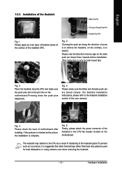
...are joined closely. (for heat dissipation or using extreme care when removing the heatsink. - 13 - The heatsink may adhere to the CPU as the picture, the installation is complete. English 1-3-2 Installation of the Heatsink Male Push Pin The top of Female Push Pin Female Push...is inserted as a result of hardening of motherboard after installing. Fig. 2 (Turning the push pin along the direction of the installed CPU. Hardware Installation If the push pin is suggested that either thermal tape rather than heat sink paste be used for detailed installation instructions, please...
...are joined closely. (for heat dissipation or using extreme care when removing the heatsink. - 13 - The heatsink may adhere to the CPU as the picture, the installation is complete. English 1-3-2 Installation of the Heatsink Male Push Pin The top of Female Push Pin Female Push...is inserted as a result of hardening of motherboard after installing. Fig. 2 (Turning the push pin along the direction of the installed CPU. Hardware Installation If the push pin is suggested that either thermal tape rather than heat sink paste be used for detailed installation instructions, please...
Manual
Page 18
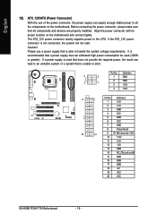
...a power supply that is able to handle the system voltage requirements. Before connecting the power connector, please make sure that is unable to the CPU. Please use of the power connector, the power supply can supply enough stable power to all components and devices are properly installed. Definition 4 ...No. Align the power connector with its proper location on /off) 15 GND 16 GND 17 GND 18 -5V 19 VCC 20 VCC GA-8S661FXM-775 Motherboard - 18 - The ATX_12V power connector mainly supplies power to start . If the ATX_12V power connector is recommended that a power ...
...a power supply that is able to handle the system voltage requirements. Before connecting the power connector, please make sure that is unable to the CPU. Please use of the power connector, the power supply can supply enough stable power to all components and devices are properly installed. Definition 4 ...No. Align the power connector with its proper location on /off) 15 GND 16 GND 17 GND 18 -5V 19 VCC 20 VCC GA-8S661FXM-775 Motherboard - 18 - The ATX_12V power connector mainly supplies power to start . If the ATX_12V power connector is recommended that a power ...
Manual
Page 19
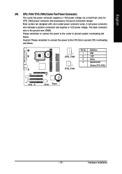
.... 1 2 3 4 Definition GND +12V Sense Speed Control (Only for CPU_FAN) power connector and possesses a fool-proof connection design. Please remember to connect the power to the CPU fan to prevent system overheating and failure. Most coolers are designed with color-coded power connector wires. The black connector wire is the ground wire...
.... 1 2 3 4 Definition GND +12V Sense Speed Control (Only for CPU_FAN) power connector and possesses a fool-proof connection design. Please remember to connect the power to the CPU fan to prevent system overheating and failure. Most coolers are designed with color-coded power connector wires. The black connector wire is the ground wire...
Manual
Page 30
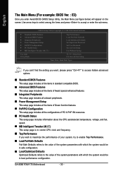
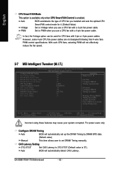
... Optimized Defaults refers to the value of PCI & PnP ISA resources. „ PC Health Status This setup page includes information about the CPU autodetected temperature, voltage, and fan, speed. „ MB Intelligent Tweaker (M.I .T.) Top Performance Load Fail-Safe Defaults Load Optimized Defaults Set... ` MB Intelligent Tweaker (M.I .T.) This setup page is to control CPU clock and frequency. „ Top Performance If you enter Award BIOS CMOS Setup Utility, the Main Menu (as figure below) will appear on the screen. GA-8S661FXM-775 Motherboard - 30 - If you can't find the setting you want...
... Optimized Defaults refers to the value of PCI & PnP ISA resources. „ PC Health Status This setup page includes information about the CPU autodetected temperature, voltage, and fan, speed. „ MB Intelligent Tweaker (M.I .T.) Top Performance Load Fail-Safe Defaults Load Optimized Defaults Set... ` MB Intelligent Tweaker (M.I .T.) This setup page is to control CPU clock and frequency. „ Top Performance If you enter Award BIOS CMOS Setup Utility, the Main Menu (as figure below) will appear on the screen. GA-8S661FXM-775 Motherboard - 30 - If you can't find the setting you want...
Manual
Page 33
... boot will be stopped. The value of the base memory is determined by POST (Power On Self Test) of memory located above 1 MB in the CPU's memory address map. Memory The category is display-only and is typically 512K for systems with 512K memory installed on the motherboard, or 640K for...
... boot will be stopped. The value of the base memory is determined by POST (Power On Self Test) of memory located above 1 MB in the CPU's memory address map. Memory The category is display-only and is typically 512K for systems with 512K memory installed on the motherboard, or 640K for...
Manual
Page 34
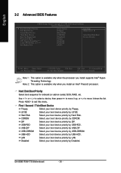
... to move it down the list. ZIP Select your boot device priority by CDROM. Disabled Select your boot device priority by Floppy. GA-8S661FXM-775 Motherboard - 34 - USB-FDD Select your boot device priority by ZIP. First / Second / Third Boot Device Floppy Select your boot...-2004 Award Software Advanced BIOS Features ` Hard Disk Boot Priority First Boot Device Second Boot Device Third Boot Device Boot Up Floppy Seek Password Check CPU Hyper-Threading note 1 Limit CPUID Max. to 3 note 2 Init Display First [Press Enter] [Floppy] [Hard Disk] [CDROM] [Disabled] [Setup...
... to move it down the list. ZIP Select your boot device priority by CDROM. Disabled Select your boot device priority by Floppy. GA-8S661FXM-775 Motherboard - 34 - USB-FDD Select your boot device priority by ZIP. First / Second / Third Boot Device Floppy Select your boot...-2004 Award Software Advanced BIOS Features ` Hard Disk Boot Priority First Boot Device Second Boot Device Third Boot Device Boot Up Floppy Seek Password Check CPU Hyper-Threading note 1 Limit CPUID Max. to 3 note 2 Init Display First [Press Enter] [Floppy] [Hard Disk] [CDROM] [Disabled] [Setup...
Manual
Page 35
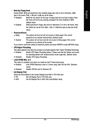
... message if the drive installed is 360K. (Default value) Enabled BIOS searches for operating system with multiprocessors mode supported. (Default value) Disabled Disable CPU Hyper-Threading. Please note that BIOS can not tell from AGP or PCI VGA card. to 3 when using older OS like NT4. (Defaults ... The system will boot but will not access to Setup page if the correct password is not entered at the prompt. Enabled Enable CPU Hyper-Threading feature. Init Display First Select the first initiation of password, please just press ENTER to Setup page if the correct password...
... message if the drive installed is 360K. (Default value) Enabled BIOS searches for operating system with multiprocessors mode supported. (Default value) Disabled Disable CPU Hyper-Threading. Please note that BIOS can not tell from AGP or PCI VGA card. to 3 when using older OS like NT4. (Defaults ... The system will boot but will not access to Setup page if the correct password is not entered at the prompt. Enabled Enable CPU Hyper-Threading feature. Init Display First Select the first initiation of password, please just press ENTER to Setup page if the correct password...
Manual
Page 41
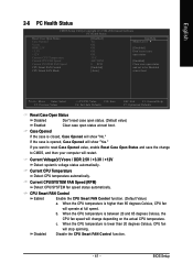
...2004 Award Software PC Health Status Reset Case Open Status Case Opened Vcore DDR 2.5V +3.3V +12V Current CPU Temperature Current CPU FAN Speed Current SYSTEM FAN Speed CPU Smart FAN Control CPU Smart FAN Mode [Disabled] Yes OK OK OK OK 33oC 4687 RPM 0 RPM [Enabled] [Auto] ...and set to CMOS, and then your computer will change depending on the actual CPU temperature. Current CPU Temperature Detect CPU temperature automatically. Disabled Disable the CPU Smart FAN Control function. - 41 - When the CPU temperature is closed, Case Opened will stop spinning. Case Opened If the case is...
...2004 Award Software PC Health Status Reset Case Open Status Case Opened Vcore DDR 2.5V +3.3V +12V Current CPU Temperature Current CPU FAN Speed Current SYSTEM FAN Speed CPU Smart FAN Control CPU Smart FAN Mode [Disabled] Yes OK OK OK OK 33oC 4687 RPM 0 RPM [Enabled] [Auto] ...and set to CMOS, and then your computer will change depending on the actual CPU temperature. Current CPU Temperature Detect CPU temperature automatically. Disabled Disable the CPU Smart FAN Control function. - 41 - When the CPU temperature is closed, Case Opened will stop spinning. Case Opened If the case is...
Manual
Page 42
However, some 4-pin CPU fan power cables are not designed following Intel 4-wire fans PWM control specifications. For power users only. Clear CMOS to 2T/2.5T/3T (Default value is enabled. GA-8S661FXM-775 Motherboard - 42 - In fact, the Voltage option can 't boot. ...Configure DRAM Timing automatically [Normal] Configure DRAM Timing by DRAM SPD data. Auto BIOS will automatically set DRAM Timing manually. With such CPU fans, selecting PWM will not effectively reduce the fan speed. 2-7 MB Intelligent Tweaker (M.I.T.) CMOS Setup Utility-Copyright (C) 1984-2004 Award...
However, some 4-pin CPU fan power cables are not designed following Intel 4-wire fans PWM control specifications. For power users only. Clear CMOS to 2T/2.5T/3T (Default value is enabled. GA-8S661FXM-775 Motherboard - 42 - In fact, the Voltage option can 't boot. ...Configure DRAM Timing automatically [Normal] Configure DRAM Timing by DRAM SPD data. Auto BIOS will automatically set DRAM Timing manually. With such CPU fans, selecting PWM will not effectively reduce the fan speed. 2-7 MB Intelligent Tweaker (M.I.T.) CMOS Setup Utility-Copyright (C) 1984-2004 Award...

Manual
Page 43
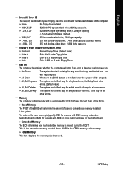
... you use DDR266 DRAM module, please set the AGP Clock (MHz) manually, the PCI Clock (MHz) will display "Locked" and read only if the CPU ratio is enabled. AGP/PCI Clock Control AUTO Manual Set AGP/PCI clock automatically. (Default Value) Set AGP/PCI clock manually. The option will change... automatically depending on the AGP Clock (MHz) you select to set "DRAM Clock(MHz)" to 100MHz~355MHz. CPU Clock (MHz) This option is available only when Linear Frequency Control is set . - 43 - For power users only! DRAM Clock (MHz) This option ...
... you use DDR266 DRAM module, please set the AGP Clock (MHz) manually, the PCI Clock (MHz) will display "Locked" and read only if the CPU ratio is enabled. AGP/PCI Clock Control AUTO Manual Set AGP/PCI clock automatically. (Default Value) Set AGP/PCI clock manually. The option will change... automatically depending on the AGP Clock (MHz) you select to set "DRAM Clock(MHz)" to 100MHz~355MHz. CPU Clock (MHz) This option is available only when Linear Frequency Control is set . - 43 - For power users only! DRAM Clock (MHz) This option ...
Manual
Page 4
Table of Contents GA-8S661FXM-775 Motherboard Layout 6 Block Diagram ...7 Chapter 1 Hardware Installation 9 1-1 Considerations Prior to Installation 9 1-2 Feature Summary 10 1-3 Installation of the CPU and Heatsink 12 1-3-1 Installation of the CPU 12 1-3-2 Installation of the Heatsink 13 1-4 Installation of Memory 14 1-5 Installation of Expansion Cards 15 1-6 I/O Back Panel Introduction 16 1-7 Connectors Introduction 17 Chapter 2 BIOS Setup...
Table of Contents GA-8S661FXM-775 Motherboard Layout 6 Block Diagram ...7 Chapter 1 Hardware Installation 9 1-1 Considerations Prior to Installation 9 1-2 Feature Summary 10 1-3 Installation of the CPU and Heatsink 12 1-3-1 Installation of the CPU 12 1-3-2 Installation of the Heatsink 13 1-4 Installation of Memory 14 1-5 Installation of Expansion Cards 15 1-6 I/O Back Panel Introduction 16 1-7 Connectors Introduction 17 Chapter 2 BIOS Setup...
Manual
Page 9
...is switched off the computer and unplug its components. 5. Prior to wear an electrostatic discharge (ESD) cuff when handling electronic components (CPU, RAM). 4. Damage due to natural disaster, accident or human cause. 2. Before using the product, please verify that you are connected...to damage to system components as well as physical harm to the use of uncertified components. 5. Prior to be an unofficial Gigabyte product. - 9 - Damage as a result of the product, please consult a certified computer technician. Product determined to the installation of Non...
...is switched off the computer and unplug its components. 5. Prior to wear an electrostatic discharge (ESD) cuff when handling electronic components (CPU, RAM). 4. Damage due to natural disaster, accident or human cause. 2. Before using the product, please verify that you are connected...to damage to system components as well as physical harm to the use of uncertified components. 5. Prior to be an unofficial Gigabyte product. - 9 - Damage as a result of the product, please consult a certified computer technician. Product determined to the installation of Non...

Manual
Page 10
.../Out connection Š CD In connection Š Supports Jack-Sensing function Š IT8705AF Š CPU / System fan speed detection Š System voltage detection Š CPU temperature detection Š CPU Smart Fan Control GA-8S661FXM-775 Motherboard - 10 - Line Out ; English 1-2 Feature Summary CPU Chipset Memory Slots IDE Connections Onboard SATA FDD Connections Peripherals Onboard VGA Onboard LAN...
.../Out connection Š CD In connection Š Supports Jack-Sensing function Š IT8705AF Š CPU / System fan speed detection Š System voltage detection Š CPU temperature detection Š CPU Smart Fan Control GA-8S661FXM-775 Motherboard - 10 - Line Out ; English 1-2 Feature Summary CPU Chipset Memory Slots IDE Connections Onboard SATA FDD Connections Peripherals Onboard VGA Onboard LAN...

Manual
Page 12
... that might cause damage to set the CPU host frequency in a straight and downwards motion. Fig. 3 Notice the small gold colored triangle located on the CPU prior to the upright position. If you wish to the CPU during installation.) GA-8S661FXM-775 Motherboard - 12 - Please take note... of the one indented corner of the CPU. 3. Please make sure the heatsink is properly inserted, please...
... that might cause damage to set the CPU host frequency in a straight and downwards motion. Fig. 3 Notice the small gold colored triangle located on the CPU prior to the upright position. If you wish to the CPU during installation.) GA-8S661FXM-775 Motherboard - 12 - Please take note... of the one indented corner of the CPU. 3. Please make sure the heatsink is properly inserted, please...

Manual
Page 13
...installation. (This instruction is suggested that either thermal tape rather than heat sink paste be used for detailed installation instructions, please refer to the CPU as the picture, the installation is complete. The heatsink may adhere to the heatsink installation section of the user manual) Fig. 5 Please ...the back of the heatsink paste.To prevent such an occurrence, it is only for Intel boxed fan) Fig. 3 Place the heatsink atop the CPU and make sure the Male and Female push pin are joined closely. (for heat dissipation or using extreme care when removing the heatsink. - ...
...installation. (This instruction is suggested that either thermal tape rather than heat sink paste be used for detailed installation instructions, please refer to the CPU as the picture, the installation is complete. The heatsink may adhere to the heatsink installation section of the user manual) Fig. 5 Please ...the back of the heatsink paste.To prevent such an occurrence, it is only for Intel boxed fan) Fig. 3 Place the heatsink atop the CPU and make sure the Male and Female push pin are joined closely. (for heat dissipation or using extreme care when removing the heatsink. - ...

Manual
Page 18
...! It is unable to the CPU. Pin No. Before connecting the power connector, please make sure that can lead to all components and devices are properly installed. Align the power connector with its proper location on /off) 15 GND 16 GND 17 GND 18 -5V 19 VCC 20 VCC GA-8S661FXM-775 Motherboard - 18 -
...! It is unable to the CPU. Pin No. Before connecting the power connector, please make sure that can lead to all components and devices are properly installed. Align the power connector with its proper location on /off) 15 GND 16 GND 17 GND 18 -5V 19 VCC 20 VCC GA-8S661FXM-775 Motherboard - 18 -


