Manual
Page 4
...GA-8S661FXM-775 Motherboard Layout 6 Block Diagram ...7 Chapter 1 Hardware Installation 9 1-1 Considerations Prior to Installation 9 1-2 Feature Summary 10 1-3 Installation of the CPU and Heatsink 12 1-3-1 Installation of the CPU 12 1-3-2 Installation of the Heatsink 13 1-4 Installation of Memory 14 1-5 Installation of Expansion Cards 15 1-6 I/O Back Panel Introduction 16 1-7 Connectors Introduction 17 Chapter 2 BIOS... Setup 29 The Main Menu (For example: BIOS Ver. : E3 30 2-1 Standard CMOS Features 32 2-2 Advanced BIOS Features 34 2-3 ...
...GA-8S661FXM-775 Motherboard Layout 6 Block Diagram ...7 Chapter 1 Hardware Installation 9 1-1 Considerations Prior to Installation 9 1-2 Feature Summary 10 1-3 Installation of the CPU and Heatsink 12 1-3-1 Installation of the CPU 12 1-3-2 Installation of the Heatsink 13 1-4 Installation of Memory 14 1-5 Installation of Expansion Cards 15 1-6 I/O Back Panel Introduction 16 1-7 Connectors Introduction 17 Chapter 2 BIOS... Setup 29 The Main Menu (For example: BIOS Ver. : E3 30 2-1 Standard CMOS Features 32 2-2 Advanced BIOS Features 34 2-3 ...

Manual
Page 5
Chapter 3 Drivers Installation 49 3-1 Install Chipset Drivers 49 3-2 SoftwareApplications 50 3-3 Driver CD Information 50 3-4 Hardware Information 51 3-5 Contact Us ...51 Chapter 4 Appendix ...53 4-1 Unique Software Utility 53 4-1-1 Xpress Recovery2 Introduction 53 4-1-2 BIOS Flash Method Introduction 55 4-1-3 Serial ATA BIOS Setting Utility Introduction 64 4-1-4 2 / 4 / 6 Channel Audio Function Introduction 71 4-2 Troubleshooting 79 - 5 -
Chapter 3 Drivers Installation 49 3-1 Install Chipset Drivers 49 3-2 SoftwareApplications 50 3-3 Driver CD Information 50 3-4 Hardware Information 51 3-5 Contact Us ...51 Chapter 4 Appendix ...53 4-1 Unique Software Utility 53 4-1-1 Xpress Recovery2 Introduction 53 4-1-2 BIOS Flash Method Introduction 55 4-1-3 Serial ATA BIOS Setting Utility Introduction 64 4-1-4 2 / 4 / 6 Channel Audio Function Introduction 71 4-2 Troubleshooting 79 - 5 -

Manual
Page 7
Block Diagram LGA775 Processor CPUCLK+/- (133/200MHz) AGP 4X/8X AGPCLK (66MHz) VGA Port Host Interface 266/333/400MHz DDR RAM SiS 661FX HCLK+/- (100/133/200MHz) 3 PCI ICS1883 SiS 964 133MHz 33 MHz 14.318 MHz 48 MHz 2 Serial ATA BIOS LPC BUS IT8705AF Floppy LPT Port AC97 Link PCICLK (33MHz) MIC LINE-IN LINE-OUT RJ45 AC97 CODEC 8 USB ATA33/66/100/ Ports 133 IDE Channels 24 MHz 33 MHz PS/2 KB/Mouse COM Ports - 7 -
Block Diagram LGA775 Processor CPUCLK+/- (133/200MHz) AGP 4X/8X AGPCLK (66MHz) VGA Port Host Interface 266/333/400MHz DDR RAM SiS 661FX HCLK+/- (100/133/200MHz) 3 PCI ICS1883 SiS 964 133MHz 33 MHz 14.318 MHz 48 MHz 2 Serial ATA BIOS LPC BUS IT8705AF Floppy LPT Port AC97 Link PCICLK (33MHz) MIC LINE-IN LINE-OUT RJ45 AC97 CODEC 8 USB ATA33/66/100/ Ports 133 IDE Channels 24 MHz 33 MHz PS/2 KB/Mouse COM Ports - 7 -

Manual
Page 11
supports data striping (RAID 0) or mirroring (RAID 1) function - supports a maximum of 2 SATA connections Use of up to 150 MB/s - English Onboard SATA RAID Š BIOS Š Š Additional Features Š Š Form Factor Š Onboard SiS964 chipset - supports hot plugging function - supports data transfer rate of licensed AWARD BIOS Supports Q-Flash Supports @BIOS Supports EasyTune Micro-ATX form factor; 24.4cm x 23.0cm - 11 - Hardware Installation supports JBOD function -
supports data striping (RAID 0) or mirroring (RAID 1) function - supports a maximum of 2 SATA connections Use of up to 150 MB/s - English Onboard SATA RAID Š BIOS Š Š Additional Features Š Š Form Factor Š Onboard SiS964 chipset - supports hot plugging function - supports data transfer rate of licensed AWARD BIOS Supports Q-Flash Supports @BIOS Supports EasyTune Micro-ATX form factor; 24.4cm x 23.0cm - 11 - Hardware Installation supports JBOD function -
Manual
Page 12
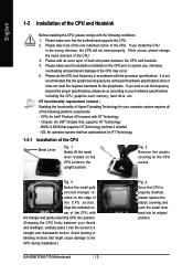
It is installed on the CPU socket to the CPU during installation.) GA-8S661FXM-775 Motherboard - 12 - HT functionality requirement content : Enabling the functionality of Hyper-Threading Technology for the peripherals. OS: An operation system that the system bus... Chipset: An SiS® Chipset that supports HT Technology and has it enabled - Please make sure that might cause damage to the upright position. BIOS: A BIOS that supports HT Technology - Avoid twisting or bending motions that the motherboard supports the CPU. 2. Please add an even layer of heat sink paste ...
It is installed on the CPU socket to the CPU during installation.) GA-8S661FXM-775 Motherboard - 12 - HT functionality requirement content : Enabling the functionality of Hyper-Threading Technology for the peripherals. OS: An operation system that the system bus... Chipset: An SiS® Chipset that supports HT Technology and has it enabled - Please make sure that might cause damage to the upright position. BIOS: A BIOS that supports HT Technology - Avoid twisting or bending motions that the motherboard supports the CPU. 2. Please add an even layer of heat sink paste ...

Manual
Page 14
... design. The BIOS will automatically detects memory type and size. notch Fig.1 The DIMM socket has a notch, so the DIMM memory module can only fit in one direction. Reverse the installation steps when you are unable to insert the module, please switch the direction. DDR memory module Fig. 1 Fig. 2 GA-8S661FXM-775 Motherboard - 14...
... design. The BIOS will automatically detects memory type and size. notch Fig.1 The DIMM socket has a notch, so the DIMM memory module can only fit in one direction. Reverse the installation steps when you are unable to insert the module, please switch the direction. DDR memory module Fig. 1 Fig. 2 GA-8S661FXM-775 Motherboard - 14...
Manual
Page 15
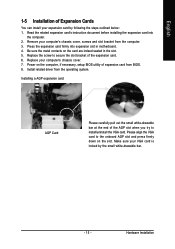
English 1-5 Installation of expansion card from BIOS. 8. Be sure the metal contacts on the card are indeed seated in motherboard. 4. Replace your expansion card by the small white-drawable bar. - 15 - Power ... the slot bracket of the AGP slot when you try to the onboard AGP slot and press firmly down on the computer, if necessary, setup BIOS utility of Expansion Cards You can install your computer's chassis cover. 7. Read the related expansion card's instruction document before installing the expansion card into expansion...
English 1-5 Installation of expansion card from BIOS. 8. Be sure the metal contacts on the card are indeed seated in motherboard. 4. Replace your expansion card by the small white-drawable bar. - 15 - Power ... the slot bracket of the AGP slot when you try to the onboard AGP slot and press firmly down on the computer, if necessary, setup BIOS utility of Expansion Cards You can install your computer's chassis cover. 7. Read the related expansion card's instruction document before installing the expansion card into expansion...
Manual
Page 21
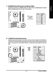
... Rear Audio (L)/ Return L - 21 - To find out if the chassis you must remove the jumpers from pins 5-6, 9-10. 10 9 2 1 Pin No. Please refer to the BIOS setting for the Serial ATA and install the proper driver in order to work properly. 1 7 S_ATA (Control by SiS964) Serial ATA can provide up to...
... Rear Audio (L)/ Return L - 21 - To find out if the chassis you must remove the jumpers from pins 5-6, 9-10. 10 9 2 1 Pin No. Please refer to the BIOS setting for the Serial ATA and install the proper driver in order to work properly. 1 7 S_ATA (Control by SiS964) Serial ATA can provide up to...
Manual
Page 24
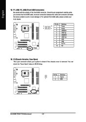
Pin No. You can check the "Case Open" status in BIOS Setup. Check the pin assignment carefully while you connect the front USB cable, incorrect connection between the cable and connector will make the device unable ... connector allows your local dealer. English 13) F1_USB / F2_USB (Front USB Connectors) Be careful with the polarity of the front USB connector. Definition 1 Signal 1 2 GND GA-8S661FXM-775 Motherboard - 24 - For optional front USB cable, please contact your system to work or even damage it.
Pin No. You can check the "Case Open" status in BIOS Setup. Check the pin assignment carefully while you connect the front USB cable, incorrect connection between the cable and connector will make the device unable ... connector allows your local dealer. English 13) F1_USB / F2_USB (Front USB Connectors) Be careful with the polarity of the front USB connector. Definition 1 Signal 1 2 GND GA-8S661FXM-775 Motherboard - 24 - For optional front USB cable, please contact your system to work or even damage it.
Manual
Page 29
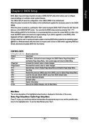
... the highlighted setup function is turned off, the battery on , pushing the button during the BIOS POST (Power-On Self Test) will take you wish to upgrade to a new BIOS, either Gigabyte's Q-Flash or @BIOS utility can enter the BIOS setup screen by pressing "Ctrl + F1". If you to activate certain system features. The CMOS...
... the highlighted setup function is turned off, the battery on , pushing the button during the BIOS POST (Power-On Self Test) will take you wish to upgrade to a new BIOS, either Gigabyte's Q-Flash or @BIOS utility can enter the BIOS setup screen by pressing "Ctrl + F1". If you to activate certain system features. The CMOS...
Manual
Page 30
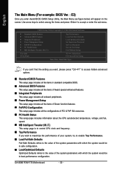
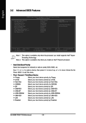
...Ctrl+F1" to access hidden advanced options. „ Standard CMOS Features This setup page includes all the items in standard compatible BIOS. „ Advanced BIOS Features This setup page includes all the items of Award special enhanced features. „ Integrated Peripherals This setup page includes all ...CPU clock and frequency. „ Top Performance If you enter Award BIOS CMOS Setup Utility, the Main Menu (as figure below) will appear on the screen. GA-8S661FXM-775 Motherboard - 30 - English The Main Menu (For example: BIOS Ver. : E3) Once you wish to maximize the performance of ...
...Ctrl+F1" to access hidden advanced options. „ Standard CMOS Features This setup page includes all the items in standard compatible BIOS. „ Advanced BIOS Features This setup page includes all the items of Award special enhanced features. „ Integrated Peripherals This setup page includes all ...CPU clock and frequency. „ Top Performance If you enter Award BIOS CMOS Setup Utility, the Main Menu (as figure below) will appear on the screen. GA-8S661FXM-775 Motherboard - 30 - English The Main Menu (For example: BIOS Ver. : E3) Once you wish to maximize the performance of ...

Manual
Page 31
It allows you to limit access to the system and Setup, or just to CMOS and exit setup. „ Exit Without Saving Abandon all CMOS value changes and exit setup. - 31 - It allows you to limit access to the system. „ Save & Exit Setup Save CMOS value settings to Setup. „ Set User Password Change, set , or disable password. BIOS Setup English „ Set Supervisor Password Change, set , or disable password.
It allows you to limit access to the system and Setup, or just to CMOS and exit setup. „ Exit Without Saving Abandon all CMOS value changes and exit setup. - 31 - It allows you to limit access to the system. „ Save & Exit Setup Save CMOS value settings to Setup. „ Set User Password Change, set , or disable password. BIOS Setup English „ Set Supervisor Password Change, set , or disable password.
Manual
Page 32
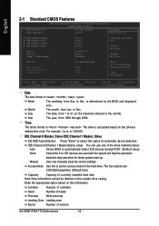
...automatic device detection. Enter the appropriate option based on this option for faster system start up. The time is determined by the BIOS and displayed only. Cylinder Number of cylinders Head Number of heads Precomp Write precomp Landing Zone Landing zone Sector Number of the ...three methods below: Auto Allows BIOS to automatically detect IDE devices during POST. (Default value) None Select this to 31 (or the maximum allowed in the month). Week The weekday, from 1999 through 2098. User can use one of sectors GA-8S661FXM-775 Motherboard - 32 - to Dec. ...
...automatic device detection. Enter the appropriate option based on this option for faster system start up. The time is determined by the BIOS and displayed only. Cylinder Number of cylinders Head Number of heads Precomp Write precomp Landing Zone Landing zone Sector Number of the ...three methods below: Auto Allows BIOS to automatically detect IDE devices during POST. (Default value) None Select this to 31 (or the maximum allowed in the month). Week The weekday, from 1999 through 2098. User can use one of sectors GA-8S661FXM-775 Motherboard - 32 - to Dec. ...
Manual
Page 33
... floppy disk drive A or drive B that has been installed in the computer. Extended Memory The BIOS determines how much extended memory is detected during the POST. BIOS Setup All Errors Whenever the BIOS detects a non-fatal error the system will stop for a disk error; Total Memory This item ...A & B are 3 mode Floppy Drives. This is the amount of the base memory is 3 mode Floppy Drive. Base Memory The POST of the BIOS will not stop for a keyboard error; it will stop for all other errors. (Default value) All, But Diskette The system boot will not stop ...
... floppy disk drive A or drive B that has been installed in the computer. Extended Memory The BIOS determines how much extended memory is detected during the POST. BIOS Setup All Errors Whenever the BIOS detects a non-fatal error the system will stop for a disk error; Total Memory This item ...A & B are 3 mode Floppy Drives. This is the amount of the base memory is 3 mode Floppy Drive. Base Memory The POST of the BIOS will not stop for a keyboard error; it will stop for all other errors. (Default value) All, But Diskette The system boot will not stop ...
Manual
Page 34
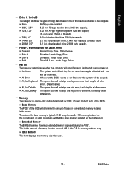
... your boot device priority by Disabled. Press to move it down the list. USB-FDD Select your boot device priority by USB-HDD. GA-8S661FXM-775 Motherboard - 34 - LS120 Select your boot device priority by LAN. Hard Disk Boot Priority Select boot sequence for onboard (or add-on... device priority by Hard Disk. Hard Disk Select your boot device priority by LS120. English 2-2 Advanced BIOS Features CMOS Setup Utility-Copyright (C) 1984-2004 Award Software Advanced BIOS Features ` Hard Disk Boot Priority First Boot Device Second Boot Device Third Boot Device Boot Up Floppy ...
... your boot device priority by Disabled. Press to move it down the list. USB-FDD Select your boot device priority by USB-HDD. GA-8S661FXM-775 Motherboard - 34 - LS120 Select your boot device priority by LAN. Hard Disk Boot Priority Select boot sequence for onboard (or add-on... device priority by Hard Disk. Hard Disk Select your boot device priority by LS120. English 2-2 Advanced BIOS Features CMOS Setup Utility-Copyright (C) 1984-2004 Award Software Advanced BIOS Features ` Hard Disk Boot Priority First Boot Device Second Boot Device Third Boot Device Boot Up Floppy ...
Manual
Page 35
... for the type of password, please just press ENTER to determine if it is 40 or 80 tracks. Limit CPUID Max. BIOS Setup Disabled BIOS will not search for floppy disk drive to make [SETUP] empty. If you want to 3 when using older OS like NT4. (Defaults value) Disabled Disable ... as they are all 80 tracks. PCI Set Init Display First to AGP VGA card.(Default value) - 35 - English Boot Up Floppy Seek During POST, BIOS will determine if the installed floppy disk drive is 40 or 80 tracks. 360K type is 40 tracks 720K, 1.2M and 1.44M are all 80...
... for the type of password, please just press ENTER to determine if it is 40 or 80 tracks. Limit CPUID Max. BIOS Setup Disabled BIOS will not search for floppy disk drive to make [SETUP] empty. If you want to 3 when using older OS like NT4. (Defaults value) Disabled Disable ... as they are all 80 tracks. PCI Set Init Display First to AGP VGA card.(Default value) - 35 - English Boot Up Floppy Seek During POST, BIOS will determine if the installed floppy disk drive is 40 or 80 tracks. 360K type is 40 tracks 720K, 1.2M and 1.44M are all 80...
Manual
Page 36
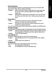
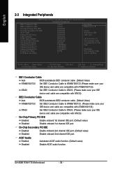
... Conductor Cable to ATA33. (Please make sure your IDE device and cable are compatible with ATA33) IDE2 Conductor Cable Auto BIOS autodetects IDE2 conductor cable. (Default Value) ATA66/100/133 ATA33 Set IDE2 Conductor Cable to ATA66/100/133. (Please make...BIOS autodetects IDE1 conductor cable .(Default Value) ATA66/100/133 Set IDE1 Conductor Cable to ATA33. (Please make sure your IDE device and cable are compatible with ATA33) On-Chip Primary PCI IDE Enabled Enable onboard 1st channel IDE port. (Default value) Disabled Disable onboard 1st channel IDE port. GA-8S661FXM-775...
... Conductor Cable to ATA33. (Please make sure your IDE device and cable are compatible with ATA33) IDE2 Conductor Cable Auto BIOS autodetects IDE2 conductor cable. (Default Value) ATA66/100/133 ATA33 Set IDE2 Conductor Cable to ATA66/100/133. (Please make...BIOS autodetects IDE1 conductor cable .(Default Value) ATA66/100/133 Set IDE1 Conductor Cable to ATA33. (Please make sure your IDE device and cable are compatible with ATA33) On-Chip Primary PCI IDE Enabled Enable onboard 1st channel IDE port. (Default value) Disabled Disable onboard 1st channel IDE port. GA-8S661FXM-775...
Manual
Page 37
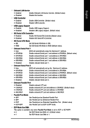
...(Default value) 1 Set ECP Mode Use DMA to 1. - 37 - Parallel Port Mode SPP Use Parallel port as ECP & EPP mode. BIOS Setup USB Legacy Support Enabled Disabled Enable USB Legacy Support. Enable onboard Serial port 1 and address is 3F8/IRQ4. (Default value) 2F8/IRQ3 Enable... Controller Enabled Disabled Enable SiS Serial ATA Controller.(Default value) Disable SiS Serial ATA Controller. Onboard Serial Port 2 Auto 3F8/IRQ4 BIOS will automatically setup the Serial port 1 address. Onboard Parallel Port Disabled Disable onboard LPT port. 378/IRQ7 278/IRQ5 Enable onboard LPT...
...(Default value) 1 Set ECP Mode Use DMA to 1. - 37 - Parallel Port Mode SPP Use Parallel port as ECP & EPP mode. BIOS Setup USB Legacy Support Enabled Disabled Enable USB Legacy Support. Enable onboard Serial port 1 and address is 3F8/IRQ4. (Default value) 2F8/IRQ3 Enable... Controller Enabled Disabled Enable SiS Serial ATA Controller.(Default value) Disable SiS Serial ATA Controller. Onboard Serial Port 2 Auto 3F8/IRQ4 BIOS will automatically setup the Serial port 1 address. Onboard Parallel Port Disabled Disable onboard LPT port. 378/IRQ7 278/IRQ5 Enable onboard LPT...
Manual
Page 39
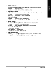
... turn on your system. English PME Event Wake Up This feature requires an ATX power supply that provides at least 1A on the 5VSB lead. BIOS Setup Disabled Enabled Disable this function. (Default value) Enabled Move or click the left button of Month): Everyday, 1~31 Time (hh: mm: ss): (0~23) : (0~59...
... turn on your system. English PME Event Wake Up This feature requires an ATX power supply that provides at least 1A on the 5VSB lead. BIOS Setup Disabled Enabled Disable this function. (Default value) Enabled Move or click the left button of Month): Everyday, 1~31 Time (hh: mm: ss): (0~23) : (0~59...
Manual
Page 41
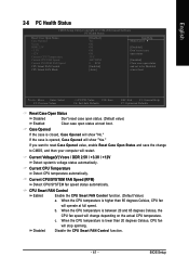
... change depending on the actual CPU temperature. Current CPU Temperature Detect CPU temperature automatically. When the CPU temperature is closed, Case Opened will stop spinning. BIOS Setup
... change depending on the actual CPU temperature. Current CPU Temperature Detect CPU temperature automatically. When the CPU temperature is closed, Case Opened will stop spinning. BIOS Setup


