Manual
Page 1
GA-8IP775 Series Intel® Pentium® 4 LGA775 Processor Motherboard User's Manual Rev. 1003 12ME-8IP775-1003
GA-8IP775 Series Intel® Pentium® 4 LGA775 Processor Motherboard User's Manual Rev. 1003 12ME-8IP775-1003
Manual
Page 2
Motherboard GA-8IP775/GA-8IP775-G Sep. 10, 2004 Motherboard GA-8IP775/GA-8IP775-G Sep. 10, 2004
Motherboard GA-8IP775/GA-8IP775-G Sep. 10, 2004 Motherboard GA-8IP775/GA-8IP775-G Sep. 10, 2004
Manual
Page 4
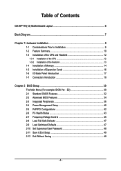
Table of Contents GA-8IP775(-G) Motherboard Layout 6 Block Diagram ...7 Chapter 1 Hardware Installation 9 1-1 Considerations Prior to Installation 9 1-2 Feature Summary 10 1-3 Installation of the CPU and Heatsink 12 1-3-1 Installation of the CPU 12 1-3-2 ...
Table of Contents GA-8IP775(-G) Motherboard Layout 6 Block Diagram ...7 Chapter 1 Hardware Installation 9 1-1 Considerations Prior to Installation 9 1-2 Feature Summary 10 1-3 Installation of the CPU and Heatsink 12 1-3-1 Installation of the CPU 12 1-3-2 ...
Manual
Page 6
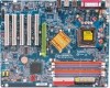
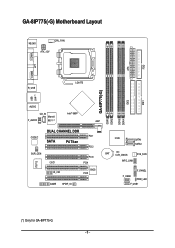
GA-8IP775(-G) Motherboard Layout KB_MS CPU_FAN ATX_12V COMA FDD ATX COMB LPT R_USB LGA775 IDE1 IDE2 GA-8IP775(-G) DDR1 DDR2 USB LAN (*) AUDIO CD_IN Intel® 865P Marvell F_AUDIO 8001 (*) AGP DDR4 DDR3 IT8712 CODEC SUR_CEN DUAL CHANNEL DDR PCI1 SATA P4 Titan PCI2 CI IR_CIR PCI3 PCI4 BIOS PCI5 GAME SPDIF_IO ICH5 SATA1 SATA0 BAT CLR_CMOS SYS_FAN INFO_LINK F_PANEL F_USB2 PWR_LED F_USB1 (*) Only for GA-8IP775-G. - 6 -
GA-8IP775(-G) Motherboard Layout KB_MS CPU_FAN ATX_12V COMA FDD ATX COMB LPT R_USB LGA775 IDE1 IDE2 GA-8IP775(-G) DDR1 DDR2 USB LAN (*) AUDIO CD_IN Intel® 865P Marvell F_AUDIO 8001 (*) AGP DDR4 DDR3 IT8712 CODEC SUR_CEN DUAL CHANNEL DDR PCI1 SATA P4 Titan PCI2 CI IR_CIR PCI3 PCI4 BIOS PCI5 GAME SPDIF_IO ICH5 SATA1 SATA0 BAT CLR_CMOS SYS_FAN INFO_LINK F_PANEL F_USB2 PWR_LED F_USB1 (*) Only for GA-8IP775-G. - 6 -
Manual
Page 9
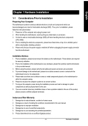
... to use of electrostatic discharge (ESD). English Chapter 1 Hardware Installation 1-1 Considerations Prior to Installation Preparing Your Computer The motherboard contains numerous delicate electronic circuits and components which can lead to damage to system components as well as physical harm to...information in the user manual. 3. Product determined to installation, please follow the instructions below: 1. Thus, prior to be an unofficial Gigabyte product. - 9 - Installation Notices 1. Please make sure there are uncertain about any metal leads or connectors. 3. Instances of the...
... to use of electrostatic discharge (ESD). English Chapter 1 Hardware Installation 1-1 Considerations Prior to Installation Preparing Your Computer The motherboard contains numerous delicate electronic circuits and components which can lead to damage to system components as well as physical harm to...information in the user manual. 3. Product determined to installation, please follow the instructions below: 1. Thus, prior to be an unofficial Gigabyte product. - 9 - Installation Notices 1. Please make sure there are uncertain about any metal leads or connectors. 3. Instances of the...
Manual
Page 10
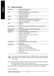
English 1-2 Feature Summary M otherboard CPU Chip set Mem ory Slo ts IDE Connections FDD Connections Onboard SATA Peripherals Onboard LAN (*) Onboard Audio w GA-8IP775 Series Motherboard: GA-8IP 775-G/GA-8 IP775 w Supports the latest Intel® Pentium® 4 LGA775 CPU w Supports 800/533MHz FSB w L2 cache varies with CPU w Northbridge: Intel® 865P w Southbridge: ... lim itation, a FSB 800 Pentium 4 processor will automatically adjust to DDR400. (*) Only for system usage and therefore the actual memory size is reserved for GA-8IP775-G. GA-8IP775 Series Motherboard - 10 -
English 1-2 Feature Summary M otherboard CPU Chip set Mem ory Slo ts IDE Connections FDD Connections Onboard SATA Peripherals Onboard LAN (*) Onboard Audio w GA-8IP775 Series Motherboard: GA-8IP 775-G/GA-8 IP775 w Supports the latest Intel® Pentium® 4 LGA775 CPU w Supports 800/533MHz FSB w L2 cache varies with CPU w Northbridge: Intel® 865P w Southbridge: ... lim itation, a FSB 800 Pentium 4 processor will automatically adjust to DDR400. (*) Only for system usage and therefore the actual memory size is reserved for GA-8IP775-G. GA-8IP775 Series Motherboard - 10 -
Manual
Page 12
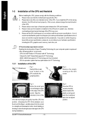
... is not recommended that supports HT Technology - If this occurs, please change the insert direction of the CPU. BIOS: A BIOS that the motherboard supports the CPU. 2. Please make sure the heatsink is installed on the CPU socket. Fig. 2 Rem ov e the pl astic covering on...located on the edge of the CPU socket. Please set beyond the proper specifications, please do so according to the CPU during installation.) GA-8IP775 Series Motherboard - 12 - It is properly inserted, please replace the plastic covering and push the m etal lever back into its original position. ...
... is not recommended that supports HT Technology - If this occurs, please change the insert direction of the CPU. BIOS: A BIOS that the motherboard supports the CPU. 2. Please make sure the heatsink is installed on the CPU socket. Fig. 2 Rem ov e the pl astic covering on...located on the edge of the CPU socket. Please set beyond the proper specifications, please do so according to the CPU during installation.) GA-8IP775 Series Motherboard - 12 - It is properly inserted, please replace the plastic covering and push the m etal lever back into its original position. ...
Manual
Page 14
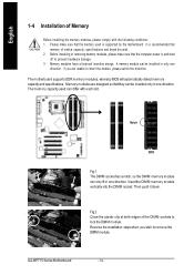
... edges of the DIMM sockets to remove the DIMM module. Insert the DIM M memory module vertically into the DIMM socket. GA-8IP775 Series Motherboard - 14 - Memory modules are unable to prevent hardware damage. 3. Before installing or removing memory modules, please make sure ...that memory of Memory Before installing the memory modules, please comply with each slot. The motherboard supports DDR memory modules, whereby BIOS will automatically detect memory capacity and specifications. Memory modules have a foolproof insertion design. If...
... edges of the DIMM sockets to remove the DIMM module. Insert the DIM M memory module vertically into the DIMM socket. GA-8IP775 Series Motherboard - 14 - Memory modules are unable to prevent hardware damage. 3. Before installing or removing memory modules, please make sure ...that memory of Memory Before installing the memory modules, please comply with each slot. The motherboard supports DDR memory modules, whereby BIOS will automatically detect memory capacity and specifications. Memory modules have a foolproof insertion design. If...
Manual
Page 16
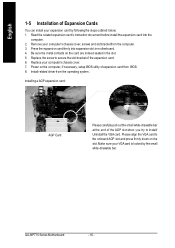
... driver from BIOS. 8. Installing a AGP expansion card: AGP Card Please carefully pull out the small white-drawable bar at the end of the expansion card. 6. GA-8IP775 Series Motherboard - 16 - Press the expansion card firmly into the com puter. 2. Be sure the metal contacts on the card are indeed seated in... motherboard. 4. Power on the slot .Make sure your expansion card by the small white-drawable bar. Please align the VGA card to install/ Uninstall the VGA...
... driver from BIOS. 8. Installing a AGP expansion card: AGP Card Please carefully pull out the small white-drawable bar at the end of the expansion card. 6. GA-8IP775 Series Motherboard - 16 - Press the expansion card firmly into the com puter. 2. Be sure the metal contacts on the card are indeed seated in... motherboard. 4. Power on the slot .Make sure your expansion card by the small white-drawable bar. Please align the VGA card to install/ Uninstall the VGA...

Manual
Page 18
English 1-7 Connectors Introduction 3 1 12 10 11 18 14 16 13 20 6 2 5 19 7 4 17 9 8 15 1) ATX_12V 2) ATX 3) CPU_FAN 4) SYS_FAN 5) IDE1/IDE2 6) FDD 7) SATA0/SATA1 8) PWR_LED 9) F_PANEL 10) F_AUDIO 11) SUR_CEN 12) CD_IN 13) SPDIF_IO 14) IR_CIR 15) F_USB1/F_USB2 16) GAME 17) INFO_LINK 18) CI 19) CLR_CMOS 20) BAT GA-8IP775 Series Motherboard - 18 -
English 1-7 Connectors Introduction 3 1 12 10 11 18 14 16 13 20 6 2 5 19 7 4 17 9 8 15 1) ATX_12V 2) ATX 3) CPU_FAN 4) SYS_FAN 5) IDE1/IDE2 6) FDD 7) SATA0/SATA1 8) PWR_LED 9) F_PANEL 10) F_AUDIO 11) SUR_CEN 12) CD_IN 13) SPDIF_IO 14) IR_CIR 15) F_USB1/F_USB2 16) GAME 17) INFO_LINK 18) CI 19) CLR_CMOS 20) BAT GA-8IP775 Series Motherboard - 18 -
Manual
Page 19
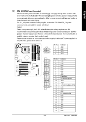
... No. Definition 1 GND 3 4 2 GND 1 2 3 +12V 4 +12V 13 24 - 19 - Otherwise, please do not remove it. Align the power connector with its proper location on the motherboard before plugging in while theATX power supplier is not connected, the system will not start . Please remove the sticker on the... motherboard and connect tightly. Pin No. Please use of the power connector, the power supply can withstand high power consumption be used that does not provide...
... No. Definition 1 GND 3 4 2 GND 1 2 3 +12V 4 +12V 13 24 - 19 - Otherwise, please do not remove it. Align the power connector with its proper location on the motherboard before plugging in while theATX power supplier is not connected, the system will not start . Please remove the sticker on the... motherboard and connect tightly. Pin No. Please use of the power connector, the power supply can withstand high power consumption be used that does not provide...
Manual
Page 20
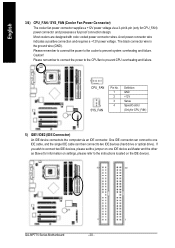
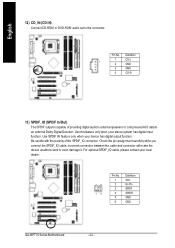
...). Please remem ber to connect the power to the cooler to the computer via a 3-pin/4-pin (only for information on the IDE device). 40 39 2 1 GA-8IP775 Series Motherboard - 20 - Most coolers are designed with color-coded power connector wires. Caution! A red power connector wire indicates a positive connection and requires a +12V power voltage...
...). Please remem ber to connect the power to the cooler to the computer via a 3-pin/4-pin (only for information on the IDE device). 40 39 2 1 GA-8IP775 Series Motherboard - 20 - Most coolers are designed with color-coded power connector wires. Caution! A red power connector wire indicates a positive connection and requires a +12V power voltage...

Manual
Page 22
... 2- Pin 3: NC Pin 4: Data(-) Open:Normal Operation Close: Reset Hardware System Open:Normal Operation Close:Power On/Off Pin 1: LED anode(+) Pin 2: LED cathode(-) NC GA-8IP775 Series Motherboard - 22 - Spe aker C onnector SPEAK- 20 19 Po wer Switch Me ssa ge LED/ Po we r/ Sle ep L ED SPEAK+ PWPW+ MSGMSG+ 21 Re...
... 2- Pin 3: NC Pin 4: Data(-) Open:Normal Operation Close: Reset Hardware System Open:Normal Operation Close:Power On/Off Pin 1: LED anode(+) Pin 2: LED cathode(-) NC GA-8IP775 Series Motherboard - 22 - Spe aker C onnector SPEAK- 20 19 Po wer Switch Me ssa ge LED/ Po we r/ Sle ep L ED SPEAK+ PWPW+ MSGMSG+ 21 Re...
Manual
Page 24
Use this feature only when your local dealer. 26 15 Pin No. 1 2 3 4 5 6 Definition VCC No Pin SPDIF SPDIFI GND GND GA-8IP775 Series Motherboard - 24 - For optional SPDIF_IO cable, please contact your stereo system has digital input function. Be careful with the polarity of providing digital audio to external ...
Use this feature only when your local dealer. 26 15 Pin No. 1 2 3 4 5 6 Definition VCC No Pin SPDIF SPDIFI GND GND GA-8IP775 Series Motherboard - 24 - For optional SPDIF_IO cable, please contact your stereo system has digital input function. Be careful with the polarity of providing digital audio to external ...
Manual
Page 26
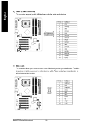
... your nearest dealer for optional external device cable. 10 9 2 1 Pin No. 1 2 3 4 5 6 7 8 9 10 Definition SMBCLK VCC SMBDATA GPIO GND GND No Pin NC +12V +12V GA-8IP775 Series Motherboard - 26 - Definition 1 VCC 2 GRX1_R 3 GND 2 16 4 GPSA2 5 VCC 1 15 6 GPX2_R 7 GPY2_R 8 MSI_R 9 GPSA1 10 GND 11 GPY1_R 12 VCC 13 GPSB1 14 MSO_R 15 GPSB2...
... your nearest dealer for optional external device cable. 10 9 2 1 Pin No. 1 2 3 4 5 6 7 8 9 10 Definition SMBCLK VCC SMBDATA GPIO GND GND No Pin NC +12V +12V GA-8IP775 Series Motherboard - 26 - Definition 1 VCC 2 GRX1_R 3 GND 2 16 4 GPSA2 5 VCC 1 15 6 GPX2_R 7 GPY2_R 8 MSI_R 9 GPSA1 10 GND 11 GPY1_R 12 VCC 13 GPSB1 14 MSO_R 15 GPSB2...

Manual
Page 28
GA-8IP775 Series Motherboard - 28 - Replace only with the same or equivalent type recommended bythe manufacturer. If you want to the manufacturer's instructions. Dispose of explosion if batteryis incorrectly replaced. English 20) BAT(Battery) Danger of used batteries according to erase CM OS... 1.Turn OFF the computer and unplug the power cord. 2.Remove the battery, wait for 30 second. 3.Re-install the battery. 4.Plug the power cord and turn ON the computer.
GA-8IP775 Series Motherboard - 28 - Replace only with the same or equivalent type recommended bythe manufacturer. If you want to the manufacturer's instructions. Dispose of explosion if batteryis incorrectly replaced. English 20) BAT(Battery) Danger of used batteries according to erase CM OS... 1.Turn OFF the computer and unplug the power cord. 2.Remove the battery, wait for 30 second. 3.Re-install the battery. 4.Plug the power cord and turn ON the computer.
Manual
Page 29
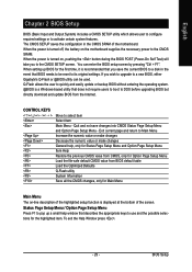
... KEYS Enter> Move to activate certain system features. BIOS Setup When the power is a Windows-based utility that BIOS needs to a new BIOS, either Gigabyte's Q-Flash or @BIOS utility can enter the BIOS setup screen by pressing "Ctrl + F1". You can be reset to a disk in the CMOS SRAM... Menu Press F1 to the CMOS SRAM. When the power is displayed at the bottom of the highlighted setup function is turned on the motherboard supplies the necessary power to pop up BIOS for the first time, it is recommended that describes the appropriate keys to Main Menu Increase...
... KEYS Enter> Move to activate certain system features. BIOS Setup When the power is a Windows-based utility that BIOS needs to a new BIOS, either Gigabyte's Q-Flash or @BIOS utility can enter the BIOS setup screen by pressing "Ctrl + F1". You can be reset to a disk in the CMOS SRAM... Menu Press F1 to the CMOS SRAM. When the power is displayed at the bottom of the highlighted setup function is turned on the motherboard supplies the necessary power to pop up BIOS for the first time, it is recommended that describes the appropriate keys to Main Menu Increase...
Manual
Page 30
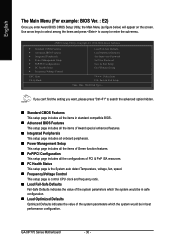
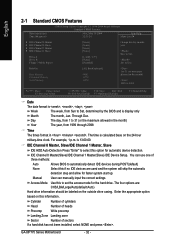
English The Main Menu (For example: BIOS Ver. : E2) Once you want, please press "Ctrl+F1" to accept or enter the sub-menu. GA-8IP775 Series Motherboard - 30 - Use arrow keys to select among the items and press to search the advanced option hidden. „ Standard CMOS Features This setup page includes ...
English The Main Menu (For example: BIOS Ver. : E2) Once you want, please press "Ctrl+F1" to accept or enter the sub-menu. GA-8IP775 Series Motherboard - 30 - Use arrow keys to select among the items and press to search the advanced option hidden. „ Standard CMOS Features This setup page includes ...
Manual
Page 32
... should be labeled on the outside drive casing. User can use one of sectors If a hard disk has not been installed, select NONE and press . GA-8IP775 Series Motherboard - 32 - Holt On Base Memory Extended Memory Total Memory [All, But Keyboard] 640K 127M 128M 1 to 2098 KLJI: Move Enter: Select F5: Previous Values...
... should be labeled on the outside drive casing. User can use one of sectors If a hard disk has not been installed, select NONE and press . GA-8IP775 Series Motherboard - 32 - Holt On Base Memory Extended Memory Total Memory [All, But Keyboard] 640K 127M 128M 1 to 2098 KLJI: Move Enter: Select F5: Previous Values...
Manual
Page 33
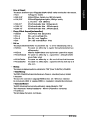
...detected during the POST. Halt on The category determines whether the computer will stop for systems with 640K or more memory installed on the motherboard. All, But Keyboard The system boot will not stop if an error is typically 512K for systems with 512K memory installed on the... motherboard, or 640K for a keyboard or disk error; This is Enabled). 720K, 3.5" 3.5 inch double-sided drive; 720K byte capacity 1.44M, 3.5" 3.5 inch double-sided drive; 1.44M...
...detected during the POST. Halt on The category determines whether the computer will stop for systems with 640K or more memory installed on the motherboard. All, But Keyboard The system boot will not stop if an error is typically 512K for systems with 512K memory installed on the... motherboard, or 640K for a keyboard or disk error; This is Enabled). 720K, 3.5" 3.5 inch double-sided drive; 720K byte capacity 1.44M, 3.5" 3.5 inch double-sided drive; 1.44M...


