Manual
Page 2
"*" Skip this step if you do not want to create RAID array on the motherboard. (To ensure that is recommended that you do not want to create RAID with identical model and capacity). If you use two hard drives with ...the GigaRAID controller, you may prepare only one hard drive. (b) An empty formatted floppy disk. (c) Windows XP/2000 setup disk. (d) Driver CD for your motherboard. (1) Installing IDE hard drive(s) in your IDE CD-ROM drive can work properly, please connect it is controlled by the GigaRAID controller on the IDE...
"*" Skip this step if you do not want to create RAID array on the motherboard. (To ensure that is recommended that you do not want to create RAID with identical model and capacity). If you use two hard drives with ...the GigaRAID controller, you may prepare only one hard drive. (b) An empty formatted floppy disk. (c) Windows XP/2000 setup disk. (d) Driver CD for your motherboard. (1) Installing IDE hard drive(s) in your IDE CD-ROM drive can work properly, please connect it is controlled by the GigaRAID controller on the IDE...
Manual
Page 3
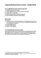
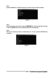
Step 1: Turn on the motherboard you have to make sure whether the GigaRAID controller are configured correctly in system BIOS Setup and set BIOS boot sequence for your computer and ... Setup during POST (Power-On Self Test). IDE RAID Drives Configuration (GigaRAID) The actual BIOS Setup menu options you will see shall depend on your motherboard. (2) Configuring GigaRAID controller mode and boot sequence in BIOS Setup You have and the BIOS version . - 3 - If you do not want to create RAID, assure...
Step 1: Turn on the motherboard you have to make sure whether the GigaRAID controller are configured correctly in system BIOS Setup and set BIOS boot sequence for your computer and ... Setup during POST (Power-On Self Test). IDE RAID Drives Configuration (GigaRAID) The actual BIOS Setup menu options you will see shall depend on your motherboard. (2) Configuring GigaRAID controller mode and boot sequence in BIOS Setup You have and the BIOS version . - 3 - If you do not want to create RAID, assure...
Manual
Page 14
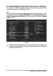
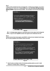
...hard drive may not be recognized during OS installation. Figure 16 Step 3: Go to a floppydisk. Step 1: Find an available system and insert the motherboard driver CD into the CD-ROM drive. Step 2: Go to install required driver for an executable program named MENU.exe (Figure 17). The installation ... will appear automatically. Ác (4) Making a IDE RAID controller driver disk Åé To install Windows 2000/XP onto a hard drive on your motherboard during the Windows setup process. ¤å First of all, you need to copy the driver for the IDE RAID controller from the...
...hard drive may not be recognized during OS installation. Figure 16 Step 3: Go to a floppydisk. Step 1: Find an available system and insert the motherboard driver CD into the CD-ROM drive. Step 2: Go to install required driver for an executable program named MENU.exe (Figure 17). The installation ... will appear automatically. Ác (4) Making a IDE RAID controller driver disk Åé To install Windows 2000/XP onto a hard drive on your motherboard during the Windows setup process. ¤å First of all, you need to copy the driver for the IDE RAID controller from the...
Manual
Page 15
Press 2 to Figure 18 below will take about one minute to copy the GigaRAID driver from the motherboard driver CD to exit when the procedure is complete (Figure 19). Figure 19 - 15 - An MS-DOS prompt screen similar to select the 2)GIGARAID item. You have copied the IDE RAID driver sucessfully. Then it will appear. Step 5: Press 0 to the floppy disk. Step 3: Double-click MENU.exe. Figure 18 Step 4: Insert an empty floppy disk. IDE RAID Drives Configuration (GigaRAID)
Press 2 to Figure 18 below will take about one minute to copy the GigaRAID driver from the motherboard driver CD to exit when the procedure is complete (Figure 19). Figure 19 - 15 - An MS-DOS prompt screen similar to select the 2)GIGARAID item. You have copied the IDE RAID driver sucessfully. Then it will appear. Step 5: Press 0 to the floppy disk. Step 3: Double-click MENU.exe. Figure 18 Step 4: Insert an empty floppy disk. IDE RAID Drives Configuration (GigaRAID)
Manual
Page 17
... from the floppy disk. The driver installation will be found, please check the floppy disk or copy the correct GigaRAID controller driver again from the motherboard driver CD. Figure 23 "*" Select the driver according to which of the following operating systems you want to select ITE IT8212 ATA RAID Controller (Windows...
... from the floppy disk. The driver installation will be found, please check the floppy disk or copy the correct GigaRAID controller driver again from the motherboard driver CD. Figure 23 "*" Select the driver according to which of the following operating systems you want to select ITE IT8212 ATA RAID Controller (Windows...
Manual
Page 72
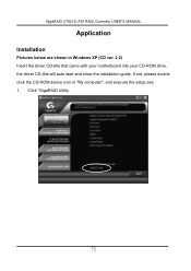
Click "GigaRAID Utility. 72 If not, please double click the CD-ROM device icon in Windows XP (CD ver. 2.2) Insert the driver CD-title that came with your motherboard into your CD-ROM drive, the driver CD-title will auto start and show the installation guide. GigaRAID (IT8212) ATA RAID Controller USER'S MANUAL Application Installation Pictures below are shown in "My computer", and execute the setup.exe. 1.
Click "GigaRAID Utility. 72 If not, please double click the CD-ROM device icon in Windows XP (CD ver. 2.2) Insert the driver CD-title that came with your motherboard into your CD-ROM drive, the driver CD-title will auto start and show the installation guide. GigaRAID (IT8212) ATA RAID Controller USER'S MANUAL Application Installation Pictures below are shown in "My computer", and execute the setup.exe. 1.
Manual
Page 1
GA-8I955X Royal/ GA-8I955X Pro Intel® Pentium® Processor Extreme Edition Intel® Pentium® D / Pentium® 4 LGA775 Processor Motherboard User's Manual Rev. 1105 12ME-8I955XRO-1105 * The WEEE marking on the product indicates this product must not be disposed of with user's other household waste and must be handed over to a designated collection point for the recycling of waste electrical and electronic equipment!! * The WEEE marking applies only in European Union's member states.
GA-8I955X Royal/ GA-8I955X Pro Intel® Pentium® Processor Extreme Edition Intel® Pentium® D / Pentium® 4 LGA775 Processor Motherboard User's Manual Rev. 1105 12ME-8I955XRO-1105 * The WEEE marking on the product indicates this product must not be disposed of with user's other household waste and must be handed over to a designated collection point for the recycling of waste electrical and electronic equipment!! * The WEEE marking applies only in European Union's member states.

Manual
Page 2
Motherboard GA-8I955X Royal April 18, 2005 Motherboard GA-8I955X Royal April 18, 2005
Motherboard GA-8I955X Royal April 18, 2005 Motherboard GA-8I955X Royal April 18, 2005

Manual
Page 3
Motherboard GA-8I955X Pro May 6, 2005 Motherboard GA-8I955X Pro May 6, 2005
Motherboard GA-8I955X Pro May 6, 2005 Motherboard GA-8I955X Pro May 6, 2005

Manual
Page 5
Table of Contents GA-8I955X Royal/GA-8I955X Pro Motherboard Layout 7 Block Diagram ...8 Chapter 1 Hardware Installation 9 1-1 Considerations Prior to Installation 9 1-2 Feature Summary 10 1-3 Installation of the CPU and Heatsink 12 1-3-1 ... Dual Power System 17 1-8 I/O Back Panel Introduction 18 1-9 Connectors Introduction 19 Chapter 2 BIOS Setup 29 The Main Menu (For example: BIOS Ver. : GA-8I955X Royal F6c 30 2-1 Standard CMOS Features 32 2-2 Advanced BIOS Features 34 2-3 IntegratedPeripherals 36 2-4 Power Management Setup 39 2-5 PnP/PCI Configurations 40 2-6 PC Health Status...
Table of Contents GA-8I955X Royal/GA-8I955X Pro Motherboard Layout 7 Block Diagram ...8 Chapter 1 Hardware Installation 9 1-1 Considerations Prior to Installation 9 1-2 Feature Summary 10 1-3 Installation of the CPU and Heatsink 12 1-3-1 ... Dual Power System 17 1-8 I/O Back Panel Introduction 18 1-9 Connectors Introduction 19 Chapter 2 BIOS Setup 29 The Main Menu (For example: BIOS Ver. : GA-8I955X Royal F6c 30 2-1 Standard CMOS Features 32 2-2 Advanced BIOS Features 34 2-3 IntegratedPeripherals 36 2-4 Power Management Setup 39 2-5 PnP/PCI Configurations 40 2-6 PC Health Status...
Manual
Page 7
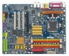
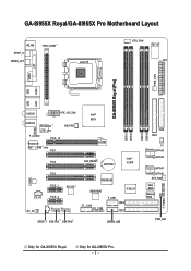
GA-8I955X Royal/GA-8I955X Pro Motherboard Layout KB_MS SPDIF_O SPDIFO_OPT VRM_CONN LGA775 CPU_FAN IT8712F ATX COMA LPT GA-8I955X Royal (Pro) PWR_FAN LAN1 LAN2 USB USB AUDIO1 ATX_12V_2X4 AUDIO2 Broadcom 5751 phy F_AUDIO PCIE_16 Broadcom 5751 / 5789 phy PCI1 NB_FAN PCI2 Intel® 955X CLR_CMOS ... IDE3 SPDIF_I ESATAII1 ESATAII0 GREEN_USB DDRII1 DDRII2 DDRII3 DDRII4 FDD IDE1 CI SATAII3 SATAII2 SATAII1 SATAII0 SYS_FAN Main BIOS Backup BIOS PWR_LED F_PANEL Only for GA-8I955X Pro. - 7 - Only for GA-8I955X Royal.
GA-8I955X Royal/GA-8I955X Pro Motherboard Layout KB_MS SPDIF_O SPDIFO_OPT VRM_CONN LGA775 CPU_FAN IT8712F ATX COMA LPT GA-8I955X Royal (Pro) PWR_FAN LAN1 LAN2 USB USB AUDIO1 ATX_12V_2X4 AUDIO2 Broadcom 5751 phy F_AUDIO PCIE_16 Broadcom 5751 / 5789 phy PCI1 NB_FAN PCI2 Intel® 955X CLR_CMOS ... IDE3 SPDIF_I ESATAII1 ESATAII0 GREEN_USB DDRII1 DDRII2 DDRII3 DDRII4 FDD IDE1 CI SATAII3 SATAII2 SATAII1 SATAII0 SYS_FAN Main BIOS Backup BIOS PWR_LED F_PANEL Only for GA-8I955X Pro. - 7 - Only for GA-8I955X Royal.
Manual
Page 8
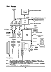
Only for GA-8I955X Royal. Only for GA-8I955X Pro. - 8 - Block Diagram PCI-ECLK (100MHz) LGA775 Processor CPUCLK+/-(266/200/133MHz) PCI Express x16 LAN LAN1 LAN2 RJ45 RJ45 RJ45 Broadcom Broadcom Broadcom 5789 ... SPDIF Out 3 PCI PCICLK(33MHz) (Note 1) DDR II memory can be overclocked to GIGABYTE's website for more information about the supported DDR II memory modules for this feature. (Note 2) To use a DDR II 667 memory module on the motherboard, you must be used with a 1066MHz FSB processor) through overclocking in BIOS. Go...
Only for GA-8I955X Royal. Only for GA-8I955X Pro. - 8 - Block Diagram PCI-ECLK (100MHz) LGA775 Processor CPUCLK+/-(266/200/133MHz) PCI Express x16 LAN LAN1 LAN2 RJ45 RJ45 RJ45 Broadcom Broadcom Broadcom 5789 ... SPDIF Out 3 PCI PCICLK(33MHz) (Note 1) DDR II memory can be overclocked to GIGABYTE's website for more information about the supported DDR II memory modules for this feature. (Note 2) To use a DDR II 667 memory module on the motherboard, you must be used with a 1066MHz FSB processor) through overclocking in BIOS. Go...
Manual
Page 9
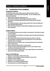
... any metal leads or connectors. 3. Please make sure there are required for warranty validation. 2. Please do not remove the stickers on the motherboard. Damage due to be an unofficial Gigabyte product. - 9 - Damage due to use exceeding the permitted parameters. 6. Damage due to use of uncertified components. 5. These stickers are no leftover screws...
... any metal leads or connectors. 3. Please make sure there are required for warranty validation. 2. Please do not remove the stickers on the motherboard. Damage due to be an unofficial Gigabyte product. - 9 - Damage due to use exceeding the permitted parameters. 6. Damage due to use of uncertified components. 5. These stickers are no leftover screws...

Manual
Page 10
...memory is reserved for system usage and therefore the actual memory size is less than the stated amount. Only for GA-8I955X Royal. MIC ; Only for GA-8I955X Pro. GA-8I955X Royal/GA-8I955X Pro Motherboard - 10 - Go to 8GB memory)(Note 2) Supports dual channel DDR II 888(Note 3)/ 667 (Note 4)/... 1 FDD connection, allows connection of 2 IDE devices - Side Speaker Out connection (Note 1) For further CPU support information, please go to GIGABYTE's website. (Note 2) Due to standard PC architecture, a certain amount of memory size will instead be shown as 7.xxGB memory during system ...
...memory is reserved for system usage and therefore the actual memory size is less than the stated amount. Only for GA-8I955X Royal. MIC ; Only for GA-8I955X Pro. GA-8I955X Royal/GA-8I955X Pro Motherboard - 10 - Go to 8GB memory)(Note 2) Supports dual channel DDR II 888(Note 3)/ 667 (Note 4)/... 1 FDD connection, allows connection of 2 IDE devices - Side Speaker Out connection (Note 1) For further CPU support information, please go to GIGABYTE's website. (Note 2) Due to standard PC architecture, a certain amount of memory size will instead be shown as 7.xxGB memory during system ...

Manual
Page 11
supports ATAPI mode for GA-8I955X Royal. supports IDE bus master operation - displays status and error checking messages during boot-up to 300 MB/s - supports data striping (RAID 0), mirroring (RAID 1), striping + ...6) EasyTune 5 functions may vary depending on the Win 2000/XP/Server 2003 operating systems Use of up - mirroring supports automatic background rebuilds - supported on different motherboards. supports ATA133/RAID mode switch by BIOS - supports a maximum of 4 SATA 3Gb/s connections - features LBA and Extended Interrupt 13 drive translation in controller onboard...
supports ATAPI mode for GA-8I955X Royal. supports IDE bus master operation - displays status and error checking messages during boot-up to 300 MB/s - supports data striping (RAID 0), mirroring (RAID 1), striping + ...6) EasyTune 5 functions may vary depending on the Win 2000/XP/Server 2003 operating systems Use of up - mirroring supports automatic background rebuilds - supported on different motherboards. supports ATA133/RAID mode switch by BIOS - supports a maximum of 4 SATA 3Gb/s connections - features LBA and Extended Interrupt 13 drive translation in controller onboard...
Manual
Page 12
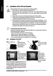
... that supports HT Technology and has it enabled - OS: An operation system that might cause damage to the CPU during installation.) GA-8I955X Royal/GA-8I955X Pro Motherboard - 12 - Avoid twisting or bending motions that has optimizations for HT Technology 1-3-1 Installation of the CPU Metal Lever Fig. 1...on the CPU socket to system use, otherwise overheating and permanent damage of the CPU may occur. 5. BIOS: A BIOS that the motherboard supports the CPU. 2. CPU: An Intel® Pentium 4 Processor with the processor specifications. Fig. 3 Notice the small gold colored...
... that supports HT Technology and has it enabled - OS: An operation system that might cause damage to the CPU during installation.) GA-8I955X Royal/GA-8I955X Pro Motherboard - 12 - Avoid twisting or bending motions that has optimizations for HT Technology 1-3-1 Installation of the CPU Metal Lever Fig. 1...on the CPU socket to system use, otherwise overheating and permanent damage of the CPU may occur. 5. BIOS: A BIOS that the motherboard supports the CPU. 2. CPU: An Intel® Pentium 4 Processor with the processor specifications. Fig. 3 Notice the small gold colored...

Manual
Page 13
...to the heatsink installation section of the user manual) Fig. 5 Please check the back of motherboard after installing. Fig. 6 Finally, please attach the power connector of the heatsink to the pin hole on the motherboard.Pressing down the push pins diagonally. English 1-3-2 Installation of the Heatsink Male Push Pin The... top of Female Push Pin Female Push Pin Fig.1 Please apply an even layer of heatsink paste on the motherboard. Fig. 2 (Turning the push pin along the direction of arrow is to remove the heatsink, on the contrary, is to install.) Please ...
...to the heatsink installation section of the user manual) Fig. 5 Please check the back of motherboard after installing. Fig. 6 Finally, please attach the power connector of the heatsink to the pin hole on the motherboard.Pressing down the push pins diagonally. English 1-3-2 Installation of the Heatsink Male Push Pin The... top of Female Push Pin Female Push Pin Fig.1 Please apply an even layer of heatsink paste on the motherboard. Fig. 2 (Turning the push pin along the direction of arrow is to remove the heatsink, on the contrary, is to install.) Please ...
Manual
Page 14
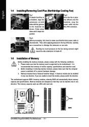
...modules are unable to the top of Memory Before installing the memory modules, please comply with the grooves in one direction. GA-8I955X Royal/GA-8I955X Pro Motherboard - 14 - Exerting too much pressure on both sides with the following conditions: 1. Then, while applying pressure to ...insert the module, please switch the direction. The memory capacity used . 2. Memory modules have a foolproof insertion design. The motherboard supports DDR II memory modules, whereby BIOS will automatically detect memory capacity and specifications. Fig.2 Once the fan is properly affixed onto...
...modules are unable to the top of Memory Before installing the memory modules, please comply with the grooves in one direction. GA-8I955X Royal/GA-8I955X Pro Motherboard - 14 - Exerting too much pressure on both sides with the following conditions: 1. Then, while applying pressure to ...insert the module, please switch the direction. The memory capacity used . 2. Memory modules have a foolproof insertion design. The motherboard supports DDR II memory modules, whereby BIOS will automatically detect memory capacity and specifications. Fig.2 Once the fan is properly affixed onto...

Manual
Page 16
...expansion card: Please align the VGA card to the onboard PCI Express x 16 slot and press firmly down on the card are indeed seated in motherboard. 4. English 1-6 Installation of Expansion Cards You can install your computer's chassis cover. 7. Replace your expansion card by the latch at the ... card, please gently press the latch as the picture to the left shows to secure the slot bracket of expansion card from BIOS. 8. GA-8I955X Royal/GA-8I955X Pro Motherboard - 16 - Be sure the metal contacts on the slot. Replace the screw to release the card. Remove your VGA card is locked...
...expansion card: Please align the VGA card to the onboard PCI Express x 16 slot and press firmly down on the card are indeed seated in motherboard. 4. English 1-6 Installation of Expansion Cards You can install your computer's chassis cover. 7. Replace your expansion card by the latch at the ... card, please gently press the latch as the picture to the left shows to secure the slot bracket of expansion card from BIOS. 8. GA-8I955X Royal/GA-8I955X Pro Motherboard - 16 - Be sure the metal contacts on the slot. Replace the screw to release the card. Remove your VGA card is locked...

Manual
Page 17
... can only fit in a Dual Power System: Parallel Mode-U-Plus DPS and motherboard CPU power can work in one direction. 2. Designed to withstand varying current levels and changes, the U-Plus DPS provides an immensely durable and stable power circuit to the CPU for GA-8I955X Royal. - 17 - Hardware Installation Only for solid system stability.
... can only fit in a Dual Power System: Parallel Mode-U-Plus DPS and motherboard CPU power can work in one direction. 2. Designed to withstand varying current levels and changes, the U-Plus DPS provides an immensely durable and stable power circuit to the CPU for GA-8I955X Royal. - 17 - Hardware Installation Only for solid system stability.


