Manual
Page 2
"*" Skip this step if you do not want to create RAID array on the motherboard. (To ensure that your IDE CD-ROM drive can work properly, please connect it to the IDE port that is controlled by the Southbridge, not ...the GigaRAID controller). If you may prepare only one hard drive. (b) An empty formatted floppy disk. (c) Windows XP/2000 setup disk. (d) Driver CD for your motherboard. (1) Installing IDE hard drive(s) in your system Attach one end of the IDE cable to the rear of the IDE hard drive and the other...
"*" Skip this step if you do not want to create RAID array on the motherboard. (To ensure that your IDE CD-ROM drive can work properly, please connect it to the IDE port that is controlled by the Southbridge, not ...the GigaRAID controller). If you may prepare only one hard drive. (b) An empty formatted floppy disk. (c) Windows XP/2000 setup disk. (d) Driver CD for your motherboard. (1) Installing IDE hard drive(s) in your system Attach one end of the IDE cable to the rear of the IDE hard drive and the other...
Manual
Page 3
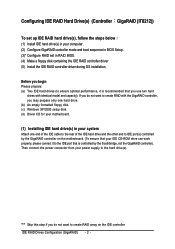
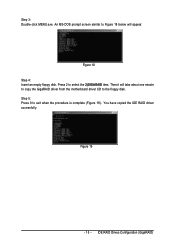
... the IDE RAID hard drive(s). The actual BIOS Setup menu options you will see shall depend on your motherboard. If you have to ATA. IDE RAID Drives Configuration (GigaRAID) Step 1: Turn on the motherboard you want to create RAID, set to Enabled and GigaRAID Function to enter BIOS Setup during POST (Power...
... the IDE RAID hard drive(s). The actual BIOS Setup menu options you will see shall depend on your motherboard. If you have to ATA. IDE RAID Drives Configuration (GigaRAID) Step 1: Turn on the motherboard you want to create RAID, set to Enabled and GigaRAID Function to enter BIOS Setup during POST (Power...
Manual
Page 14
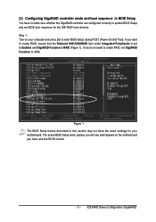
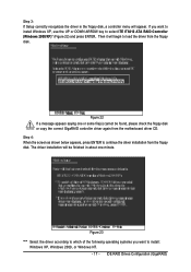
...; To install Windows 2000/XP onto a hard drive on the GigaRAID controller successfully, you need to install required driver for the GigaRAID controller on your motherboard during the Windows setup process. ¤å First of all, you need to copy the driver for the IDE RAID controller from the...
...; To install Windows 2000/XP onto a hard drive on the GigaRAID controller successfully, you need to install required driver for the GigaRAID controller on your motherboard during the Windows setup process. ¤å First of all, you need to copy the driver for the IDE RAID controller from the...
Manual
Page 15
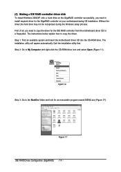
Then it will take about one minute to copy the GigaRAID driver from the motherboard driver CD to Figure 18 below will appear. You have copied the IDE RAID driver sucessfully. An MS-DOS prompt screen similar to the floppy disk. IDE RAID Drives Configuration (GigaRAID) Step 5: Press 0 to select the 2)GIGARAID item. Press 2 to exit when the procedure is complete (Figure 19). Figure 19 - 15 - Figure 18 Step 4: Insert an empty floppy disk. Step 3: Double-click MENU.exe.
Then it will take about one minute to copy the GigaRAID driver from the motherboard driver CD to Figure 18 below will appear. You have copied the IDE RAID driver sucessfully. An MS-DOS prompt screen similar to the floppy disk. IDE RAID Drives Configuration (GigaRAID) Step 5: Press 0 to select the 2)GIGARAID item. Press 2 to exit when the procedure is complete (Figure 19). Figure 19 - 15 - Figure 18 Step 4: Insert an empty floppy disk. Step 3: Double-click MENU.exe.
Manual
Page 17
..., or Windows NT. - 17 - The driver installation will be found, please check the floppy disk or copy the correct GigaRAID controller driver again from the motherboard driver CD. If you want to install Windows XP, use the UP or DOWN ARROW key to load the driver from the floppy disk. Figure...
..., or Windows NT. - 17 - The driver installation will be found, please check the floppy disk or copy the correct GigaRAID controller driver again from the motherboard driver CD. If you want to install Windows XP, use the UP or DOWN ARROW key to load the driver from the floppy disk. Figure...
Manual
Page 72
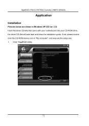
If not, please double click the CD-ROM device icon in Windows XP (CD ver. 2.2) Insert the driver CD-title that came with your motherboard into your CD-ROM drive, the driver CD-title will auto start and show the installation guide. Click "GigaRAID Utility. 72 GigaRAID (IT8212) ATA RAID Controller USER'S MANUAL Application Installation Pictures below are shown in "My computer", and execute the setup.exe. 1.
If not, please double click the CD-ROM device icon in Windows XP (CD ver. 2.2) Insert the driver CD-title that came with your motherboard into your CD-ROM drive, the driver CD-title will auto start and show the installation guide. Click "GigaRAID Utility. 72 GigaRAID (IT8212) ATA RAID Controller USER'S MANUAL Application Installation Pictures below are shown in "My computer", and execute the setup.exe. 1.
Manual
Page 1
GA-8I955X Royal/ GA-8I955X Pro Intel® Pentium® Processor Extreme Edition Intel® Pentium® D / Pentium® 4 LGA775 Processor Motherboard User's Manual Rev. 1105 12ME-8I955XRO-1105 * The WEEE marking on the product indicates this product must not be disposed of with user's other household waste and must be handed over to a designated collection point for the recycling of waste electrical and electronic equipment!! * The WEEE marking applies only in European Union's member states.
GA-8I955X Royal/ GA-8I955X Pro Intel® Pentium® Processor Extreme Edition Intel® Pentium® D / Pentium® 4 LGA775 Processor Motherboard User's Manual Rev. 1105 12ME-8I955XRO-1105 * The WEEE marking on the product indicates this product must not be disposed of with user's other household waste and must be handed over to a designated collection point for the recycling of waste electrical and electronic equipment!! * The WEEE marking applies only in European Union's member states.

Manual
Page 2
Motherboard GA-8I955X Royal April 18, 2005 Motherboard GA-8I955X Royal April 18, 2005
Motherboard GA-8I955X Royal April 18, 2005 Motherboard GA-8I955X Royal April 18, 2005

Manual
Page 3
Motherboard GA-8I955X Pro May 6, 2005 Motherboard GA-8I955X Pro May 6, 2005
Motherboard GA-8I955X Pro May 6, 2005 Motherboard GA-8I955X Pro May 6, 2005

Manual
Page 5
Table of Contents GA-8I955X Royal/GA-8I955X Pro Motherboard Layout 7 Block Diagram ...8 Chapter 1 Hardware Installation 9 1-1 Considerations Prior to Installation 9 1-2 Feature Summary 10 1-3 Installation of the CPU and Heatsink 12 1-3-1 ... Dual Power System 17 1-8 I/O Back Panel Introduction 18 1-9 Connectors Introduction 19 Chapter 2 BIOS Setup 29 The Main Menu (For example: BIOS Ver. : GA-8I955X Royal F6c 30 2-1 Standard CMOS Features 32 2-2 Advanced BIOS Features 34 2-3 IntegratedPeripherals 36 2-4 Power Management Setup 39 2-5 PnP/PCI Configurations 40 2-6 PC Health Status...
Table of Contents GA-8I955X Royal/GA-8I955X Pro Motherboard Layout 7 Block Diagram ...8 Chapter 1 Hardware Installation 9 1-1 Considerations Prior to Installation 9 1-2 Feature Summary 10 1-3 Installation of the CPU and Heatsink 12 1-3-1 ... Dual Power System 17 1-8 I/O Back Panel Introduction 18 1-9 Connectors Introduction 19 Chapter 2 BIOS Setup 29 The Main Menu (For example: BIOS Ver. : GA-8I955X Royal F6c 30 2-1 Standard CMOS Features 32 2-2 Advanced BIOS Features 34 2-3 IntegratedPeripherals 36 2-4 Power Management Setup 39 2-5 PnP/PCI Configurations 40 2-6 PC Health Status...
Manual
Page 7
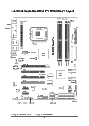
Only for GA-8I955X Royal. GA-8I955X Royal/GA-8I955X Pro Motherboard Layout KB_MS SPDIF_O SPDIFO_OPT VRM_CONN LGA775 CPU_FAN IT8712F ATX COMA LPT GA-8I955X Royal (Pro) PWR_FAN LAN1 LAN2 USB USB AUDIO1 ATX_12V_2X4 AUDIO2 Broadcom 5751 phy F_AUDIO PCIE_16 Broadcom 5751 / 5789 phy PCI1 NB_FAN PCI2 Intel® 955X CLR_CMOS ... IDE3 SPDIF_I ESATAII1 ESATAII0 GREEN_USB DDRII1 DDRII2 DDRII3 DDRII4 FDD IDE1 CI SATAII3 SATAII2 SATAII1 SATAII0 SYS_FAN Main BIOS Backup BIOS PWR_LED F_PANEL Only for GA-8I955X Pro. - 7 -
Only for GA-8I955X Royal. GA-8I955X Royal/GA-8I955X Pro Motherboard Layout KB_MS SPDIF_O SPDIFO_OPT VRM_CONN LGA775 CPU_FAN IT8712F ATX COMA LPT GA-8I955X Royal (Pro) PWR_FAN LAN1 LAN2 USB USB AUDIO1 ATX_12V_2X4 AUDIO2 Broadcom 5751 phy F_AUDIO PCIE_16 Broadcom 5751 / 5789 phy PCI1 NB_FAN PCI2 Intel® 955X CLR_CMOS ... IDE3 SPDIF_I ESATAII1 ESATAII0 GREEN_USB DDRII1 DDRII2 DDRII3 DDRII4 FDD IDE1 CI SATAII3 SATAII2 SATAII1 SATAII0 SYS_FAN Main BIOS Backup BIOS PWR_LED F_PANEL Only for GA-8I955X Pro. - 7 -
Manual
Page 8
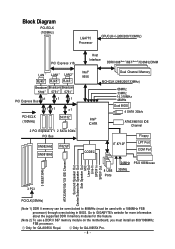
... feature. (Note 2) To use a DDR II 667 memory module on the motherboard, you must be overclocked to GIGABYTE's website for more information about the supported DDR II memory modules for GA-8I955X Royal. Go to 888MHz (must install an 800/1066MHz FSB processor. Only for GA-8I955X Pro. - 8 - Block Diagram PCI-ECLK (100MHz) LGA775 Processor CPUCLK+/-(266...
... feature. (Note 2) To use a DDR II 667 memory module on the motherboard, you must be overclocked to GIGABYTE's website for more information about the supported DDR II memory modules for GA-8I955X Royal. Go to 888MHz (must install an 800/1066MHz FSB processor. Only for GA-8I955X Pro. - 8 - Block Diagram PCI-ECLK (100MHz) LGA775 Processor CPUCLK+/-(266...
Manual
Page 9
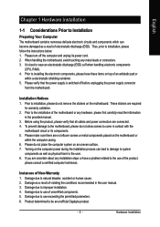
...installation, please follow the instructions below: 1. Thus, prior to be an unofficial Gigabyte product. - 9 - When handling the motherboard, avoid touching any hardware, please first carefully read the information in contact with the motherboard circuit or its power cord. 2. It is switched off the computer and ...have these items on an uneven surface. 7. Prior to use of Non-Warranty 1. Please do not remove the stickers on the motherboard. Damage as physical harm to natural disaster, accident or human cause. 2. Damage due to wear an electrostatic discharge (ESD) ...
...installation, please follow the instructions below: 1. Thus, prior to be an unofficial Gigabyte product. - 9 - When handling the motherboard, avoid touching any hardware, please first carefully read the information in contact with the motherboard circuit or its power cord. 2. It is switched off the computer and ...have these items on an uneven surface. 7. Prior to use of Non-Warranty 1. Please do not remove the stickers on the motherboard. Damage as physical harm to natural disaster, accident or human cause. 2. Damage due to wear an electrostatic discharge (ESD) ...

Manual
Page 10
... of 2 FDD devices 4 ports from ICH7R controller (SATAII0, SATAII1, SATAII2, SATAII3) - Only for GA-8I955X Pro. Only for GA-8I955X Royal. Supported on the Win 2000/XP operating systems 2 ports from Sil3132 controller (ESATAII0, ESATAII1) - Line Out (Front Speaker Out) ; GA-8I955X Royal/GA-8I955X Pro Motherboard - 10 - MIC ; Center/Subwoofer Speaker Out ; Go to 888MHz (must install an 800/1066MHz...
... of 2 FDD devices 4 ports from ICH7R controller (SATAII0, SATAII1, SATAII2, SATAII3) - Only for GA-8I955X Pro. Only for GA-8I955X Royal. Supported on the Win 2000/XP operating systems 2 ports from Sil3132 controller (ESATAII0, ESATAII1) - Line Out (Front Speaker Out) ; GA-8I955X Royal/GA-8I955X Pro Motherboard - 10 - MIC ; Center/Subwoofer Speaker Out ; Go to 888MHz (must install an 800/1066MHz...

Manual
Page 11
...or mirroring (RAID 1) or striping + mirroring (RAID 0+1) function - supports IDE bus master operation - supports a maximum of 2 SATA 3Gb/s connections - supports hot plugging function - Only for GA-8I955X Royal. supports data striping (RAID 0), mirroring (RAID 1), striping + mirroring (RAID 0+1), or RAID 5 - supports data transfer rate of licensed AWARD BIOS Supports Dual BIOS/Q-Flash/Multilanguage BIOS... rebuilds - supports ATA133/RAID mode switch by BIOS - displays status and error checking messages during boot-up to 300 MB/s - supported on different motherboards.
...or mirroring (RAID 1) or striping + mirroring (RAID 0+1) function - supports IDE bus master operation - supports a maximum of 2 SATA 3Gb/s connections - supports hot plugging function - Only for GA-8I955X Royal. supports data striping (RAID 0), mirroring (RAID 1), striping + mirroring (RAID 0+1), or RAID 5 - supports data transfer rate of licensed AWARD BIOS Supports Dual BIOS/Q-Flash/Multilanguage BIOS... rebuilds - supports ATA133/RAID mode switch by BIOS - displays status and error checking messages during boot-up to 300 MB/s - supported on different motherboards.
Manual
Page 12
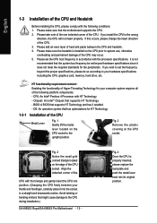
...Installation of the CPU Metal Lever Fig. 1 Gently lift the metal lever located on the CPU prior to the CPU during installation.) GA-8I955X Royal/GA-8I955X Pro Motherboard - 12 - HT functionality requirement content : Enabling the functionality of Hyper-Threading Technology for your thumb and forefinger, carefully place it...gently insert the CPU into position. (Grasping the CPU firmly between the CPU and heatsink. 4. OS: An operation system that the motherboard supports the CPU. 2. Please add an even layer of heat sink paste between your computer system requires all of the CPU socket....
...Installation of the CPU Metal Lever Fig. 1 Gently lift the metal lever located on the CPU prior to the CPU during installation.) GA-8I955X Royal/GA-8I955X Pro Motherboard - 12 - HT functionality requirement content : Enabling the functionality of Hyper-Threading Technology for your thumb and forefinger, carefully place it...gently insert the CPU into position. (Grasping the CPU firmly between the CPU and heatsink. 4. OS: An operation system that the motherboard supports the CPU. 2. Please add an even layer of heat sink paste between your computer system requires all of the CPU socket....

Manual
Page 13
... for detailed installation instructions, please refer to the CPU fan header located on the motherboard. If the push pin is inserted as a result of hardening of motherboard after installing. The heatsink may adhere to the pin hole on the motherboard.Pressing down the push pins diagonally. English 1-3-2 Installation of the Heatsink Male Push...
... for detailed installation instructions, please refer to the CPU fan header located on the motherboard. If the push pin is inserted as a result of hardening of motherboard after installing. The heatsink may adhere to the pin hole on the motherboard.Pressing down the push pins diagonally. English 1-3-2 Installation of the Heatsink Male Push...
Manual
Page 14
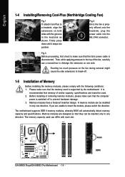
... insertion design. The memory capacity used is properly affixed onto the heatsink, plug the power cable into position. The motherboard supports DDR II memory modules, whereby BIOS will automatically detect memory capacity and specifications. Notch DDR II Then, while applying...power cable is switched off . 1-5 Installation of similar capacity, specifications and brand be inserted only in the heatsink as shown. GA-8I955X Royal/GA-8I955X Pro Motherboard - 14 - Fig.3 Before proceeding, first check to insert the module, please switch the direction. A memory module can differ...
... insertion design. The memory capacity used is properly affixed onto the heatsink, plug the power cable into position. The motherboard supports DDR II memory modules, whereby BIOS will automatically detect memory capacity and specifications. Notch DDR II Then, while applying...power cable is switched off . 1-5 Installation of similar capacity, specifications and brand be inserted only in the heatsink as shown. GA-8I955X Royal/GA-8I955X Pro Motherboard - 14 - Fig.3 Before proceeding, first check to insert the module, please switch the direction. A memory module can differ...

Manual
Page 16
.... 2. Power on the slot. Installing a PCI Express x 16 expansion card: Please align the VGA card to release the card. Remove your computer's chassis cover. 7. GA-8I955X Royal/GA-8I955X Pro Motherboard - 16 - Replace the screw to secure the slot bracket of the PCI Express x 16 slot. Install related driver from the computer. 3. Make sure your expansion...
.... 2. Power on the slot. Installing a PCI Express x 16 expansion card: Please align the VGA card to release the card. Remove your computer's chassis cover. 7. GA-8I955X Royal/GA-8I955X Pro Motherboard - 16 - Replace the screw to secure the slot bracket of the PCI Express x 16 slot. Install related driver from the computer. 3. Make sure your expansion...

Manual
Page 17
... you want to the CPU for GA-8I955X Royal. - 17 - Only for solid system stability. English 1-7 Installation of system loading. These characteristics make it down. 3. The U-Plus DPS socket (VRM_CONN) has a notch, so the U-Plus DPS can only fit in a Dual Power System: Parallel Mode-U-Plus DPS and motherboard CPU power can work simultaneously...
... you want to the CPU for GA-8I955X Royal. - 17 - Only for solid system stability. English 1-7 Installation of system loading. These characteristics make it down. 3. The U-Plus DPS socket (VRM_CONN) has a notch, so the U-Plus DPS can only fit in a Dual Power System: Parallel Mode-U-Plus DPS and motherboard CPU power can work simultaneously...


