Manual
Page 1
GA-8I925X-G Intel® Pentium® 4 LGA775 Processor Motherboard User's Manual Rev. 2003 12ME-8I925XG-2003
GA-8I925X-G Intel® Pentium® 4 LGA775 Processor Motherboard User's Manual Rev. 2003 12ME-8I925XG-2003
Manual
Page 2
Motherboard GA-8I925X-G Jul. 2, 2004 Motherboard GA-8I925X-G Jul. 2, 2004
Motherboard GA-8I925X-G Jul. 2, 2004 Motherboard GA-8I925X-G Jul. 2, 2004
Manual
Page 4
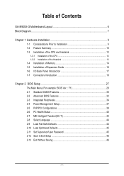
Table of Contents GA-8I925X-G Motherboard Layout 6 Block Diagram ...7 Chapter 1 Hardware Installation 9 1-1 Considerations Prior to Installation 9 1-2 Feature Summary 10 1-3 Installation of the CPU and Heatsink 12 1-3-1 Installation of the CPU ...
Table of Contents GA-8I925X-G Motherboard Layout 6 Block Diagram ...7 Chapter 1 Hardware Installation 9 1-1 Considerations Prior to Installation 9 1-2 Feature Summary 10 1-3 Installation of the CPU and Heatsink 12 1-3-1 Installation of the CPU ...
Manual
Page 6
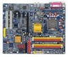
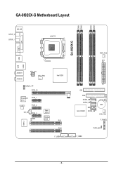
GA-8I925X-G Motherboard Layout DDRII1 DDRII2 DDRII4 DDRII5 KB_MS SPDIF_O SPDIF_I LGA775 GA-8I925X-G COM LPT USB USB LAN2 IT8712 AUDIO1 AUDIO2 ATX_12V CPU_FAN AZALIA_FP PCIE_16 Broadcom 5751 CODEC PCIE_1 PCIE_2 CD_IN PCIE_3 IR Main BIOS Backup BIOS Intel 925X PCI1 PCI2 F_USB1 PWR_FAN ATX IDE FDD SATA3_SB SATA2_SB Intel ICH6R SATA1_SB SATA0_SB BAT SYS_FAN F_PANEL PWR_LED F_USB2 CLR_CMOS - 6 -
GA-8I925X-G Motherboard Layout DDRII1 DDRII2 DDRII4 DDRII5 KB_MS SPDIF_O SPDIF_I LGA775 GA-8I925X-G COM LPT USB USB LAN2 IT8712 AUDIO1 AUDIO2 ATX_12V CPU_FAN AZALIA_FP PCIE_16 Broadcom 5751 CODEC PCIE_1 PCIE_2 CD_IN PCIE_3 IR Main BIOS Backup BIOS Intel 925X PCI1 PCI2 F_USB1 PWR_FAN ATX IDE FDD SATA3_SB SATA2_SB Intel ICH6R SATA1_SB SATA0_SB BAT SYS_FAN F_PANEL PWR_LED F_USB2 CLR_CMOS - 6 -
Manual
Page 10
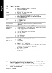
Center/Subwoofer Speaker Out ; Line Out (Front Speaker Out) ; MIC ; Surround Speaker Out (Rear Speaker Out) ; GA-8I925X-G Motherboard - 10 - Side Speaker Out connection Š SPDIF In/Out connection Š CD In connection (Note 1) Due to 4GB memory) (Note 1) Š Supports dual channel ...
Center/Subwoofer Speaker Out ; Line Out (Front Speaker Out) ; MIC ; Surround Speaker Out (Rear Speaker Out) ; GA-8I925X-G Motherboard - 10 - Side Speaker Out connection Š SPDIF In/Out connection Š CD In connection (Note 1) Due to 4GB memory) (Note 1) Š Supports dual channel ...
Manual
Page 12
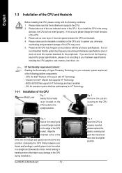
... requires all of the CPU. 3. Fig. 3 Notice the small gold colored triangle located on the CPU socket. If you wish to the CPU during installation.) GA-8I925X-G Motherboard - 12 - Please take note of the one indented corner of the CPU socket. OS: An operation system that supports HT Technology -
... requires all of the CPU. 3. Fig. 3 Notice the small gold colored triangle located on the CPU socket. If you wish to the CPU during installation.) GA-8I925X-G Motherboard - 12 - Please take note of the one indented corner of the CPU socket. OS: An operation system that supports HT Technology -
Manual
Page 14
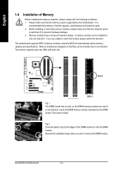
Then push it down. GA-8I925X-G Motherboard - 14 - Memory modules are unable to remove the DIMM module. Memory modules have a foolproof insertion design. The motherboard supports DDR II memory modules, whereby ...
Then push it down. GA-8I925X-G Motherboard - 14 - Memory modules are unable to remove the DIMM module. Memory modules have a foolproof insertion design. The motherboard supports DDR II memory modules, whereby ...
Manual
Page 15
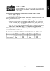
.../s(DDR400). If two DDR II memory modules are installed (same storage capacity), one or three DDR II memory modules are installed on the same channel. 3. GA-8I925X-G includes 4 DIMM sockets, and each Channel has two DIMM sockets as following: Channel A : DDR II 1, DDR II 2 Channel B : DDR II 4, DDR II ... two DDR II memory modules into the DIMMs with the same color in order to work. Hardware Installation English Dual Channel DDR II GA-8I925X-G supports the Dual Channel Technology. The following explanations due to the limitation of Memory Bus will add double up to detect all the...
.../s(DDR400). If two DDR II memory modules are installed (same storage capacity), one or three DDR II memory modules are installed on the same channel. 3. GA-8I925X-G includes 4 DIMM sockets, and each Channel has two DIMM sockets as following: Channel A : DDR II 1, DDR II 2 Channel B : DDR II 4, DDR II ... two DDR II memory modules into the DIMMs with the same color in order to work. Hardware Installation English Dual Channel DDR II GA-8I925X-G supports the Dual Channel Technology. The following explanations due to the limitation of Memory Bus will add double up to detect all the...
Manual
Page 16
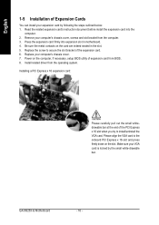
.... 4. Make sure your VGA card is locked by following the steps outlined below: 1. Press the expansion card firmly into the computer. 2. Power on the slot. GA-8I925X-G Motherboard - 16 - Replace your computer's chassis cover, screws and slot bracket from the computer. 3. English 1-5 Installation of Expansion Cards You can install your expansion card...
.... 4. Make sure your VGA card is locked by following the steps outlined below: 1. Press the expansion card firmly into the computer. 2. Power on the slot. GA-8I925X-G Motherboard - 16 - Replace your computer's chassis cover, screws and slot bracket from the computer. 3. English 1-5 Installation of Expansion Cards You can install your expansion card...
Manual
Page 18
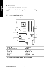
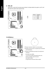
English Side Speaker Out Connect the side surround speakers to configure 2-/4-/6-/8-channel audio functioning. 1-7 Connectors Introduction 13 5 2 12 7 6 16 10 13 4 15 14 8 9 11 1) ATX_12V 9) PWR_LED 2) ATX (Power Connector) 10) BAT 3) CPU_FAN 11) F_PANEL 4) SYS_FAN 12) AZALIA_FP 5) PWR_FAN 13) CD_IN 6) FDD 14) F_USB1 / F_USB2 7) IDE 15) IR 8) SATA0_SB/SATA1_SB/SATA2_SB/SATA3_SB 16) CLR_CMOS GA-8I925X-G Motherboard - 18 - You can use audio software to this connector.
English Side Speaker Out Connect the side surround speakers to configure 2-/4-/6-/8-channel audio functioning. 1-7 Connectors Introduction 13 5 2 12 7 6 16 10 13 4 15 14 8 9 11 1) ATX_12V 9) PWR_LED 2) ATX (Power Connector) 10) BAT 3) CPU_FAN 11) F_PANEL 4) SYS_FAN 12) AZALIA_FP 5) PWR_FAN 13) CD_IN 6) FDD 14) F_USB1 / F_USB2 7) IDE 15) IR 8) SATA0_SB/SATA1_SB/SATA2_SB/SATA3_SB 16) CLR_CMOS GA-8I925X-G Motherboard - 18 - You can use audio software to this connector.
Manual
Page 20
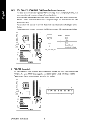
... drives supported are designed with color-coded power connector wires. Please remember to connect the power to the cooler to the pin1 position. 2 34 1 33 GA-8I925X-G Motherboard - 20 - The black connector wire is used to the FDD drive.
... drives supported are designed with color-coded power connector wires. Please remember to connect the power to the cooler to the pin1 position. 2 34 1 33 GA-8I925X-G Motherboard - 20 - The black connector wire is used to the FDD drive.
Manual
Page 22
... incorrectly replaced. If you want to the manufacturer's instructions. It will blink when the system enters suspend mode. Definition 1 MPD+ 2 MPD- 1 3 MPD- 10) BAT(Battery) GA-8I925X-G Motherboard Danger of used batteries according to erase CMOS... 1. Turn OFF the computer and unplug the power cord. 2. Remove the battery, wait for 30 second. 3.
... incorrectly replaced. If you want to the manufacturer's instructions. It will blink when the system enters suspend mode. Definition 1 MPD+ 2 MPD- 1 3 MPD- 10) BAT(Battery) GA-8I925X-G Motherboard Danger of used batteries according to erase CMOS... 1. Turn OFF the computer and unplug the power cord. 2. Remove the battery, wait for 30 second. 3.
Manual
Page 24
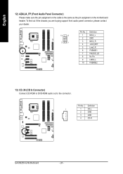
Pin No. Definition 1 1 CD-L 2 GND 3 GND 4 CD-R GA-8I925X-G Motherboard - 24 - English 12) AZALIA_FP (Front Audio Panel Connector) Please make sure the pin assigment on the cable is the same as the pin assigment on the motherboard header. To find out if the chassis you are buying support front audio panel connector, please contact your dealer. 10 9 2 1 Pin No. 1 2 3 4 5 6 7 8 9 10 Definition MIC2_L GND MIC2_R -ACZ_DET Line2_R FSENSE1 FAUOIO_JD No Pin LINE2_L FSENSE2 13) CD_IN (CD In Connector) Connect CD-ROM or DVD-ROM audio out to the connector.
Pin No. Definition 1 1 CD-L 2 GND 3 GND 4 CD-R GA-8I925X-G Motherboard - 24 - English 12) AZALIA_FP (Front Audio Panel Connector) Please make sure the pin assigment on the cable is the same as the pin assigment on the motherboard header. To find out if the chassis you are buying support front audio panel connector, please contact your dealer. 10 9 2 1 Pin No. 1 2 3 4 5 6 7 8 9 10 Definition MIC2_L GND MIC2_R -ACZ_DET Line2_R FSENSE1 FAUOIO_JD No Pin LINE2_L FSENSE2 13) CD_IN (CD In Connector) Connect CD-ROM or DVD-ROM audio out to the connector.
Manual
Page 26
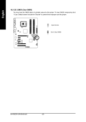
English 16) CLR_CMOS (Clear CMOS) You may clear the CMOS data to prevent from improper use this jumper. Default doesn't include the "Shunter" to its default values by this jumper. To clear CMOS, temporarily short 1-2 pin. Open: Normal 1 Short: Clear CMOS 1 GA-8I925X-G Motherboard - 26 -
English 16) CLR_CMOS (Clear CMOS) You may clear the CMOS data to prevent from improper use this jumper. Default doesn't include the "Shunter" to its default values by this jumper. To clear CMOS, temporarily short 1-2 pin. Open: Normal 1 Short: Clear CMOS 1 GA-8I925X-G Motherboard - 26 -
Manual
Page 28
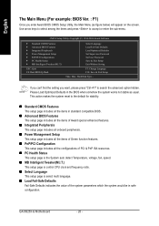
Please Load Optimized Defaults in the BIOS when somehow the system works not stable as figure below) will appear on the screen. GA-8I925X-G Motherboard - 28 - English The Main Menu (For example: BIOS Ver. : F1) Once you want, please press "Ctrl+F1" to search the advanced option hidden. Use ...
Please Load Optimized Defaults in the BIOS when somehow the system works not stable as figure below) will appear on the screen. GA-8I925X-G Motherboard - 28 - English The Main Menu (For example: BIOS Ver. : F1) Once you want, please press "Ctrl+F1" to search the advanced option hidden. Use ...
Manual
Page 30
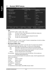
... heads Precomp Write precomp Landing Zone Landing zone Sector Number of three methods: Auto Allows BIOS to set the access mode for automatic device detection. GA-8I925X-G Motherboard - 30 - Jan. Week Month The week, from 1999 through 2098 Time The times format in the month) 1999 to select this option for the...
... heads Precomp Write precomp Landing Zone Landing zone Sector Number of three methods: Auto Allows BIOS to set the access mode for automatic device detection. GA-8I925X-G Motherboard - 30 - Jan. Week Month The week, from 1999 through 2098 Time The times format in the month) 1999 to select this option for the...

Manual
Page 32
... is not entered at the prompt. (Default value) The system will not boot and will detect automatically and show up , or to exit this menu. GA-8I925X-G Motherboard - 32 - First / Second / Third Boot Device Floppy Select your boot device priority by ZIP. USB-FDD Select your boot device priority by USB-CDROM...
... is not entered at the prompt. (Default value) The system will not boot and will detect automatically and show up , or to exit this menu. GA-8I925X-G Motherboard - 32 - First / Second / Third Boot Device Floppy Select your boot device priority by ZIP. USB-FDD Select your boot device priority by USB-CDROM...
Manual
Page 34
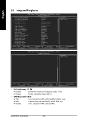
... Help F7: Optimized Defaults On-Chip Primary PCI IDE Enabled Enable onboard 1st channel IDE port. (Default value) Disabled Disable onboard 1st channel IDE port. GA-8I925X-G Motherboard - 34 - Disabled Select onboard Seria ATA function as RAID. (Default value) AHCI Support hotplug function under OS. WinXP, 2000 only. SATA RAID / AHCI Mode...
... Help F7: Optimized Defaults On-Chip Primary PCI IDE Enabled Enable onboard 1st channel IDE port. (Default value) Disabled Disable onboard 1st channel IDE port. GA-8I925X-G Motherboard - 34 - Disabled Select onboard Seria ATA function as RAID. (Default value) AHCI Support hotplug function under OS. WinXP, 2000 only. SATA RAID / AHCI Mode...
Manual
Page 36
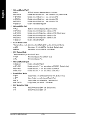
... This feature allows you to determine which Infra Red(IR) function of Onboard I /O chip UART to 1. ECP+EPP Using Parallel port as ECP & EPP mode. GA-8I925X-G Motherboard - 36 -
... This feature allows you to determine which Infra Red(IR) function of Onboard I /O chip UART to 1. ECP+EPP Using Parallel port as ECP & EPP mode. GA-8I925X-G Motherboard - 36 -
Manual
Page 38
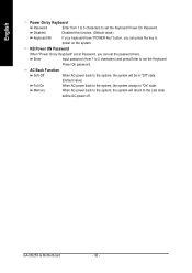
.... (Default value) Keyboard 98 If your keyboard have "POWER Key" button, you can press the key to the system, the system always in "On" state. GA-8I925X-G Motherboard - 38 -
.... (Default value) Keyboard 98 If your keyboard have "POWER Key" button, you can press the key to the system, the system always in "On" state. GA-8I925X-G Motherboard - 38 -

