
Manual
Page 4
... the CPU 12 1-3-2 Installation of the Heatsink 13 1-4 Installation of Memory 14 1-5 Installation of Expansion Cards 16 1-5-1 What is G.E.A.R 17 1-5-2 Graphics Card Support List 17 1-6 I/O Back Panel Introduction 20 1-7 Connectors Introduction 21 Chapter 2 BIOS Setup 33 The Main Menu ...34 (For example: GA-8I915ME-GV / BIOS Ver.: F2 34 2-1 Standard CMOS Features 36 2-2 Advanced BIOS Features 38 2-3 IntegratedPeripherals 40 2-4 Power Management Setup 42 2-5 PnP/PCI Configurations 44 2-6 PC Health Status 44 2-7 Frequency/Voltage Control 46 2-8 Load Fail-Safe Defaults 47 2-9 Load...
... the CPU 12 1-3-2 Installation of the Heatsink 13 1-4 Installation of Memory 14 1-5 Installation of Expansion Cards 16 1-5-1 What is G.E.A.R 17 1-5-2 Graphics Card Support List 17 1-6 I/O Back Panel Introduction 20 1-7 Connectors Introduction 21 Chapter 2 BIOS Setup 33 The Main Menu ...34 (For example: GA-8I915ME-GV / BIOS Ver.: F2 34 2-1 Standard CMOS Features 36 2-2 Advanced BIOS Features 38 2-3 IntegratedPeripherals 40 2-4 Power Management Setup 42 2-5 PnP/PCI Configurations 44 2-6 PC Health Status 44 2-7 Frequency/Voltage Control 46 2-8 Load Fail-Safe Defaults 47 2-9 Load...
Manual
Page 10
... cable) Š 1 front audio connector Š 1 PS/2 keyboard port Š 1 PS/2 mouse port Š Onboard RTL8100C chip (10/100 Mbit) Onboard Audio I/O Control Š Onboard RTL8110S chip (10/100/1000 Mbit) Š 1 RJ 45 port Š Supported on the Win 2000/XP operating systems Š 2 DDR DIMM memory slots (supports up to 4GB memory) (Note 1) Š Supports dual channel DDR400/333 DIMM Š Supports 2.5V DDR DIMM Š 1 PCI Express x 16 slot (Note 2) Š 1 G.E.A.R. Only for GA-8I915ME-GV. GA-8I915ME Series Motherboard...
... cable) Š 1 front audio connector Š 1 PS/2 keyboard port Š 1 PS/2 mouse port Š Onboard RTL8100C chip (10/100 Mbit) Onboard Audio I/O Control Š Onboard RTL8110S chip (10/100/1000 Mbit) Š 1 RJ 45 port Š Supported on the Win 2000/XP operating systems Š 2 DDR DIMM memory slots (supports up to 4GB memory) (Note 1) Š Supports dual channel DDR400/333 DIMM Š Supports 2.5V DDR DIMM Š 1 PCI Express x 16 slot (Note 2) Š 1 G.E.A.R. Only for GA-8I915ME-GV. GA-8I915ME Series Motherboard...
Manual
Page 24
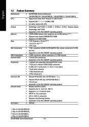
... GA-8I915ME Series Motherboard - 24 - Please refer to the BIOS setting for information on settings, please refer to the instructions located on the IDE device). 40 39 2 1 7) SATA0/SATA2 (Serial ATA Connector, Controlled by ICH6) Serial ATA can then connect to work properly. One IDE connector can connect to one IDE device as Master and the other as Slave (for the Serial ATA and install the proper driver in order to two IDE devices (hard drive or optical drive). If...
... GA-8I915ME Series Motherboard - 24 - Please refer to the BIOS setting for information on settings, please refer to the instructions located on the IDE device). 40 39 2 1 7) SATA0/SATA2 (Serial ATA Connector, Controlled by ICH6) Serial ATA can then connect to work properly. One IDE connector can connect to one IDE device as Master and the other as Slave (for the Serial ATA and install the proper driver in order to two IDE devices (hard drive or optical drive). If...
Manual
Page 25
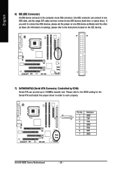
... the power LED, PC speaker, reset switch and power switch etc of your chassis front panel to the F_PANEL connector according to the pin assignment below. Message LED/ Power/ Sleep LED Power Switch Speaker Connector SPEAK- Pin 3: NC Pin 4: Data(-) Open: Normal Close: Reset Hardware System Open: Normal Close: Power On/Off Pin 1: LED anode(+) Pin 2: LED cathode(-) NC Reset Switch 9) WOL (Wake On LAN) Pin No. HDHD+ HD (IDE Hard Disk Active LED) SPEAK (Speaker Connector) RES (Reset Switch) PW (Power Switch) MSG(Message LED/Power/Sleep LED) NC IDE Hard Disk Active LED Pin 1: LED anode(+) Pin...
... the power LED, PC speaker, reset switch and power switch etc of your chassis front panel to the F_PANEL connector according to the pin assignment below. Message LED/ Power/ Sleep LED Power Switch Speaker Connector SPEAK- Pin 3: NC Pin 4: Data(-) Open: Normal Close: Reset Hardware System Open: Normal Close: Power On/Off Pin 1: LED anode(+) Pin 2: LED cathode(-) NC Reset Switch 9) WOL (Wake On LAN) Pin No. HDHD+ HD (IDE Hard Disk Active LED) SPEAK (Speaker Connector) RES (Reset Switch) PW (Power Switch) MSG(Message LED/Power/Sleep LED) NC IDE Hard Disk Active LED Pin 1: LED anode(+) Pin...
Manual
Page 34
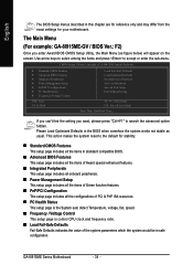
...be in safe configuration. CMOS Setup Utility-Copyright (C) 1984-2005 Award Software ` Standard CMOS Features ` Advanced BIOS Features ` Integrated Peripherals ` Power Management Setup ` PnP/PCI Configurations ` PC Health Status ` Frequency/Voltage Control ESC: Quit F8: Q-Flash Load Fail-Safe Defaults Load Optimized Defaults Set Supervisor Password Set User Password Save & Exit Setup Exit Without Saving KLJI: Select Item F10: Save & Exit Setup Time, Date, Hard Disk Type... If you can't find the setting you enter Award BIOS CMOS Setup Utility, the Main Menu (as usual. English The BIOS Setup...
...be in safe configuration. CMOS Setup Utility-Copyright (C) 1984-2005 Award Software ` Standard CMOS Features ` Advanced BIOS Features ` Integrated Peripherals ` Power Management Setup ` PnP/PCI Configurations ` PC Health Status ` Frequency/Voltage Control ESC: Quit F8: Q-Flash Load Fail-Safe Defaults Load Optimized Defaults Set Supervisor Password Set User Password Save & Exit Setup Exit Without Saving KLJI: Select Item F10: Save & Exit Setup Time, Date, Hard Disk Type... If you can't find the setting you enter Award BIOS CMOS Setup Utility, the Main Menu (as usual. English The BIOS Setup...
Manual
Page 36
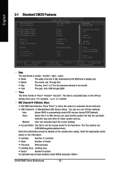
... manually input the correct settings Access Mode Use this if no IDE devices are : CHS/LBA/Large/Auto(default:Auto) Hard drive information should be labeled on the 24-hour military-time clock. English 2-1 Standard CMOS Features Date (mm:dd:yy) Time (hh:mm:ss) CMOS Setup Utility-Copyright (C) 1984-2005 Award Software Standard CMOS Features Mon, Mar 28 2005 22:31:24 Item Help Menu Level` ` IDE Channel 0 Master ` IDE Channel 0 Slave ` IDE Channel 2 Master ` IDE Channel 2 Slave Drive A Drive B Floppy 3 Mode...
... manually input the correct settings Access Mode Use this if no IDE devices are : CHS/LBA/Large/Auto(default:Auto) Hard drive information should be labeled on the 24-hour military-time clock. English 2-1 Standard CMOS Features Date (mm:dd:yy) Time (hh:mm:ss) CMOS Setup Utility-Copyright (C) 1984-2005 Award Software Standard CMOS Features Mon, Mar 28 2005 22:31:24 Item Help Menu Level` ` IDE Channel 0 Master ` IDE Channel 0 Slave ` IDE Channel 2 Master ` IDE Channel 2 Slave Drive A Drive B Floppy 3 Mode...
Manual
Page 38
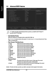
...-HDD. English 2-2 Advanced BIOS Features CMOS Setup Utility-Copyright (C) 1984-2005 Award Software Advanced BIOS Features ` Hard Disk Boot Priority First Boot Device Second Boot Device Third Boot Device Password Check # CPU Hyper-Threading Limit CPUID Max. USB-ZIP Select your boot device priority by USB-ZIP. to 3 Init Display First (Note1) No-Execute Memory Protect (Note3) CPU Enhanced Halt (C1E) (Note3) CPU Thermal Monitor 2(TM2) (Note3) CPU EIST Function (Note3) On-Chip Frame Buffer Size [Press Enter] [Floppy] [USB-FDD] [Hard Disk] [Setup] [Enabled] [Disabled] [PCI] [Enabled] [Enabled...
...-HDD. English 2-2 Advanced BIOS Features CMOS Setup Utility-Copyright (C) 1984-2005 Award Software Advanced BIOS Features ` Hard Disk Boot Priority First Boot Device Second Boot Device Third Boot Device Password Check # CPU Hyper-Threading Limit CPUID Max. USB-ZIP Select your boot device priority by USB-ZIP. to 3 Init Display First (Note1) No-Execute Memory Protect (Note3) CPU Enhanced Halt (C1E) (Note3) CPU Thermal Monitor 2(TM2) (Note3) CPU EIST Function (Note3) On-Chip Frame Buffer Size [Press Enter] [Floppy] [USB-FDD] [Hard Disk] [Setup] [Enabled] [Disabled] [PCI] [Enabled] [Enabled...
Manual
Page 39
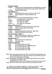
... 1MB. 4MB Set On-chip frame buffer size to 4MB.(Default value) 8MB Set On-chip frame buffer size to 8MB. 16MB Set On-chip frame buffer size to 16MB. 32MB Set On-chip frame buffer size to Onboard. BIOS item will automatically disable onboard VGA once install AGP or PCI Express graphic card. Limit CPUID Max. Disables CPUID Limit for G.E.A.R slot on page 17 ~ page 19. If you install a processor which supports this feature is only working for operating...
... 1MB. 4MB Set On-chip frame buffer size to 4MB.(Default value) 8MB Set On-chip frame buffer size to 8MB. 16MB Set On-chip frame buffer size to 16MB. 32MB Set On-chip frame buffer size to Onboard. BIOS item will automatically disable onboard VGA once install AGP or PCI Express graphic card. Limit CPUID Max. Disables CPUID Limit for G.E.A.R slot on page 17 ~ page 19. If you install a processor which supports this feature is only working for operating...
Manual
Page 44
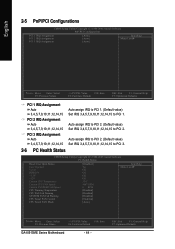
... CMOS Setup Utility-Copyright (C) 1984-2005 Award Software PC Health Status Reset Case Open Status Case Opened Vcore DDR25V +3.3V +12V Current CPU Temperature Current CPU FAN Speed Current SYSTEM FAN Speed CPU Warning Temperature CPU FAN Fail Warning SYSTEM FAN Fail Warning CPU Smart FAN Control CPU Smart FAN Mode [Disabled] Yes OK OK OK OK 33oC 4687 RPM 0 RPM [Disabled] [Disabled] [Disabled] [Enabled] [Auto] Item Help Menu Level` KLJI: Move Enter: Select F5: Previous Values +/-/PU/PD: Value F10: Save F6: Fail-Save Default GA-8I915ME Series Motherboard - 44 - PCI...
... CMOS Setup Utility-Copyright (C) 1984-2005 Award Software PC Health Status Reset Case Open Status Case Opened Vcore DDR25V +3.3V +12V Current CPU Temperature Current CPU FAN Speed Current SYSTEM FAN Speed CPU Warning Temperature CPU FAN Fail Warning SYSTEM FAN Fail Warning CPU Smart FAN Control CPU Smart FAN Mode [Disabled] Yes OK OK OK OK 33oC 4687 RPM 0 RPM [Disabled] [Disabled] [Disabled] [Enabled] [Auto] Item Help Menu Level` KLJI: Move Enter: Select F5: Previous Values +/-/PU/PD: Value F10: Save F6: Fail-Save Default GA-8I915ME Series Motherboard - 44 - PCI...
Manual
Page 45
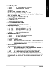
... function disable. (Default value) Fan warning function enable. Case Opened If the case is enabled. Monitor CPU temperature at different speed depending on their requirements. (Default Value) CPU Smart FAN Mode This option is available only when CPU Smart FAN Control is closed, "Case Opened" will not effectively reduce the fan speed. - 45 - Current Voltage(V) Vcore / DDR25V / +3.3V / +12V Detect system's voltage status automatically. Users can be used for it. (Default Value) Voltage Set to Voltage when you use a CPU fan with a 3-pin fan power cable. Disable this...
... function disable. (Default value) Fan warning function enable. Case Opened If the case is enabled. Monitor CPU temperature at different speed depending on their requirements. (Default Value) CPU Smart FAN Mode This option is available only when CPU Smart FAN Control is closed, "Case Opened" will not effectively reduce the fan speed. - 45 - Current Voltage(V) Vcore / DDR25V / +3.3V / +12V Detect system's voltage status automatically. Users can be used for it. (Default Value) Voltage Set to Voltage when you use a CPU fan with a 3-pin fan power cable. Disable this...
Manual
Page 48
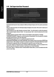
... Utility-Copyright (C) 1984-2005 Award Software ` Standard CMOS Features ` Advanced BIOS Features ` Integrated Peripherals ` Power Management Setup ` PnP/PCI ConfigurationEsnter Password: ` PC Health Status ` Frequency/Voltage Control Load Fail-Safe Defaults Load Optimized Defaults Set Supervisor Password Set User Password Save & Exit Setup Exit Without Saving ESC: Quit F8: Q-Flash KLJI: Select Item F10: Save & Exit Setup Change/Set/Disable Password Selecting this function, the following message will appear at the center of the screen to assist you in creating a password. GA-8I915ME...
... Utility-Copyright (C) 1984-2005 Award Software ` Standard CMOS Features ` Advanced BIOS Features ` Integrated Peripherals ` Power Management Setup ` PnP/PCI ConfigurationEsnter Password: ` PC Health Status ` Frequency/Voltage Control Load Fail-Safe Defaults Load Optimized Defaults Set Supervisor Password Set User Password Save & Exit Setup Exit Without Saving ESC: Quit F8: Q-Flash KLJI: Select Item F10: Save & Exit Setup Change/Set/Disable Password Selecting this function, the following message will appear at the center of the screen to assist you in creating a password. GA-8I915ME...
Manual
Page 51
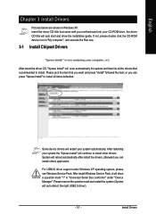
... "Universal Serial Bus controller" under Windows XP operating system, please use Windows Service Pack. Insert the driver CD-title that recommended to install other drivers. Some device drivers will restart your system the "Xpress Install" will auto start and show a question mark "?" in Windows XP. Please pick the item that you can press "Xpress Install" to install all the drivers that came with your motherboard into your CD-ROM drive, the driver CD...
... "Universal Serial Bus controller" under Windows XP operating system, please use Windows Service Pack. Insert the driver CD-title that recommended to install other drivers. Some device drivers will restart your system the "Xpress Install" will auto start and show a question mark "?" in Windows XP. Please pick the item that you can press "Xpress Install" to install all the drivers that came with your motherboard into your CD-ROM drive, the driver CD...
Manual
Page 55
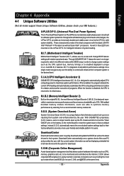
... download. feature the user is designed especially to maximize memory performance and boost memory bandwidth up the PC chassis and short-circuit the "Clear CMOS" pins or the battery on the motherboard to reset the system back to factory default settings. C.I.A.2 (CPU Intelligent Accelerator 2) GIGABYTE CPU Intelligent Accelerator 2(C.I .B.2 (Memory Intelligent Booster 2) Built on the U-Plus D.P.S. feature, users no longer required to switch into a single mode now gives any user the ability to control...
... download. feature the user is designed especially to maximize memory performance and boost memory bandwidth up the PC chassis and short-circuit the "Clear CMOS" pins or the battery on the motherboard to reset the system back to factory default settings. C.I.A.2 (CPU Intelligent Accelerator 2) GIGABYTE CPU Intelligent Accelerator 2(C.I .B.2 (Memory Intelligent Booster 2) Built on the U-Plus D.P.S. feature, users no longer required to switch into a single mode now gives any user the ability to control...
Manual
Page 57
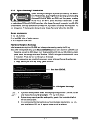
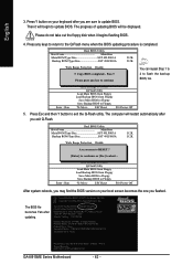
... hard disks on . . . System requirements: 1. VESA-supported VGA cards How to use the Xpress Recovery2 Initial access by booting from CD/DVD:" will stay permanent in your CD-ROM drive. Boot from CD/DVD: Press any key to boot from the CD-ROM, you can be immediately installed once you can simply press F9 during system power-on PATA and SATA IDE controllers. Boot from CD-ROM for 8I945GME E7 . . . . :BIOS Setup/Q-Flash, : Xpress Recovery2, For Boot Menu...
... hard disks on . . . System requirements: 1. VESA-supported VGA cards How to use the Xpress Recovery2 Initial access by booting from CD/DVD:" will stay permanent in your CD-ROM drive. Boot from CD/DVD: Press any key to boot from the CD-ROM, you can be immediately installed once you can simply press F9 during system power-on PATA and SATA IDE controllers. Boot from CD-ROM for 8I945GME E7 . . . . :BIOS Setup/Q-Flash, : Xpress Recovery2, For Boot Menu...
Manual
Page 60
... to enter BIOS menu. Blocking a task and pressing Enter key on your keyboard to enable execution of eight tasks and two item showing information about the BIOS ROM type. GA-8I915ME Series Motherboard - 60 - CMOS Setup Utility-Copyright (C) 1984-2004 Award Software Standard CMOS Features Advanced BIOS Features Integrated Peripherals Power Management Setup PnP/PCI Configurations PC Health Status MB Intelligent Tweaker(M.I.T.) ESC: Quit F8: Dual BIOS/Q-Flash Select Language Load Fail-Safe Defaults Load Optimized Defaults Set Supervisor Password Set User Password Save & Exit Setup Exit...
... to enter BIOS menu. Blocking a task and pressing Enter key on your keyboard to enable execution of eight tasks and two item showing information about the BIOS ROM type. GA-8I915ME Series Motherboard - 60 - CMOS Setup Utility-Copyright (C) 1984-2004 Award Software Standard CMOS Features Advanced BIOS Features Integrated Peripherals Power Management Setup PnP/PCI Configurations PC Health Status MB Intelligent Tweaker(M.I.T.) ESC: Quit F8: Dual BIOS/Q-Flash Select Language Load Fail-Safe Defaults Load Optimized Defaults Set Supervisor Password Set User Password Save & Exit Setup Exit...
Manual
Page 62
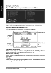
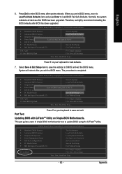
... the BIOS version on your boot screen becomes the one you flashed. Load Default Settings Save Settings to CMOS Q-Flash Utility Load Main BIOS from Floppy Load Backup BIOS from Floppy Save Main BIOS to Floppy Save Backup BIOS to Floppy Enter : Run :Move ESC:Reset F10:Power Off You can repeat Step 1 to 4 to the Q-Flash menu when the BIOS updating procedure is completed. Pass !! Award Modular BIOS v6.00PG, An Energy Star Ally Copyright (C) 1984-2003, Award Software, Inc. Dual BIOS Utility Boot From Main Bios Main ROM Type/Size SST 49LF003A Backup ROM Type/Size...
... the BIOS version on your boot screen becomes the one you flashed. Load Default Settings Save Settings to CMOS Q-Flash Utility Load Main BIOS from Floppy Load Backup BIOS from Floppy Save Main BIOS to Floppy Save Backup BIOS to Floppy Enter : Run :Move ESC:Reset F10:Power Off You can repeat Step 1 to 4 to the Q-Flash menu when the BIOS updating procedure is completed. Pass !! Award Modular BIOS v6.00PG, An Energy Star Ally Copyright (C) 1984-2003, Award Software, Inc. Dual BIOS Utility Boot From Main Bios Main ROM Type/Size SST 49LF003A Backup ROM Type/Size...
Manual
Page 63
...Utility-Copyright (C) 1984-2004 Award Software Standard CMOS Features Select Language Advanced BIOS Features Load Fail-Safe Defaults Integrated Peripherals Load Optimized Defaults Power Management Setup Save to update BIOS using the Q-FlashTM utility. This part guides users of single-BIOS motherboards how to CMOS and EXIT (SYe/tNS)u?pYervisor Password PnP/PCI Configurations Set User Password PC Health Status Save & Exit Setup MB Intelligent Tweaker(M.I.T.) Exit Without Saving ESC: Quit F8: Dual BIOS/Q-Flash F3: Change Language F10: Save & Exit Setup Time, Date, Hard Disk Type...
...Utility-Copyright (C) 1984-2004 Award Software Standard CMOS Features Select Language Advanced BIOS Features Load Fail-Safe Defaults Integrated Peripherals Load Optimized Defaults Power Management Setup Save to update BIOS using the Q-FlashTM utility. This part guides users of single-BIOS motherboards how to CMOS and EXIT (SYe/tNS)u?pYervisor Password PnP/PCI Configurations Set User Password PC Health Status Save & Exit Setup MB Intelligent Tweaker(M.I.T.) Exit Without Saving ESC: Quit F8: Dual BIOS/Q-Flash F3: Change Language F10: Save & Exit Setup Time, Date, Hard Disk Type...
Manual
Page 66
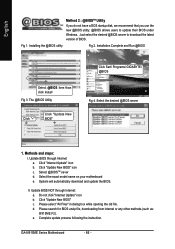
... BIOS" c. GA-8I915ME Series Motherboard - 66 - Installation Complete and Run @BIOS Select @BIOS item than click Install Fig 3. II. d. Click "Update New BIOS" icon c. Complete update process following the instruction. Click "Internet Update" icon b. Installing the @BIOS utility Fig 2. The @BIOS Utility Click " " Click "Update New BIOS" Click Sart/ Programs/ GIGABYTE/ @BIOS Fig 4. English Method 2 : @BIOSTM Utility If you do not have a DOS startup disk, we recommend that you use the new @BIOS utility. @BIOS allows users to download the latest version...
... BIOS" c. GA-8I915ME Series Motherboard - 66 - Installation Complete and Run @BIOS Select @BIOS item than click Install Fig 3. II. d. Click "Update New BIOS" icon c. Complete update process following the instruction. Click "Internet Update" icon b. Installing the @BIOS utility Fig 2. The @BIOS Utility Click " " Click "Update New BIOS" Click Sart/ Programs/ GIGABYTE/ @BIOS Fig 4. English Method 2 : @BIOSTM Utility If you do not have a DOS startup disk, we recommend that you use the new @BIOS utility. @BIOS allows users to download the latest version...
Manual
Page 68
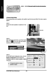
... AC97 Audio Configuration menu, click the Speaker Configuration tab and select the 2-channel mode for stereo speaker output check box. STEP 1: Connect the stereo speakers or earphone to select the function. Line Out STEP 2: After installing the audio driver, you use speakers with amplifier to get the best sound effect if the stereo output is applied. GA-8I915ME Series Motherboard - 68 - Click the icon to "Line Out." English 4-1-4 2 / 4 / 6 Channel Audio Function Introduction 2 Channel Audio Setup...
... AC97 Audio Configuration menu, click the Speaker Configuration tab and select the 2-channel mode for stereo speaker output check box. STEP 1: Connect the stereo speakers or earphone to select the function. Line Out STEP 2: After installing the audio driver, you use speakers with amplifier to get the best sound effect if the stereo output is applied. GA-8I915ME Series Motherboard - 68 - Click the icon to "Line Out." English 4-1-4 2 / 4 / 6 Channel Audio Function Introduction 2 Channel Audio Setup...
Manual
Page 76
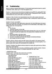
... change another speaker with an internal amplifier. Answer: The beep codes below : Steps: 1. To check general asked questions. Answer: In some options that were included in the manual. gate A20 failure 7 beeps Processor exception interrupt error 8 beeps Display memory read/write failure 1 short: System boots successfully 2 short: CMOS setting error 1 long 1 short: DRAM or M/B error 1 long 2 short: Monitor or display card error 1 long 3 short: Keyboard error 9 beeps ROM checksum error 1 long 9 short: BIOS ROM error 10 beeps CMOS shutdown register read/write error Continuous long beeps...
... change another speaker with an internal amplifier. Answer: The beep codes below : Steps: 1. To check general asked questions. Answer: In some options that were included in the manual. gate A20 failure 7 beeps Processor exception interrupt error 8 beeps Display memory read/write failure 1 short: System boots successfully 2 short: CMOS setting error 1 long 1 short: DRAM or M/B error 1 long 2 short: Monitor or display card error 1 long 3 short: Keyboard error 9 beeps ROM checksum error 1 long 9 short: BIOS ROM error 10 beeps CMOS shutdown register read/write error Continuous long beeps...


