Manual
Page 1
GA-8I915ME Series Intel® Pentium® 4 LGA775 Processor Motherboard User's Manual Rev. 1003 12ME-I915MES-1003 * The WEEE marking on the product indicates this product must not be disposed of with user's other household waste and must be handed over to a designated collection point for the recycling of waste electrical and electronic equipment!! * The WEEE marking applies only in European Union's member states.
GA-8I915ME Series Intel® Pentium® 4 LGA775 Processor Motherboard User's Manual Rev. 1003 12ME-I915MES-1003 * The WEEE marking on the product indicates this product must not be disposed of with user's other household waste and must be handed over to a designated collection point for the recycling of waste electrical and electronic equipment!! * The WEEE marking applies only in European Union's member states.
Manual
Page 2
Motherboard GA-8I915ME May 27, 2005 Motherboard GA-8I915ME May 27, 2005
Motherboard GA-8I915ME May 27, 2005 Motherboard GA-8I915ME May 27, 2005
Manual
Page 3
... Manual". „ For detailed information related to Gigabyte's unique features, please go to "Technology Guide" section on Gigabyte's website to their respective companies. For more product details, please click onto Gigabyte's website at www.gigabyte.com.tw Specifications and features are legally registered to... read or download the information you need. Product Manual Classification In order to change without Gigabyte's prior written permission. Copyright © 2005 GIGA-BYTE TECHNOLOGY CO., LTD. The trademarks mentioned in any form or...
... Manual". „ For detailed information related to Gigabyte's unique features, please go to "Technology Guide" section on Gigabyte's website to their respective companies. For more product details, please click onto Gigabyte's website at www.gigabyte.com.tw Specifications and features are legally registered to... read or download the information you need. Product Manual Classification In order to change without Gigabyte's prior written permission. Copyright © 2005 GIGA-BYTE TECHNOLOGY CO., LTD. The trademarks mentioned in any form or...

Manual
Page 4
Table of Content GA-8I915ME Series Motherboard Layout 6 Block Diagram ...7 Chapter 1 Hardware Installation 9 1-1 Considerations Prior to Installation 9 1-2 Feature Summary 10 1-3 Installation of the CPU and Heatsink 12 ...is G.E.A.R 17 1-5-2 Graphics Card Support List 17 1-6 I/O Back Panel Introduction 20 1-7 Connectors Introduction 21 Chapter 2 BIOS Setup 33 The Main Menu ...34 (For example: GA-8I915ME-GV / BIOS Ver.: F2 34 2-1 Standard CMOS Features 36 2-2 Advanced BIOS Features 38 2-3 IntegratedPeripherals 40 2-4 Power Management Setup 42 2-5 PnP/PCI Configurations 44 2-6 PC...
Table of Content GA-8I915ME Series Motherboard Layout 6 Block Diagram ...7 Chapter 1 Hardware Installation 9 1-1 Considerations Prior to Installation 9 1-2 Feature Summary 10 1-3 Installation of the CPU and Heatsink 12 ...is G.E.A.R 17 1-5-2 Graphics Card Support List 17 1-6 I/O Back Panel Introduction 20 1-7 Connectors Introduction 21 Chapter 2 BIOS Setup 33 The Main Menu ...34 (For example: GA-8I915ME-GV / BIOS Ver.: F2 34 2-1 Standard CMOS Features 36 2-2 Advanced BIOS Features 38 2-3 IntegratedPeripherals 40 2-4 Power Management Setup 42 2-5 PnP/PCI Configurations 44 2-6 PC...

Manual
Page 5
Chapter 3 Install Drivers 51 3-1 Install Chipset Drivers 51 3-2 SoftwareApplications 52 3-3 Driver CD Information 52 3-4 Hardware Information 53 3-5 Contact Us ...53 Chapter 4 Appendix ...55 4-1 Unique Software Utilities 55 4-1-1 EasyTune 5 Introduction 56 4-1-2 Xpress Recovery2 Introduction 57 4-1-3 Flash BIOS Method Introduction 60 4-1-4 2- / 4- / 6- Channel Audio Function Introduction 69 4-1-5 Jack-Sensing Introduction 75 4-2 Troubleshooting 77 - 5 -
Chapter 3 Install Drivers 51 3-1 Install Chipset Drivers 51 3-2 SoftwareApplications 52 3-3 Driver CD Information 52 3-4 Hardware Information 53 3-5 Contact Us ...53 Chapter 4 Appendix ...55 4-1 Unique Software Utilities 55 4-1-1 EasyTune 5 Introduction 56 4-1-2 Xpress Recovery2 Introduction 57 4-1-3 Flash BIOS Method Introduction 60 4-1-4 2- / 4- / 6- Channel Audio Function Introduction 69 4-1-5 Jack-Sensing Introduction 75 4-2 Troubleshooting 77 - 5 -
Manual
Page 6
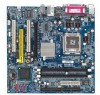
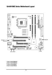
Only for GA-8I915ME-GL. Only for GA-8I915ME-G. - 6 - Only for GA-8I915ME-GV. GA-8I915ME Series Motherboard Layout IT8712F CI KB_MS ATX_12V CPU_FAN COM1 LPT GA-8I915ME ATX SYS_FAN FDD VGA LGA775 R_USB LAN USB F_AUDIO AUDIO1 SUR_CEN PCIE_16 Intel 915GV Intel 915GL Intel 910GL Intel 915G DIMM1 DIMM2 IDE RTL8100C RTL8110S PCI1 GEAR ICH6 -C -G -GL -GV PCI2 CODEC SPDIF_IO BUZZER F_USB1 F_USB2 BAT COM2 WOL CLR_CMOS BIOS SATA2 SATA0 BIOS_WP PWR_LED CD_IN AUX_IN F_PANEL Only for GA-8I915ME-C.
Only for GA-8I915ME-GL. Only for GA-8I915ME-G. - 6 - Only for GA-8I915ME-GV. GA-8I915ME Series Motherboard Layout IT8712F CI KB_MS ATX_12V CPU_FAN COM1 LPT GA-8I915ME ATX SYS_FAN FDD VGA LGA775 R_USB LAN USB F_AUDIO AUDIO1 SUR_CEN PCIE_16 Intel 915GV Intel 915GL Intel 910GL Intel 915G DIMM1 DIMM2 IDE RTL8100C RTL8110S PCI1 GEAR ICH6 -C -G -GL -GV PCI2 CODEC SPDIF_IO BUZZER F_USB1 F_USB2 BAT COM2 WOL CLR_CMOS BIOS SATA2 SATA0 BIOS_WP PWR_LED CD_IN AUX_IN F_PANEL Only for GA-8I915ME-C.
Manual
Page 7
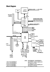
... (33MHz) MIC Line-Out Line-In SPDIF In SPDIF Out Only for GA-8I915ME-GL. Only for GA-8I915ME-GV. Only for GA-8I915ME-C. GA-8I915ME-GV / GA-8I915ME-GL / GA-8I915ME-C supports transfer up to PCI Express x4 mode. GA-8I915ME-G supports transfer up to PCI Express x16 mode. Only for GA-8I915ME-G. (Note) - 7 - Block Diagram VGA LGA775 Processor CPUCLK+/-(200 /133 MHz) PCI-ECLK...
... (33MHz) MIC Line-Out Line-In SPDIF In SPDIF Out Only for GA-8I915ME-GL. Only for GA-8I915ME-GV. Only for GA-8I915ME-C. GA-8I915ME-GV / GA-8I915ME-GL / GA-8I915ME-C supports transfer up to PCI Express x4 mode. GA-8I915ME-G supports transfer up to PCI Express x16 mode. Only for GA-8I915ME-G. (Note) - 7 - Block Diagram VGA LGA775 Processor CPUCLK+/-(200 /133 MHz) PCI-ECLK...
Manual
Page 9
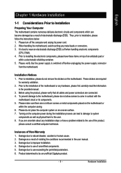
... parameters. 6. Product determined to installation, please do not place the computer system on the motherboard or within a electrostatic shielding container. 5. Prior to be an unofficial Gigabyte product. - 9 - English Chapter 1 Hardware Installation 1-1 Considerations Prior to installation, please follow the instructions below: 1. It is switched off the computer and unplug its components. 5. Damage...
... parameters. 6. Product determined to installation, please do not place the computer system on the motherboard or within a electrostatic shielding container. 5. Prior to be an unofficial Gigabyte product. - 9 - English Chapter 1 Hardware Installation 1-1 Considerations Prior to installation, please follow the instructions below: 1. It is switched off the computer and unplug its components. 5. Damage...
Manual
Page 10
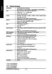
... dual channel DDR400/333 DIMM Š Supports 2.5V DDR DIMM Š 1 PCI Express x 16 slot (Note 2) Š 1 G.E.A.R. Only for GA-8I915ME-GV. GA-8I915ME Series Motherboard - 10 - MIC In Š Supports 2 / 4 / 6 channel audio Š SPDIF In / Out connection Š CD In... Š Supported on the Win 2000/XP operating systems Š IT8712F Only for GA-8I915ME-GL. English 1-2 Feature Summary Motherboard CPU Š GA-8I915ME Series motherboard -GA-8I915ME-GV / GA-8I915ME-GL / GA-8I915ME-C / GA-8I915ME-G Š Supports the latest Intel® Pentium® 4 LGA775 CPU Š...
... dual channel DDR400/333 DIMM Š Supports 2.5V DDR DIMM Š 1 PCI Express x 16 slot (Note 2) Š 1 G.E.A.R. Only for GA-8I915ME-GV. GA-8I915ME Series Motherboard - 10 - MIC In Š Supports 2 / 4 / 6 channel audio Š SPDIF In / Out connection Š CD In... Š Supported on the Win 2000/XP operating systems Š IT8712F Only for GA-8I915ME-GL. English 1-2 Feature Summary Motherboard CPU Š GA-8I915ME Series motherboard -GA-8I915ME-GV / GA-8I915ME-GL / GA-8I915ME-C / GA-8I915ME-G Š Supports the latest Intel® Pentium® 4 LGA775 CPU Š...
Manual
Page 11
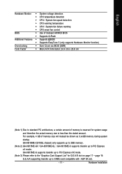
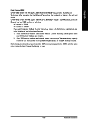
...architecture, a certain amount of memory size will instead be shown as 3.xxGB memory during system startup. GA-8I915ME-C(910GL chipset) only supports up to 2GB memory. (Note 2) GA-8I915ME-GV / GA-8I915ME-GL / GA-8I915ME-C supports transfer up to 33MHz and compatible with AGP 8X slot. - 11 - G.E.A.R supporting transfer ...the "Graphics Card Support List" for system usage and therefore the actual memory size is less than the stated amount. Hardware Installation GA-8I915ME-G supports transfer up to PCI Express x16 mode. (Note 3) Please refer to PCI Express x4 mode. For example, 4 GB...
...architecture, a certain amount of memory size will instead be shown as 3.xxGB memory during system startup. GA-8I915ME-C(910GL chipset) only supports up to 2GB memory. (Note 2) GA-8I915ME-GV / GA-8I915ME-GL / GA-8I915ME-C supports transfer up to 33MHz and compatible with AGP 8X slot. - 11 - G.E.A.R supporting transfer ...the "Graphics Card Support List" for system usage and therefore the actual memory size is less than the stated amount. Hardware Installation GA-8I915ME-G supports transfer up to PCI Express x16 mode. (Note 3) Please refer to PCI Express x4 mode. For example, 4 GB...
Manual
Page 12
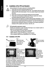
... for HT Technology 1-3-1 Installation of the CPU Metal Lever Fig. 1 Gently lift the metal lever located on the CPU prior to the CPU during installation.) GA-8I915ME Series Motherboard - 12 - Fig. 3 Notice the small gold colored triangle located on the CPU socket. If this occurs, please change the insert direction of the...
... for HT Technology 1-3-1 Installation of the CPU Metal Lever Fig. 1 Gently lift the metal lever located on the CPU prior to the CPU during installation.) GA-8I915ME Series Motherboard - 12 - Fig. 3 Notice the small gold colored triangle located on the CPU socket. If this occurs, please change the insert direction of the...
Manual
Page 13
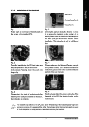
If the push pin is inserted as a result of hardening of the heatsink paste.To prevent such an occurrence, it is suggested that either thermal tape rather than heat sink paste be used for Intel boxed fan) Fig. 3 Place the heatsink atop the CPU and make sure the Male and Female push pin are joined closely. (for detailed installation instructions, please refer to the heatsink installation section of the user manual) Fig. 5 Please check the back of arrow sign on the motherboard.Pressing down the push pins diagonally. Fig. 6 Finally, please attach the power connector of the installed CPU. ...
If the push pin is inserted as a result of hardening of the heatsink paste.To prevent such an occurrence, it is suggested that either thermal tape rather than heat sink paste be used for Intel boxed fan) Fig. 3 Place the heatsink atop the CPU and make sure the Male and Female push pin are joined closely. (for detailed installation instructions, please refer to the heatsink installation section of the user manual) Fig. 5 Please check the back of arrow sign on the motherboard.Pressing down the push pins diagonally. Fig. 6 Finally, please attach the power connector of the installed CPU. ...
Manual
Page 14
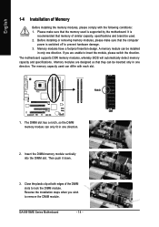
... module. Reverse the installation steps when you are designed so that the computer power is switched off to insert the module, please switch the direction. GA-8I915ME Series Motherboard - 14 - If you wish to lock the DIMM module. Insert the DIMM memory module vertically into the DIMM slot. A memory module can only...
... module. Reverse the installation steps when you are designed so that the computer power is switched off to insert the module, please switch the direction. GA-8I915ME Series Motherboard - 14 - If you wish to lock the DIMM module. Insert the DIMM memory module vertically into the DIMM slot. A memory module can only...
Manual
Page 15
After operating the Dual Channel Technology, the bandwidth of Intel chipset specifications. 1. Hardware Installation GA-8I915ME-GV/GA-8I915ME-GL/GA-8I915ME-C/GA-8I915ME-G includes 2 DIMM sockets, and each Channel has two DIMM sockets as following: Channel A : DIMM1 Channel B : DIMM2 If you...and for Dual Channel Technology to work. - 15 - If two DDR memory modules are installed. 2. English Dual Channel DDR GA-8I915ME-GV/GA-8I915ME-GL/GA-8I915ME-C/GA-8I915ME-G supports the Dual Channel Technology. We'll strongly recommend our user to slot two DDR memory modules into the DIMMs with the...
After operating the Dual Channel Technology, the bandwidth of Intel chipset specifications. 1. Hardware Installation GA-8I915ME-GV/GA-8I915ME-GL/GA-8I915ME-C/GA-8I915ME-G includes 2 DIMM sockets, and each Channel has two DIMM sockets as following: Channel A : DIMM1 Channel B : DIMM2 If you...and for Dual Channel Technology to work. - 15 - If two DDR memory modules are installed. 2. English Dual Channel DDR GA-8I915ME-GV/GA-8I915ME-GL/GA-8I915ME-C/GA-8I915ME-G supports the Dual Channel Technology. We'll strongly recommend our user to slot two DDR memory modules into the DIMMs with the...
Manual
Page 16
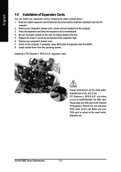
... before install the expansion card into expansion slot in the slot. 5. Power on the computer, if necessary, setup BIOS utility of the PCI Express x 16/G.E.A.R. GA-8I915ME Series Motherboard - 16 -
... before install the expansion card into expansion slot in the slot. 5. Power on the computer, if necessary, setup BIOS utility of the PCI Express x 16/G.E.A.R. GA-8I915ME Series Motherboard - 16 -
Manual
Page 17
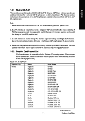
...card.) Figure 1-1. 4X AGP Card Graphics Chip Nvidia Maker Gigabyte Gigabyte Gigabyte Gigabyte Model Name GA-620 GA-622 GA-660 Plus GA-GF2560 Gigabyte Gigabyte Gigabyte Gigabyte Gigabyte Gigabyte GA-GF2000 GA-GF1280 GV-GF2010D GA-GF3000D GV-GF1280-32E GV-GF1280T-32P Gigabyte Gigabyte ELSA G V-GF3200TF G V-GF3500TF-GH Gladiac Ultra ELSA ELSA...Intel chipset based PCI Express solution motherboard. Please view the graphics cards support list currently validated by GIGABYTE enginneers. Hardware Installation When using an add-on graphics card, please first delete the onboard graphics ...
...card.) Figure 1-1. 4X AGP Card Graphics Chip Nvidia Maker Gigabyte Gigabyte Gigabyte Gigabyte Model Name GA-620 GA-622 GA-660 Plus GA-GF2560 Gigabyte Gigabyte Gigabyte Gigabyte Gigabyte Gigabyte GA-GF2000 GA-GF1280 GV-GF2010D GA-GF3000D GV-GF1280-32E GV-GF1280T-32P Gigabyte Gigabyte ELSA G V-GF3200TF G V-GF3500TF-GH Gladiac Ultra ELSA ELSA...Intel chipset based PCI Express solution motherboard. Please view the graphics cards support list currently validated by GIGABYTE enginneers. Hardware Installation When using an add-on graphics card, please first delete the onboard graphics ...
Manual
Page 20
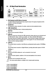
...The provided Internet connection is fast Ethernet, providing data transfer speeds of 10/100Mbps. Only for possible patch or driver upgrade. GA-8I915ME Series Motherboard - 20 - English 1-6 I/O Back Panel Introduction PS/2 Keyboard and PS/2 Mouse Connector To install a PS/2...controller. Also make sure your OS or device(s) vendors. Only for GA-8I915ME-G. can be connected to this connector. Only for GA-8I915ME-C. MIC In Microphone can be connected to configure 2-/4-/6- Only for GA-8I915ME-GV. Line Out Connect the stereo speakers, earphone or front surround ...
...The provided Internet connection is fast Ethernet, providing data transfer speeds of 10/100Mbps. Only for possible patch or driver upgrade. GA-8I915ME Series Motherboard - 20 - English 1-6 I/O Back Panel Introduction PS/2 Keyboard and PS/2 Mouse Connector To install a PS/2...controller. Also make sure your OS or device(s) vendors. Only for GA-8I915ME-G. can be connected to this connector. Only for GA-8I915ME-C. MIC In Microphone can be connected to configure 2-/4-/6- Only for GA-8I915ME-GV. Line Out Connect the stereo speakers, earphone or front surround ...
Manual
Page 21
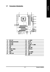
Hardware Installation English 1-7 Connectors Introduction 1 3 2 18 5 4 6 11 16 20 7 19 10 8 12 13 17 15 9 14 21 1) ATX_12V 2) ATX (Power Connector) 3) CPU_FAN 4) SYS_FAN 5) FDD 6) IDE 7) SATA0 / SATA2 8) F_PANEL 9) WOL 10) PWR_LED 11) F_AUDIO 12) CD_IN 13) AUX_IN 14) F_USB1 / F_USB2 15) COM2 16) SUR_CEN 17) SPIDF_IO 18) CI 19) CLR_CMOS 20) BIOS_WP 21) BAT - 21 -
Hardware Installation English 1-7 Connectors Introduction 1 3 2 18 5 4 6 11 16 20 7 19 10 8 12 13 17 15 9 14 21 1) ATX_12V 2) ATX (Power Connector) 3) CPU_FAN 4) SYS_FAN 5) FDD 6) IDE 7) SATA0 / SATA2 8) F_PANEL 9) WOL 10) PWR_LED 11) F_AUDIO 12) CD_IN 13) AUX_IN 14) F_USB1 / F_USB2 15) COM2 16) SUR_CEN 17) SPIDF_IO 18) CI 19) CLR_CMOS 20) BIOS_WP 21) BAT - 21 -
Manual
Page 22
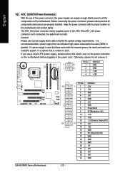
... power to start . Before connecting the power connector, please make sure that is not connected, the system will not start . Definition 3 4 1 GND 1 2 2 GND 3 +12V 4 +12V GA-8I915ME Series Motherboard 13 24 - 22 - It is unable to all components and devices are properly installed. Pin No. 1 1 2 3 4 5 6 7 8 9 10 11 12 12 13 14 15...
... power to start . Before connecting the power connector, please make sure that is not connected, the system will not start . Definition 3 4 1 GND 1 2 2 GND 3 +12V 4 +12V GA-8I915ME Series Motherboard 13 24 - 22 - It is unable to all components and devices are properly installed. Pin No. 1 1 2 3 4 5 6 7 8 9 10 11 12 12 13 14 15...
Manual
Page 23
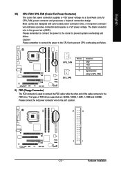
Hardware Installation Please remember to connect the power to the cooler to the pin1 position. 34 33 2 1 - 23 - The black connector wire is used to connect the FDD cable while the other end of FDD drives supported are designed with color-coded power connector wires. Please remember to connect the power to the CPU fan to the FDD drive. The types of the cable connects to prevent CPU overheating and failure. 1 CPU_FAN 1 SYS_FAN Pin No. 1 2 3 4 Definition GND +12V Sense Speed Control (Only for CPU_FAN) power connector and possesses a foolproof connection design. Most ...
Hardware Installation Please remember to connect the power to the cooler to the pin1 position. 34 33 2 1 - 23 - The black connector wire is used to connect the FDD cable while the other end of FDD drives supported are designed with color-coded power connector wires. Please remember to connect the power to the CPU fan to the FDD drive. The types of the cable connects to prevent CPU overheating and failure. 1 CPU_FAN 1 SYS_FAN Pin No. 1 2 3 4 Definition GND +12V Sense Speed Control (Only for CPU_FAN) power connector and possesses a foolproof connection design. Most ...