Manual
Page 1
GA-8I915G Pro Intel® Pentium® 4 LGA775 Processor Motherboard User's Manual Rev. 1002 12ME-8I915GP-1002
GA-8I915G Pro Intel® Pentium® 4 LGA775 Processor Motherboard User's Manual Rev. 1002 12ME-8I915GP-1002
Manual
Page 2
Motherboard GA-8I915G Pro Jun.11, 2004 Motherboard GA-8I915G Pro Jun. 11, 2004
Motherboard GA-8I915G Pro Jun.11, 2004 Motherboard GA-8I915G Pro Jun. 11, 2004
Manual
Page 4
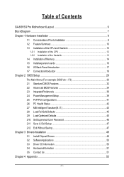
Table of Contents GA-8I915G Pro Motherboard Layout 6 Block Diagram ...7 Chapter 1 Hardware Installation 9 1-1 Considerations Priorto Installation 9 1-2 Feature Summary 10 1-3 Installation of the CPU and Heatsink 12 1-3-1 Installation of the CPU 12 1-3-2 Installation ...
Table of Contents GA-8I915G Pro Motherboard Layout 6 Block Diagram ...7 Chapter 1 Hardware Installation 9 1-1 Considerations Priorto Installation 9 1-2 Feature Summary 10 1-3 Installation of the CPU and Heatsink 12 1-3-1 Installation of the CPU 12 1-3-2 Installation ...
Manual
Page 6
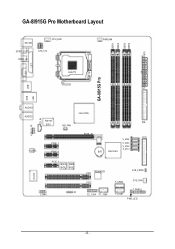
DDR1 DDR2 DDR3 DDR4 ATX GA-8I915G Pro Motherboard Layout KB_MS SP DIF_O UT SPDI F_IN C PU _FAN ATX_12V LGA 775 PWR_FAN VGA LPT GA-8I915G Pro USB LAN USB AUDIO1 AUDIO2 I ntel 915G M arv ell IDE 8001 N B_ FAN AZALIA_FP CD_IN C ODEC PCI E_1 PCI E_2 PC IE_16 FDD S_ ATA4 S_ ATA3 S_ ATA2 S_ ATA1 BAT Intel IC H6 IT8712 PCI E_3 BACK MAIN BIOS BIOS IR COMA PCI1 TS B43AB 23 PCI2 F2_1394 F1_1394 C LR_ C M OS F_U SB2 SYS_FAN F_U SB1 F_PAN EL P WR_LE D - 6 -
DDR1 DDR2 DDR3 DDR4 ATX GA-8I915G Pro Motherboard Layout KB_MS SP DIF_O UT SPDI F_IN C PU _FAN ATX_12V LGA 775 PWR_FAN VGA LPT GA-8I915G Pro USB LAN USB AUDIO1 AUDIO2 I ntel 915G M arv ell IDE 8001 N B_ FAN AZALIA_FP CD_IN C ODEC PCI E_1 PCI E_2 PC IE_16 FDD S_ ATA4 S_ ATA3 S_ ATA2 S_ ATA1 BAT Intel IC H6 IT8712 PCI E_3 BACK MAIN BIOS BIOS IR COMA PCI1 TS B43AB 23 PCI2 F2_1394 F1_1394 C LR_ C M OS F_U SB2 SYS_FAN F_U SB1 F_PAN EL P WR_LE D - 6 -

Manual
Page 9
...violating the conditions recommended in the user manual. 3. Damage due to be an unofficial Gigabyte product. - 9 - Product determined to improper installation. 4. Thus, prior to the user. 8. Turning on the motherboard. Damage due to use of uncertified components. 5. Installation Notices 1. To prevent damage... do not remove the stickers on the computer power during the installation process can become damaged as a result of the motherboard or any hardware, please first carefully read the information in the provided manual. 3. English Chapter 1 Hardware Installation 1-1 ...
...violating the conditions recommended in the user manual. 3. Damage due to be an unofficial Gigabyte product. - 9 - Product determined to improper installation. 4. Thus, prior to the user. 8. Turning on the motherboard. Damage due to use of uncertified components. 5. Installation Notices 1. To prevent damage... do not remove the stickers on the computer power during the installation process can become damaged as a result of the motherboard or any hardware, please first carefully read the information in the provided manual. 3. English Chapter 1 Hardware Installation 1-1 ...

Manual
Page 10
... to standard PC architecture, a certain amount of memory is reserved for system usage and therefore the actual memory size is less than the stated amount. GA-8I915G Pro Motherboard - 10 - Line Out ;
... to standard PC architecture, a certain amount of memory is reserved for system usage and therefore the actual memory size is less than the stated amount. GA-8I915G Pro Motherboard - 10 - Line Out ;

Manual
Page 12
... 1-3-1 Installation of the CPU Metal Lever Fig. 1 Gently lift the metal lever located on the CPU socket to the CPU during installation.) GA-8I915G Pro Motherboard - 12 - If you wish to set the CPU host frequency in accordance with the processor specifications. Fig. 2 Rem ov e the ... to the upright position. If this occurs, please change the insert direction of the CPU. Chipset: An Intel® Chipset that the motherboard supports the CPU. 2. English 1-3 Installation of the CPU and Heatsink Before installing the CPU, please comply with the following platform components: ...
... 1-3-1 Installation of the CPU Metal Lever Fig. 1 Gently lift the metal lever located on the CPU socket to the CPU during installation.) GA-8I915G Pro Motherboard - 12 - If you wish to set the CPU host frequency in accordance with the processor specifications. Fig. 2 Rem ov e the ... to the upright position. If this occurs, please change the insert direction of the CPU. Chipset: An Intel® Chipset that the motherboard supports the CPU. 2. English 1-3 Installation of the CPU and Heatsink Before installing the CPU, please comply with the following platform components: ...

Manual
Page 14
... , speci fi cati ons and brand be ins talled in one direction due to prevent hardware damage. 3 . It is supported by the motherboard. If you wish to remove the DIMM m odule. Memory size can only fit in only one direction. Reverse the installation steps when you ... Fig.1 The DIMM socket has a notch, so the DIMM memory module can only fitin one direction. To install the memory module, just push it down. GA-8I915G Pro Motherboard - 14 - The DIMM module can vary between sockets. Before i ns tall ing or remov ing memory modules, pleas e mak e sure that the memory used...
... , speci fi cati ons and brand be ins talled in one direction due to prevent hardware damage. 3 . It is supported by the motherboard. If you wish to remove the DIMM m odule. Memory size can only fit in only one direction. Reverse the installation steps when you ... Fig.1 The DIMM socket has a notch, so the DIMM memory module can only fitin one direction. To install the memory module, just push it down. GA-8I915G Pro Motherboard - 14 - The DIMM module can vary between sockets. Before i ns tall ing or remov ing memory modules, pleas e mak e sure that the memory used...
Manual
Page 16
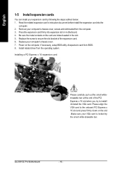
... related expansion card's instruction document before install the expansion card into expansion slot in the slot. 5. Remove your computer's chassis cover. 7. GA-8I915G Pro Motherboard - 16 - Power on the card are indeed seated in motherboard. 4. Be sure the metal contacts on the computer, if necessary, setup BIOS utility of the expansion card. 6. Install related driver...
... related expansion card's instruction document before install the expansion card into expansion slot in the slot. 5. Remove your computer's chassis cover. 7. GA-8I915G Pro Motherboard - 16 - Power on the card are indeed seated in motherboard. 4. Be sure the metal contacts on the computer, if necessary, setup BIOS utility of the expansion card. 6. Install related driver...
Manual
Page 18
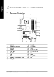
English You can use audio software to configure 2-/4-/5.1-/7.1-channel audio functioning. 1-7 Connectors Introduction 13 5 2 6 8 13 12 9 7 19 18 4 17 16 15 14 10 11 1) ATX_12V 2) ATX (Power Connector) 3) CPU_FAN 4) SYS_FAN 5) PWR_FAN 6) NB_FAN 7) FDD 8) IDE 9) S_ATA1/S_ATA2/S_ATA3/S_ATA4 10) PWR_LED 11) F_PANEL 12) AZALIA_FP 13) CD_IN 14) F_USB1 / F_USB2 15) F1_1394 / F2_1394 16) IR 17) COMA 18) CLR_CMOS 19) BAT GA-8I915G Pro Motherboard - 18 -
English You can use audio software to configure 2-/4-/5.1-/7.1-channel audio functioning. 1-7 Connectors Introduction 13 5 2 6 8 13 12 9 7 19 18 4 17 16 15 14 10 11 1) ATX_12V 2) ATX (Power Connector) 3) CPU_FAN 4) SYS_FAN 5) PWR_FAN 6) NB_FAN 7) FDD 8) IDE 9) S_ATA1/S_ATA2/S_ATA3/S_ATA4 10) PWR_LED 11) F_PANEL 12) AZALIA_FP 13) CD_IN 14) F_USB1 / F_USB2 15) F1_1394 / F2_1394 16) IR 17) COMA 18) CLR_CMOS 19) BAT GA-8I915G Pro Motherboard - 18 -

Manual
Page 19
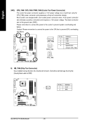
..., the system will not start . It is recommended that a power supply that is used (300W or greater). Caution! Please remove the sticker on the motherboard before plugging in while theATX power supplier is unable to an unstable system or a system that all the components on the...be used that does not provide the required power, the result can lead to start . Align the power connector with its proper location on the motherboard. Ifa power supply is able to handle the system voltage requirements. Before connecting the power connector, please make sure that is 24 pins;
..., the system will not start . It is recommended that a power supply that is used (300W or greater). Caution! Please remove the sticker on the motherboard before plugging in while theATX power supplier is unable to an unstable system or a system that all the components on the...be used that does not provide the required power, the result can lead to start . Align the power connector with its proper location on the motherboard. Ifa power supply is able to handle the system voltage requirements. Before connecting the power connector, please make sure that is 24 pins;
Manual
Page 20
... and requires a +12V power voltage. Please remember to connect the power to the CPU fan to prevent system overheating and fa ilur e. Definition 1 1 +12V 2 GND GA-8I915G Pro Motherboard - 20 - The black connector wire is GND) Pin No. Sometimes will not work. Please remember to connect the power to the cooler to prevent CPU...
... and requires a +12V power voltage. Please remember to connect the power to the CPU fan to prevent system overheating and fa ilur e. Definition 1 1 +12V 2 GND GA-8I915G Pro Motherboard - 20 - The black connector wire is GND) Pin No. Sometimes will not work. Please remember to connect the power to the cooler to prevent CPU...

Manual
Page 22
Pin No. It will blink when the system enters suspend mode. English 9) S_ATA1/S_ATA2/S_ATA3/S_ATA4(SerialATA Connector,Controlled by ICH 6) Pin No. 1 2 3 4 5 6 7 Definition GND TXP TXN GND RXN RXP GND 10) PWR_LED PWR_LED is connect with the system power indicator to work properly. 7 1 S_ATA (Control by ICH6) Serial ATA can provide 150M B/s transfer r ate. Please refer to the BIOS setting for the Serial ATA and install the proper driver in order to indicate whether the system is on/off. Definition 1 MPD+ 1 2 MPD- 3 MPD- GA-8I915G Pro Motherboard - 22 -
Pin No. It will blink when the system enters suspend mode. English 9) S_ATA1/S_ATA2/S_ATA3/S_ATA4(SerialATA Connector,Controlled by ICH 6) Pin No. 1 2 3 4 5 6 7 Definition GND TXP TXN GND RXN RXP GND 10) PWR_LED PWR_LED is connect with the system power indicator to work properly. 7 1 S_ATA (Control by ICH6) Serial ATA can provide 150M B/s transfer r ate. Please refer to the BIOS setting for the Serial ATA and install the proper driver in order to indicate whether the system is on/off. Definition 1 MPD+ 1 2 MPD- 3 MPD- GA-8I915G Pro Motherboard - 22 -
Manual
Page 24
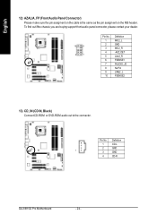
English 12) AZALIA_FP (FrontAudio Panel Connector) Please m ake sure the pin assigm ent on the cable is the sam e as the pin assigm ent on the M B header. Definition 1 CD-L 2 GND 1 3 GND 4 CD-R GA-8I915G Pro Motherboard - 24 - Pin No. To find out ifthe chassis you are buying support front audio panel connector, please contact your dealer. 10 9 2 1 Pin No. 1 2 3 4 5 6 7 8 9 10 Definition MIC2_L GND MIC2_R -ACZ_DET Line2_R FSENSE1 FAUOIO_JD No Pin LINE2_L FSENSE2 13) CD_IN (CD IN, Black) Connect CD-ROM or DVD-ROM audio out to the connector.
English 12) AZALIA_FP (FrontAudio Panel Connector) Please m ake sure the pin assigm ent on the cable is the sam e as the pin assigm ent on the M B header. Definition 1 CD-L 2 GND 1 3 GND 4 CD-R GA-8I915G Pro Motherboard - 24 - Pin No. To find out ifthe chassis you are buying support front audio panel connector, please contact your dealer. 10 9 2 1 Pin No. 1 2 3 4 5 6 7 8 9 10 Definition MIC2_L GND MIC2_R -ACZ_DET Line2_R FSENSE1 FAUOIO_JD No Pin LINE2_L FSENSE2 13) CD_IN (CD IN, Black) Connect CD-ROM or DVD-ROM audio out to the connector.
Manual
Page 26
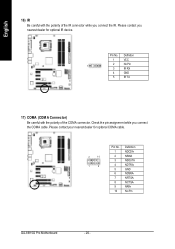
Pin No. Check the pin assignment while you nearest dealer for optional COMA cable. 2 10 1 9 Pin No. 1 2 3 4 5 6 7 8 9 10 Definition NDCDANSINA NSOUTA NDTRAGND NDSRANRT SANCT SANRIANo Pin GA-8I915G Pro Motherboard - 26 - Please contact your nearest dealer for optional IR device. English 16) IR Be careful with the polarity of the IR connector while you connect the IR. Please contact you connect the COMA cable. Definition 1 VCC 1 2 No Pin 3 IR RX 4 GND 5 IR TX 17) COMA (COM A Connector) Be careful with the polarity of the COMA connector.
Pin No. Check the pin assignment while you nearest dealer for optional COMA cable. 2 10 1 9 Pin No. 1 2 3 4 5 6 7 8 9 10 Definition NDCDANSINA NSOUTA NDTRAGND NDSRANRT SANCT SANRIANo Pin GA-8I915G Pro Motherboard - 26 - Please contact your nearest dealer for optional IR device. English 16) IR Be careful with the polarity of the IR connector while you connect the IR. Please contact you connect the COMA cable. Definition 1 VCC 1 2 No Pin 3 IR RX 4 GND 5 IR TX 17) COMA (COM A Connector) Be careful with the polarity of the COMA connector.
Manual
Page 28
English GA-8I915G Pro Motherboard - 28 -
English GA-8I915G Pro Motherboard - 28 -

Manual
Page 29
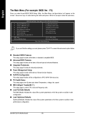
... sav e the current BIOS to a disk in the CMOS SRAM of the highlighted setup function is turned off, the battery on -line description of the motherboard. Ex it the Help Window press . - 29 - To ex it current page and return to the CMOS SETUP screen. BIOS Setup You can be reset... to be used. Status Page Setup Menu / Option P age Setup Menu Press F1 to pop up BIOS for Main Menu Mai n Menu The on the motherboard supplies the necessary pow er to select item Select Item Main Menu -
... sav e the current BIOS to a disk in the CMOS SRAM of the highlighted setup function is turned off, the battery on -line description of the motherboard. Ex it the Help Window press . - 29 - To ex it current page and return to the CMOS SETUP screen. BIOS Setup You can be reset... to be used. Status Page Setup Menu / Option P age Setup Menu Press F1 to pop up BIOS for Main Menu Mai n Menu The on the motherboard supplies the necessary pow er to select item Select Item Main Menu -
Manual
Page 30
... Manag ementSetup } PnP/PCIConfigur ations } PCH ealth Status } MB In telligent Tweaker(M. n PC Health Status This setup page is control CPU clock and frequency ratio. GA-8I915G Pro Motherboard - 30 - Flash Load Fail-Safe Defaults Load Optimized Defaults SetSu pervisor Pa ssword SetUser Password Save & Exit Setup Exit Without Saving higf:Selec t Item F10...
... Manag ementSetup } PnP/PCIConfigur ations } PCH ealth Status } MB In telligent Tweaker(M. n PC Health Status This setup page is control CPU clock and frequency ratio. GA-8I915G Pro Motherboard - 30 - Flash Load Fail-Safe Defaults Load Optimized Defaults SetSu pervisor Pa ssword SetUser Password Save & Exit Setup Exit Without Saving higf:Selec t Item F10...

Manual
Page 32
... for faster sy stem start up. Jan. to Sa t. Day The day , from 1 to 31(or the max imum allow for automatic dev ice detection. GA-8I915G Pro Motherboard - 32 - English 2-1 Standard CMOS Features Date(mm:dd:y y ) Tim e (hh:m m :ss) CMOS Setup Utility -Cop y right (C) 198 4-2004 Award Software Stan dard CM OS Features...
... for faster sy stem start up. Jan. to Sa t. Day The day , from 1 to 31(or the max imum allow for automatic dev ice detection. GA-8I915G Pro Motherboard - 32 - English 2-1 Standard CMOS Features Date(mm:dd:y y ) Tim e (hh:m m :ss) CMOS Setup Utility -Cop y right (C) 198 4-2004 Award Software Stan dard CM OS Features...

Manual
Page 33
Drive B is ty pically 512K for sy stems w ith 512K memory installed on the motherboard, or 640K for sy stems w ith 640K or more memory installed on The category determines w hether the computer w ill stop for all other errors. This ...
Drive B is ty pically 512K for sy stems w ith 512K memory installed on the motherboard, or 640K for sy stems w ith 640K or more memory installed on The category determines w hether the computer w ill stop for all other errors. This ...


