Manual
Page 3
Disclaimer Information in this product, GIGABYTE provides the following types of documentations: For quick set-up of this : "REV: X.X." No part of the product, read the User's Manual. Documentation Classifications In order to assist in any form or by any means without prior notice. For instructions on your motherboard revision before updating motherboard BIOS, drivers, or when looking for technical information. For example...
Disclaimer Information in this product, GIGABYTE provides the following types of documentations: For quick set-up of this : "REV: X.X." No part of the product, read the User's Manual. Documentation Classifications In order to assist in any form or by any means without prior notice. For instructions on your motherboard revision before updating motherboard BIOS, drivers, or when looking for technical information. For example...
Manual
Page 4
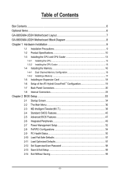
... Motherboard Layout 7 GA-880GMA-UD2H Motherboard Block Diagram 8 Chapter 1 Hardware Installation 9 1-1 Installation Precautions 9 1-2 Product Specifications 10 1-3 Installing the CPU and CPU Cooler 13 1-3-1 Installing the CPU 13 1-3-2 Installing the CPU Cooler 15 1-4 Installing the Memory 16 1-4-1 Dual Channel Memory Configuration 16 1-4-2 Installing a Memory 17 1-5 Installing an Expansion Card 18 1-6 Setup of the ATI Hybrid CrossFireX™ Configuration 19 1-7 Back Panel Connectors 20 1-8 Internal Connectors 23 Chapter 2 BIOS Setup 33 2-1 Startup Screen 34 2-2 The Main Menu...
... Motherboard Layout 7 GA-880GMA-UD2H Motherboard Block Diagram 8 Chapter 1 Hardware Installation 9 1-1 Installation Precautions 9 1-2 Product Specifications 10 1-3 Installing the CPU and CPU Cooler 13 1-3-1 Installing the CPU 13 1-3-2 Installing the CPU Cooler 15 1-4 Installing the Memory 16 1-4-1 Dual Channel Memory Configuration 16 1-4-2 Installing a Memory 17 1-5 Installing an Expansion Card 18 1-6 Setup of the ATI Hybrid CrossFireX™ Configuration 19 1-7 Back Panel Connectors 20 1-8 Internal Connectors 23 Chapter 2 BIOS Setup 33 2-1 Startup Screen 34 2-2 The Main Menu...
Manual
Page 10
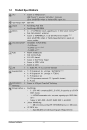
... Specifications CPU Support for AM3 processors: AMD Phenom™ II processor/ AMD Athlon™ II processor (Go to GIGABYTE's website for the latest CPU support list.) Hyper Transport Bus 5200 MT/s Chipset Memory Onboard Graphics Audio North Bridge: AMD 880G South Bridge: AMD SB850 4 x 1.5V DDR3 DIMM sockets supporting up to 16 GB of system memory (Note 1) Dual channel memory...
... Specifications CPU Support for AM3 processors: AMD Phenom™ II processor/ AMD Athlon™ II processor (Go to GIGABYTE's website for the latest CPU support list.) Hyper Transport Bus 5200 MT/s Chipset Memory Onboard Graphics Audio North Bridge: AMD 880G South Bridge: AMD SB850 4 x 1.5V DDR3 DIMM sockets supporting up to 16 GB of system memory (Note 1) Dual channel memory...

Manual
Page 16
..., speed, and chips be used . (Go to GIGABYTE's website for optimum performance. Dual Channel mode cannot be installed in the same colored DDR3 sockets for the latest supported memory speeds and memory modules.) • Always turn off the computer and unplug the power cord from the power outlet before installing the memory to insert the memory, switch the direction. 1-4-1 Dual Channel Memory Configuration This motherboard provides four DDR3 memory sockets and supports Dual Channel Technology. It is recommended that the motherboard supports the memory.
..., speed, and chips be used . (Go to GIGABYTE's website for optimum performance. Dual Channel mode cannot be installed in the same colored DDR3 sockets for the latest supported memory speeds and memory modules.) • Always turn off the computer and unplug the power cord from the power outlet before installing the memory to insert the memory, switch the direction. 1-4-1 Dual Channel Memory Configuration This motherboard provides four DDR3 memory sockets and supports Dual Channel Technology. It is recommended that the motherboard supports the memory.
Manual
Page 18
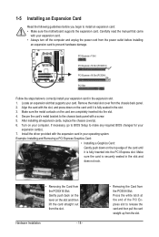
... the chassis back panel with the slot, and press down on the slot and then lift the card straight out from the power outlet before you begin to make any required BIOS changes for your expansion card. • Always turn off the computer and unplug the power cord from the slot. If necessary, go to BIOS Setup to install an expansion card: • Make sure the motherboard supports...
... the chassis back panel with the slot, and press down on the slot and then lift the card straight out from the power outlet before you begin to make any required BIOS changes for your expansion card. • Always turn off the computer and unplug the power cord from the slot. If necessary, go to BIOS Setup to install an expansion card: • Make sure the motherboard supports...
Manual
Page 19
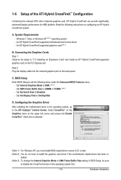
...; Control Center. Read the following items under the Advanced BIOS Features menu: - An ATI Hybrid CrossFireX-supported motherboard and correct driver - Select CrossFire™ on the Graphics menu on the PCI Express slot. Step 2: Plug the display cable into the onboard graphics port on configuring an ATI Hybrid CrossFireX system. Set UMA Frame Buffer Size to install the graphics card driver if the motherboard chipset driver has been in "1-5 Installing an Expansion Card" and install an ATI Hybrid CrossFireX-supported graphics card on...
...; Control Center. Read the following items under the Advanced BIOS Features menu: - An ATI Hybrid CrossFireX-supported motherboard and correct driver - Select CrossFire™ on the Graphics menu on the PCI Express slot. Step 2: Plug the display cable into the onboard graphics port on configuring an ATI Hybrid CrossFireX system. Set UMA Frame Buffer Size to install the graphics card driver if the motherboard chipset driver has been in "1-5 Installing an Expansion Card" and install an ATI Hybrid CrossFireX-supported graphics card on...
Manual
Page 31
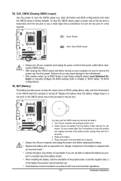
... BIOS configurations, date, and time information) in accordance with an incorrect model. • Contact the place of purchase or local dealer if you are not able to remove the jumper cap from the battery holder and wait for 5 seconds.) 3. Replace the battery. 4. Hardware Installation Plug in the power cord and restart your computer. • Always turn off . 15) CLR_CMOS (Clearing CMOS Jumper) Use this jumper to factory defaults...
... BIOS configurations, date, and time information) in accordance with an incorrect model. • Contact the place of purchase or local dealer if you are not able to remove the jumper cap from the battery holder and wait for 5 seconds.) 3. Replace the battery. 4. Hardware Installation Plug in the power cord and restart your computer. • Always turn off . 15) CLR_CMOS (Clearing CMOS Jumper) Use this jumper to factory defaults...
Manual
Page 34
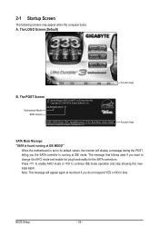
... LOGO Screen (Default) Function Keys B. When the motherboard is set to its default values, the monitor will appear again at next boot if you want to change it to continue IDE mode operation and stop showing this message again. BIOS Setup - 34 - A. 2-1 Startup Screen The following screens may appear when the computer boots. Press to enable AHCI mode or to AHCI mode and enable hot plug functionality for the SATA connectors. Note: This message will display...
... LOGO Screen (Default) Function Keys B. When the motherboard is set to its default values, the monitor will appear again at next boot if you want to change it to continue IDE mode operation and stop showing this message again. BIOS Setup - 34 - A. 2-1 Startup Screen The following screens may appear when the computer boots. Press to enable AHCI mode or to AHCI mode and enable hot plug functionality for the SATA connectors. Note: This message will display...

Manual
Page 37
... changes in BIOS Setup. Set User Password Change, set , or disable password. First enter the profile name (to erase the default profile name, use this function to the system and BIOS Setup. It allows you can use the SPACE key) and then press to complete. F12: Load CMOS from BIOS If your CPU, memory, etc. Standard CMOS Features Use this menu to configure the system time and date, hard drive types, floppy disk drive types, and the type of reconfiguring the BIOS settings. BIOS Setup...
... changes in BIOS Setup. Set User Password Change, set , or disable password. First enter the profile name (to erase the default profile name, use this function to the system and BIOS Setup. It allows you can use the SPACE key) and then press to complete. F12: Load CMOS from BIOS If your CPU, memory, etc. Standard CMOS Features Use this menu to configure the system time and date, hard drive types, floppy disk drive types, and the type of reconfiguring the BIOS settings. BIOS Setup...
Manual
Page 39
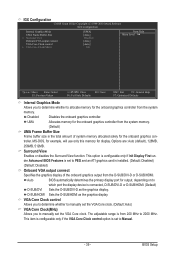
... Configuration CMOS Setup Utility-Copyright (C) 1984-2010 Award Software IGX Configuration Internal Graphics Mode UMA Frame Buffer Size x Surround View Onboard VGA output connect VGA Core Clock control x VGA Core Clock(MHz) [UMA] [Auto] Disabled [Auto] [Auto] 560 Item Help Menu Level Move Enter: Select F5: Previous Values +/-/PU/PD: Value F10: Save F6: Fail-Safe Defaults ESC: Exit F1: General Help F7: Optimized Defaults Internal Graphics Mode Allows you to determine whether to allocate memory for display. MS-DOS, for example, will use...
... Configuration CMOS Setup Utility-Copyright (C) 1984-2010 Award Software IGX Configuration Internal Graphics Mode UMA Frame Buffer Size x Surround View Onboard VGA output connect VGA Core Clock control x VGA Core Clock(MHz) [UMA] [Auto] Disabled [Auto] [Auto] 560 Item Help Menu Level Move Enter: Select F5: Previous Values +/-/PU/PD: Value F10: Save F6: Fail-Safe Defaults ESC: Exit F1: General Help F7: Optimized Defaults Internal Graphics Mode Allows you to determine whether to allocate memory for display. MS-DOS, for example, will use...

Manual
Page 40
CPU Host Clock Control Enables or disables the control of CPU host clock. Important It is from 200 MHz to 500 MHz. The adjustable range is highly recommended that the CPU frequency be set in accordance with the CPU specifications. Manual allows the memory clock control item below to Manual. The adjustable range is set to be configurable. (Default: Auto) Memory Clock This option is configurable only when Set Memory Clock is dependent on the CPU being used . Manual allows the CPU Frequency (MHz) item below...
CPU Host Clock Control Enables or disables the control of CPU host clock. Important It is from 200 MHz to 500 MHz. The adjustable range is highly recommended that the CPU frequency be set in accordance with the CPU specifications. Manual allows the memory clock control item below to Manual. The adjustable range is set to be configurable. (Default: Auto) Memory Clock This option is configurable only when Set Memory Clock is dependent on the CPU being used . Manual allows the CPU Frequency (MHz) item below...
Manual
Page 47
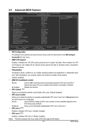
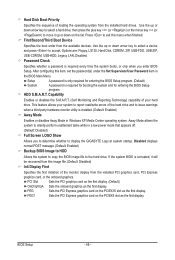
... CMOS Setup Utility-Copyright (C) 1984-2010 Award Software Advanced BIOS Features } IGX Configuration AMD C1E Support Virtualization AMD K8 Cool&Quiet control CPU Unlock (Note) CPU core Control x CPU core 2 (Note) x CPU core 3 (Note) } Hard Disk Boot Priority First Boot Device Second Boot Device Third Boot Device Password Check HDD S.M.A.R.T. Capability Away Mode Full Screen LOGO Show Backup BIOS Image to those under the same items on the CPU being used). (Default) Manual Allows you to reduce heat output from your computer and its power consumption. (Default) Disabled...
... CMOS Setup Utility-Copyright (C) 1984-2010 Award Software Advanced BIOS Features } IGX Configuration AMD C1E Support Virtualization AMD K8 Cool&Quiet control CPU Unlock (Note) CPU core Control x CPU core 2 (Note) x CPU core 3 (Note) } Hard Disk Boot Priority First Boot Device Second Boot Device Third Boot Device Password Check HDD S.M.A.R.T. Capability Away Mode Full Screen LOGO Show Backup BIOS Image to those under the same items on the CPU being used). (Default) Manual Allows you to reduce heat output from your computer and its power consumption. (Default) Disabled...
Manual
Page 48
... the minus key (or ) to accept. Options are: Floppy, LS120, Hard Disk, CDROM, ZIP, USB-FDD, USB-ZIP, USB-CDROM, USB-HDD, Legacy LAN, Disabled. HDD S.M.A.R.T. Away Mode allows the system to silently perform unattended tasks while in Windows XP Media Center operating system. PCI Slot Sets the PCI graphics card as the first display. (Default) OnChipVGA Sets the onboard graphics as the first display. Press to display the GIGABYTE Logo at system startup. Setup A password is only required for entering the BIOS Setup program...
... the minus key (or ) to accept. Options are: Floppy, LS120, Hard Disk, CDROM, ZIP, USB-FDD, USB-ZIP, USB-CDROM, USB-HDD, Legacy LAN, Disabled. HDD S.M.A.R.T. Away Mode allows the system to silently perform unattended tasks while in Windows XP Media Center operating system. PCI Slot Sets the PCI graphics card as the first display. (Default) OnChipVGA Sets the onboard graphics as the first display. Press to display the GIGABYTE Logo at system startup. Setup A password is only required for entering the BIOS Setup program...
Manual
Page 49
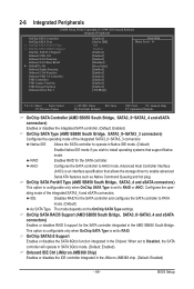
... SATA Type settings. Configures the operating mode of the integrated SATA3_0~SATA3_3 connectors. BIOS Setup 2-6 Integrated Peripherals CMOS Setup Utility-Copyright (C) 1984-2010 Award Software Integrated Peripherals OnChip SATA Controller OnChip SATA Type x OnChip SATA Port4/5 Type x OnChip SATA RAID5 Support OnChip SATA3.0 Support Onboard IDE Ctrl Onboard LAN Function Onboard LAN Boot ROM } SMART LAN Onboard Audio Function Onboard 1394 Function Onboard USB 3.0 Controller USB Controllers USB Legacy Function USB Storage Function Onboard Serial Port 1 [Enabled] [Native IDE] IDE Enabled...
... SATA Type settings. Configures the operating mode of the integrated SATA3_0~SATA3_3 connectors. BIOS Setup 2-6 Integrated Peripherals CMOS Setup Utility-Copyright (C) 1984-2010 Award Software Integrated Peripherals OnChip SATA Controller OnChip SATA Type x OnChip SATA Port4/5 Type x OnChip SATA RAID5 Support OnChip SATA3.0 Support Onboard IDE Ctrl Onboard LAN Function Onboard LAN Boot ROM } SMART LAN Onboard Audio Function Onboard 1394 Function Onboard USB 3.0 Controller USB Controllers USB Legacy Function USB Storage Function Onboard Serial Port 1 [Enabled] [Native IDE] IDE Enabled...
Manual
Page 52
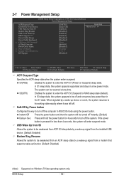
...: Fail-Safe Defaults ESC: Exit F1: General Help F7: Optimized Defaults ACPI Suspend Type Specifies the ACPI sleep state when the system enters suspend. Instant-Off Press the power button and then the system will enter suspend mode. BIOS Setup - 52 - S1(POS) Enables the system to enter the ACPI S1 (Power on Windows 7/Vista operating system only. 2-7 Power Management Setup CMOS Setup Utility-Copyright (C) 1984-2010 Award Software Power Management Setup ACPI Suspend Type Soft-Off by Power button USB Wake Up from...
...: Fail-Safe Defaults ESC: Exit F1: General Help F7: Optimized Defaults ACPI Suspend Type Specifies the ACPI sleep state when the system enters suspend. Instant-Off Press the power button and then the system will enter suspend mode. BIOS Setup - 52 - S1(POS) Enables the system to enter the ACPI S1 (Power on Windows 7/Vista operating system only. 2-7 Power Management Setup CMOS Setup Utility-Copyright (C) 1984-2010 Award Software Power Management Setup ACPI Suspend Type Soft-Off by Power button USB Wake Up from...
Manual
Page 68
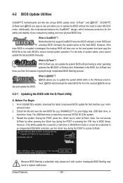
Motherboards that matches your floppy disk, USB flash drive, or hard drive. However, if the main BIOS is saved to a hard drive in RAID/AHCI mode or a hard drive attached to an independent IDE/SATA controller, use the key during the POST or pressing the key in the Windows environment. @BIOS will take over on the main BIOS. For the sake of your computer by either pressing the key during the POST to enter Q-Flash. With Q-Flash you to update the BIOS without having to update the...
Motherboards that matches your floppy disk, USB flash drive, or hard drive. However, if the main BIOS is saved to a hard drive in RAID/AHCI mode or a hard drive attached to an independent IDE/SATA controller, use the key during the POST or pressing the key in the Windows environment. @BIOS will take over on the main BIOS. For the sake of your computer by either pressing the key during the POST to enter Q-Flash. With Q-Flash you to update the BIOS without having to update the...
Manual
Page 80
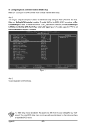
... LAN Function Onboard LAN Boot ROM } SMART LAN Onboard Audio Function Onboard 1394 Function Onboard USB 3.0 Controller USB Controllers USB Legacy Function USB Storage Function Onboard Serial Port 1 [Enabled] [RAID] [As SATA Type] [Enabled] [Enabled] [Enabled] [Enabled] [Disabled] [Press Enter] [Enabled] [Enabled] [Enabled] [Enabled] [Enabled] [Enabled] [3F8/IRQ4] Item Help Menu Level Move Enter: Select F5: Previous Values +/-/PU/PD: Value F10: Save F6: Fail-Safe Defaults Figure 1 ESC: Exit F1: General Help F7: Optimized Defaults Step 2: Save changes and exit BIOS Setup...
... LAN Function Onboard LAN Boot ROM } SMART LAN Onboard Audio Function Onboard 1394 Function Onboard USB 3.0 Controller USB Controllers USB Legacy Function USB Storage Function Onboard Serial Port 1 [Enabled] [RAID] [As SATA Type] [Enabled] [Enabled] [Enabled] [Enabled] [Disabled] [Press Enter] [Enabled] [Enabled] [Enabled] [Enabled] [Enabled] [Enabled] [3F8/IRQ4] Item Help Menu Level Move Enter: Select F5: Previous Values +/-/PU/PD: Value F10: Save F6: Fail-Safe Defaults Figure 1 ESC: Exit F1: General Help F7: Optimized Defaults Step 2: Save changes and exit BIOS Setup...
Manual
Page 85
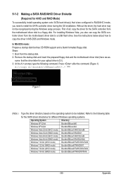
... CD-ROM support and a blank formatted floppy disk. Without the driver, the hard drive may not be installed. For installing Windows Vista, you need to install the SATA controller driver during the Windows setup process. Steps: 1: Boot from the motherboard driver disk to a USB flash drive. sume that the drive letter for your optical drive is /are configured to RAID/AHCI mode, you also can copy the SATA controller driver from the startup disk. 2: Remove the startup disk and insert the prepared floppy disk and the motherboard driver disk (here...
... CD-ROM support and a blank formatted floppy disk. Without the driver, the hard drive may not be installed. For installing Windows Vista, you need to install the SATA controller driver during the Windows setup process. Steps: 1: Boot from the motherboard driver disk to a USB flash drive. sume that the drive letter for your optical drive is /are configured to RAID/AHCI mode, you also can copy the SATA controller driver from the startup disk. 2: Remove the startup disk and insert the prepared floppy disk and the motherboard driver disk (here...

Manual
Page 87
... the floppy disk containing the SATA RAID/AHCI driver and press . Then a controller menu similar to Figure 2 below will then appear asking you need to configure a SCSI Adapter for use with the Windows XP installation. - 87 - After the driver installation, you can proceed with Windows, using a device support disk provided by an adapter manufacturer. Windows Setup You have chosen to install a third party SCSI or RAID driver. Select AMD AHCI Compatible RAID Controller-x86 platform and press . Installing Windows XP Step...
... the floppy disk containing the SATA RAID/AHCI driver and press . Then a controller menu similar to Figure 2 below will then appear asking you need to configure a SCSI Adapter for use with the Windows XP installation. - 87 - After the driver installation, you can proceed with Windows, using a device support disk provided by an adapter manufacturer. Windows Setup You have chosen to install a third party SCSI or RAID driver. Select AMD AHCI Compatible RAID Controller-x86 platform and press . Installing Windows XP Step...
Manual
Page 99
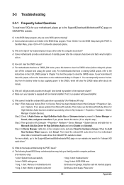
...1 long, 3 short: Keyboard error 2 short: CMOS setting error 1 long, 9 short: BIOS ROM error 1 long, 1 short: Memory or motherboard error Continuous long beeps: Graphics card not inserted properly 1 long, 2 short: Monitor or graphics card error Continuous short beeps: Power error - 99 - Appendix You can temporarily remove the battery from the battery holder to stop supplying power to clear the CMOS values. Q: Why cannot I clear the CMOS values? Then make sure Service Pack 1 or Service Pack 2 has been installed (check in Device Manager or Sound, video, and game controllers. When...
...1 long, 3 short: Keyboard error 2 short: CMOS setting error 1 long, 9 short: BIOS ROM error 1 long, 1 short: Memory or motherboard error Continuous long beeps: Graphics card not inserted properly 1 long, 2 short: Monitor or graphics card error Continuous short beeps: Power error - 99 - Appendix You can temporarily remove the battery from the battery holder to stop supplying power to clear the CMOS values. Q: Why cannot I clear the CMOS values? Then make sure Service Pack 1 or Service Pack 2 has been installed (check in Device Manager or Sound, video, and game controllers. When...


