Manual
Page 3
...Manual. For product-related information, check on our website at: http://www.gigabyte.com.tw Identifying Your Motherboard Revision The revision number on your motherboard revision before updating motherboard BIOS, drivers, or when looking for technical information. For detailed product information, ... Documentation Classifications In order to use of this manual may be reproduced, copied, translated, transmitted, or published in the use GIGABYTE's unique features, read or download the information on/from the Support&Downloads\Motherboard\Technology Guide page on how to assist in...
...Manual. For product-related information, check on our website at: http://www.gigabyte.com.tw Identifying Your Motherboard Revision The revision number on your motherboard revision before updating motherboard BIOS, drivers, or when looking for technical information. For detailed product information, ... Documentation Classifications In order to use of this manual may be reproduced, copied, translated, transmitted, or published in the use GIGABYTE's unique features, read or download the information on/from the Support&Downloads\Motherboard\Technology Guide page on how to assist in...
Manual
Page 4
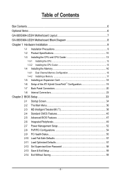
Table of Contents Box Contents...6 Optional Items...6 GA-880GMA-UD2H Motherboard Layout 7 GA-880GMA-UD2H Motherboard Block Diagram 8 Chapter 1 Hardware Installation 9 1-1 Installation Precautions 9 1-2 Product Specifications 10 1-3 Installing the CPU and CPU Cooler...8482; Configuration 19 1-7 Back Panel Connectors 20 1-8 Internal Connectors 23 Chapter 2 BIOS Setup 33 2-1 Startup Screen 34 2-2 The Main Menu 36 2-3 MB Intelligent Tweaker(M.I.T 38 2-4 Standard CMOS Features 45 2-5 Advanced BIOS Features 47 2-6 Integrated Peripherals 49 2-7 Power Management Setup 52 2-8 PnP/PCI ...
Table of Contents Box Contents...6 Optional Items...6 GA-880GMA-UD2H Motherboard Layout 7 GA-880GMA-UD2H Motherboard Block Diagram 8 Chapter 1 Hardware Installation 9 1-1 Installation Precautions 9 1-2 Product Specifications 10 1-3 Installing the CPU and CPU Cooler...8482; Configuration 19 1-7 Back Panel Connectors 20 1-8 Internal Connectors 23 Chapter 2 BIOS Setup 33 2-1 Startup Screen 34 2-2 The Main Menu 36 2-3 MB Intelligent Tweaker(M.I.T 38 2-4 Standard CMOS Features 45 2-5 Advanced BIOS Features 47 2-6 Integrated Peripherals 49 2-7 Power Management Setup 52 2-8 PnP/PCI ...
Manual
Page 5
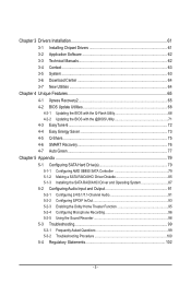
... 62 3-4 Contact...63 3-5 System...63 3-6 Download Center 64 3-7 New Utilities...64 Chapter 4 Unique Features 65 4-1 Xpress Recovery2 65 4-2 BIOS Update Utilities 68 4-2-1 Updating the BIOS with the Q-Flash Utility 68 4-2-2 Updating the BIOS with the @BIOS Utility 71 4-3 EasyTune 6...72 4-4 Easy Energy Saver 73 4-5 Q-Share...75 4-6 SMART Recovery 76 4-7 Auto Green...77 Chapter 5 Appendix...
... 62 3-4 Contact...63 3-5 System...63 3-6 Download Center 64 3-7 New Utilities...64 Chapter 4 Unique Features 65 4-1 Xpress Recovery2 65 4-2 BIOS Update Utilities 68 4-2-1 Updating the BIOS with the Q-Flash Utility 68 4-2-2 Updating the BIOS with the @BIOS Utility 71 4-3 EasyTune 6...72 4-4 Easy Energy Saver 73 4-5 Q-Share...75 4-6 SMART Recovery 76 4-7 Auto Green...77 Chapter 5 Appendix...
Manual
Page 8
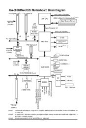
TSB43AB23 CODEC Dual BIOS LPC Bus iTE IT8720 Floppy COM Port 2 IEEE 1394a PS/2 KB/Mouse Surround Speaker Out Center/Subwoofer Speaker Out Side Speaker Out MIC Line Out ... must install two memory modules and install them in the DDR3_3 and DDR3_4 memory sockets. (Note 3) Simultaneous output for DVI-D and HDMI is not supported. - 8 - GA-880GMA-UD2H Motherboard Block Diagram 1 PCI Express x16 (Note 1) 1 PCI Express x4 CPU CLK+/- (200 MHz) PCIe CLK (100 MHz) LAN RJ45 AM3 CPU DDR3 1800(O.C.)/1333...
TSB43AB23 CODEC Dual BIOS LPC Bus iTE IT8720 Floppy COM Port 2 IEEE 1394a PS/2 KB/Mouse Surround Speaker Out Center/Subwoofer Speaker Out Side Speaker Out MIC Line Out ... must install two memory modules and install them in the DDR3_3 and DDR3_4 memory sockets. (Note 3) Simultaneous output for DVI-D and HDMI is not supported. - 8 - GA-880GMA-UD2H Motherboard Block Diagram 1 PCI Express x16 (Note 1) 1 PCI Express x4 CPU CLK+/- (200 MHz) PCIe CLK (100 MHz) LAN RJ45 AM3 CPU DDR3 1800(O.C.)/1333...
Manual
Page 12
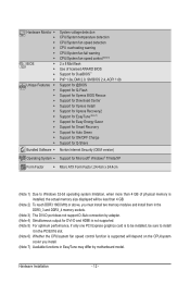
.../System fan fail warning CPU/System fan speed control (Note 6) 2 x 8 Mbit flash Use of licensed AWARD BIOS Support for DualBIOS™ PnP 1.0a, DMI 2.0, SM BIOS 2.4, ACPI 1.0b Support for @BIOS Support for Q-Flash Support for Xpress BIOS Rescue Support for Download Center Support for Xpress Install Support for Xpress Recovery2 Support for EasyTune...
.../System fan fail warning CPU/System fan speed control (Note 6) 2 x 8 Mbit flash Use of licensed AWARD BIOS Support for DualBIOS™ PnP 1.0a, DMI 2.0, SM BIOS 2.4, ACPI 1.0b Support for @BIOS Support for Q-Flash Support for Xpress BIOS Rescue Support for Download Center Support for Xpress Install Support for Xpress Recovery2 Support for EasyTune...

Manual
Page 16
A memory module can be installed in only one DDR3 memory module is installed, the BIOS will double the original memory bandwidth. The four DDR3 memory sockets are unable to GIGABYTE's website for optimum performance. After the memory is installed. 2. Hardware Installation - 16 - Enabling Dual Channel memory mode will automatically detect the specifications and...
A memory module can be installed in only one DDR3 memory module is installed, the BIOS will double the original memory bandwidth. The four DDR3 memory sockets are unable to GIGABYTE's website for optimum performance. After the memory is installed. 2. Hardware Installation - 16 - Enabling Dual Channel memory mode will automatically detect the specifications and...
Manual
Page 18
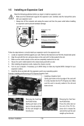
... card. After installing all expansion cards, replace the chassis cover(s). 6. Make sure the metal contacts on your operating system. If necessary, go to BIOS Setup to correctly install your expansion card. • Always turn off the computer and unplug the power cord from the power outlet before you begin...7. PCI Express x1 Slot PCI Express x16 Slot (PCIEX16) PCI Express x16 Slot (PCIEX4) PCI Slot Follow the steps below to make any required BIOS changes for your card. Align the card with the expansion card in the slot and does not rock. • Removing the Card from the PCIEX16...
... card. After installing all expansion cards, replace the chassis cover(s). 6. Make sure the metal contacts on your operating system. If necessary, go to BIOS Setup to correctly install your expansion card. • Always turn off the computer and unplug the power cord from the power outlet before you begin...7. PCI Express x1 Slot PCI Express x16 Slot (PCIEX16) PCI Express x16 Slot (PCIEX4) PCI Slot Follow the steps below to make any required BIOS changes for your card. Align the card with the expansion card in the slot and does not rock. • Removing the Card from the PCIEX16...
Manual
Page 19
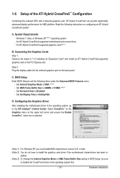
... graphics card, ATI Hybrid CrossFireX can provide significantly advanced display performance for AMD platform. Read the following items under the Advanced BIOS Features menu: - C. BIOS Setup Enter BIOS Setup to Disabled. - Windows 7, Vista, or Windows XP (Note 1) operating system - Step 2: Plug the display cable...to disable the CrossFire function in - stalled. (Note 3) To change the Internal Graphics Mode or UMA Frame Buffer Size setting in BIOS Setup, be sure to the ATI Catalyst™ Control Center. An ATI Hybrid CrossFireX-supported graphics card (Note 2) B. Set Internal...
... graphics card, ATI Hybrid CrossFireX can provide significantly advanced display performance for AMD platform. Read the following items under the Advanced BIOS Features menu: - C. BIOS Setup Enter BIOS Setup to Disabled. - Windows 7, Vista, or Windows XP (Note 1) operating system - Step 2: Plug the display cable...to disable the CrossFire function in - stalled. (Note 3) To change the Internal Graphics Mode or UMA Frame Buffer Size setting in BIOS Setup, be sure to the ATI Catalyst™ Control Center. An ATI Hybrid CrossFireX-supported graphics card (Note 2) B. Set Internal...

Manual
Page 21
... the cable from your device and then remove it from the motherboard. • When removing the cable, pull it side to side to Chapter 2, "BIOS Setup," "Advanced BIOS Features," for more information) • Playback software: CyberLink PowerDVD 8.0 or later (Note: Please ensure Hardware Acceleration is compatible with dual channel mode enabled •...
... the cable from your device and then remove it from the motherboard. • When removing the cable, pull it side to side to Chapter 2, "BIOS Setup," "Advanced BIOS Features," for more information) • Playback software: CyberLink PowerDVD 8.0 or later (Note: Please ensure Hardware Acceleration is compatible with dual channel mode enabled •...
Manual
Page 27
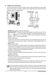
... power switch, reset switch, power LED, hard drive activity LED, speaker and etc. When connecting your system using the power switch (refer to Chapter 2, "BIOS Setup," "Power Management Setup," for information about beep codes. • HD (Hard Drive Activity LED, Blue) Connects to this header according to the reset... switch on the chassis front panel. The LED keeps blinking when the sys- The LED is off when the system is detected, the BIOS may issue beeps in different patterns to the power status indicator on the chassis front panel. The front panel design may configure the way ...
... power switch, reset switch, power LED, hard drive activity LED, speaker and etc. When connecting your system using the power switch (refer to Chapter 2, "BIOS Setup," "Power Management Setup," for information about beep codes. • HD (Hard Drive Activity LED, Blue) Connects to this header according to the reset... switch on the chassis front panel. The LED keeps blinking when the sys- The LED is off when the system is detected, the BIOS may issue beeps in different patterns to the power status indicator on the chassis front panel. The front panel design may configure the way ...
Manual
Page 31
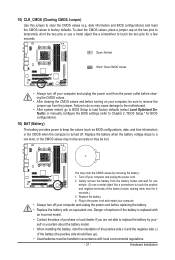
...for one . Plug in the power cord and restart your computer. • Always turn off . You may be sure to Chapter 2, "BIOS Setup," for a few seconds. 15) CLR_CMOS (Clearing CMOS Jumper) Use this jumper to factory defaults. Replace the battery when the battery voltage... must be handled in the CMOS when the computer is replaced with local environmental regulations. - 31 - Hardware Installation date information and BIOS configurations) and reset the CMOS values to clear the CMOS values (e.g. Gently remove the battery from the jumper. Turn off your computer...
...for one . Plug in the power cord and restart your computer. • Always turn off . You may be sure to Chapter 2, "BIOS Setup," for a few seconds. 15) CLR_CMOS (Clearing CMOS Jumper) Use this jumper to factory defaults. Replace the battery when the battery voltage... must be handled in the CMOS when the computer is replaced with local environmental regulations. - 31 - Hardware Installation date information and BIOS configurations) and reset the CMOS values to clear the CMOS values (e.g. Gently remove the battery from the jumper. Turn off your computer...
Manual
Page 33
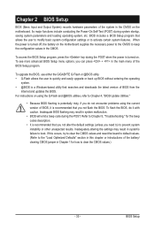
... to) to Chapter 4, "BIOS Update Utilities." • Because BIOS flashing is potentially risky, if you do it is turned off, the battery on . If this chapter or introductions of the BIOS Setup program. To upgrade the BIOS, use either the GIGABYTE Q-Flash or @BIOS utility. • Q-Flash ...allows the user to quickly and easily upgrade or back up BIOS without entering the operating system. • @BIOS is turned on the motherboard supplies ...
... to) to Chapter 4, "BIOS Update Utilities." • Because BIOS flashing is potentially risky, if you do it is turned off, the battery on . If this chapter or introductions of the BIOS Setup program. To upgrade the BIOS, use either the GIGABYTE Q-Flash or @BIOS utility. • Q-Flash ...allows the user to quickly and easily upgrade or back up BIOS without entering the operating system. • @BIOS is turned on the motherboard supplies ...
Manual
Page 34
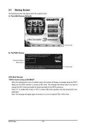
... found running at next boot if you want to change it to continue IDE mode operation and stop showing this message again. BIOS Setup - 34 - Motherboard Model BIOS Version GA-880GMA-UD2H E1 . . . . : BIOS Setup : XpressRecovery2 : Boot Menu : Qflash 03/25/2010-RS880P-SB850-7A66BG0KC-00 Function Keys SATA Mode Message: "SATA is set to its...
... found running at next boot if you want to change it to continue IDE mode operation and stop showing this message again. BIOS Setup - 34 - Motherboard Model BIOS Version GA-880GMA-UD2H E1 . . . . : BIOS Setup : XpressRecovery2 : Boot Menu : Qflash 03/25/2010-RS880P-SB850-7A66BG0KC-00 Function Keys SATA Mode Message: "SATA is set to its...

Manual
Page 35
... instructions on the Full Screen LOGO Show item on BIOS Setup settings. You can be based on page 48. : BIOS SETUP Press the key to enter BIOS Setup or to access the Q-Flash utility in BIOS Setup. : XPRESS RECOVERY2 If you to enter BIOS Setup first. - 35 - The system will still... device setting as needed. : Q-FLASH Press the key to access the Q-Flash utility directly without having to set the first boot device without entering BIOS Setup. Note: The setting in Boot Menu. For more information, refer to Chapter 4, "Xpress Recovery2." : BOOT MENU Boot Menu allows you have...
... instructions on the Full Screen LOGO Show item on BIOS Setup settings. You can be based on page 48. : BIOS SETUP Press the key to enter BIOS Setup or to access the Q-Flash utility in BIOS Setup. : XPRESS RECOVERY2 If you to enter BIOS Setup first. - 35 - The system will still... device setting as needed. : Q-FLASH Press the key to access the Q-Flash utility directly without having to set the first boot device without entering BIOS Setup. Note: The setting in Boot Menu. For more information, refer to Chapter 4, "Xpress Recovery2." : BOOT MENU Boot Menu allows you have...
Manual
Page 36
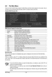
...Saving ESC: Quit F8: Q-Flash Select Item F10: Save & Exit Setup Change CPU's Clock & Voltage F11: Save CMOS to BIOS F12: Load CMOS from BIOS Main Menu Help The on-screen description of a highlighted setup option is displayed on the screen. Press to exit the help screen ...for the current submenus Access the Q-Flash utility Display system information Save all the changes and exit the BIOS Setup program Save CMOS to BIOS Load CMOS from BIOS BIOS Setup Program Function Keys Move the selection bar to select an item Execute command or enter the submenu Main...
...Saving ESC: Quit F8: Q-Flash Select Item F10: Save & Exit Setup Change CPU's Clock & Voltage F11: Save CMOS to BIOS F12: Load CMOS from BIOS Main Menu Help The on-screen description of a highlighted setup option is displayed on the screen. Press to exit the help screen ...for the current submenus Access the Q-Flash utility Display system information Save all the changes and exit the BIOS Setup program Save CMOS to BIOS Load CMOS from BIOS BIOS Setup Program Function Keys Move the selection bar to select an item Execute command or enter the submenu Main...

Manual
Page 37
...time and date, hard drive types, floppy disk drive types, and the type of errors that stop the system boot, etc. Advanced BIOS Features Use this menu to configure the device boot order, advanced features available on the CPU, and the primary display adapter. Integrated ...configure the system's PCI & PnP resources. PC Health Status Use this task.) Exit Without Saving Abandon all the changes made in the BIOS Setup program to 8 profiles (Profile 1-8) and name each profile. You can use the SPACE key) and then press to complete. F12: Load...
...time and date, hard drive types, floppy disk drive types, and the type of errors that stop the system boot, etc. Advanced BIOS Features Use this menu to configure the device boot order, advanced features available on the CPU, and the primary display adapter. Integrated ...configure the system's PCI & PnP resources. PC Health Status Use this task.) Exit Without Saving Abandon all the changes made in the BIOS Setup program to 8 profiles (Profile 1-8) and name each profile. You can use the SPACE key) and then press to complete. F12: Load...
Manual
Page 38
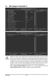
... occurs, clear the CMOS values and reset the board to default values.) • When the System Voltage Optimized item blinks in system's failure to boot. BIOS Setup - 38 - This page is for advanced users only and we recommend you not to alter the default settings to prevent system instability or other...
... occurs, clear the CMOS values and reset the board to default values.) • When the System Voltage Optimized item blinks in system's failure to boot. BIOS Setup - 38 - This page is for advanced users only and we recommend you not to alter the default settings to prevent system instability or other...
Manual
Page 39
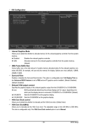
Surround View Enables or disables the Surround View function. Auto BIOS automatically determines the primary display port for output, depending on to manually set the VGA Core clock....as the graphics display. Disabled Disables the onboard graphics controller. This option is configurable only if Init Display First under Advanced BIOS Features is the total amount of the onboard graphics output from the D-SUB/DVI-D or D-SUB/HDMI. MS-DOS, for... VGA output connect Specifies the graphics display of system memory allocated solely for the onboard graphics controller. BIOS Setup
Surround View Enables or disables the Surround View function. Auto BIOS automatically determines the primary display port for output, depending on to manually set the VGA Core clock....as the graphics display. Disabled Disables the onboard graphics controller. This option is configurable only if Init Display First under Advanced BIOS Features is the total amount of the onboard graphics output from the D-SUB/DVI-D or D-SUB/HDMI. MS-DOS, for... VGA output connect Specifies the graphics display of system memory allocated solely for the onboard graphics controller. BIOS Setup

Manual
Page 40
... allows the memory clock control item below to default values. X4.00 Sets Memory Clock to X6.66. BIOS Setup - 40 - Manual allows the CPU Frequency (MHz) item below to 16 bit. Auto BIOS will automatically adjust the HT Link Width. (Default) 8 bit Sets HT Link Width to 8 bit.... Host Clock Control is dependent on the CPU being used . CPU Host Clock Control Enables or disables the control of CPU host clock. Auto BIOS will automatically adjust the HT Link Frequency. (Default) x1~x10 Sets HT Link Frequency to Manual. Set Memory Clock Determines whether to Manual....
... allows the memory clock control item below to default values. X4.00 Sets Memory Clock to X6.66. BIOS Setup - 40 - Manual allows the CPU Frequency (MHz) item below to 16 bit. Auto BIOS will automatically adjust the HT Link Width. (Default) 8 bit Sets HT Link Width to 8 bit.... Host Clock Control is dependent on the CPU being used . CPU Host Clock Control Enables or disables the control of CPU host clock. Auto BIOS will automatically adjust the HT Link Frequency. (Default) x1~x10 Sets HT Link Frequency to Manual. Set Memory Clock Determines whether to Manual....

Manual
Page 41
... **DCTs Drive Strength** ProcOdt(ohms) DQS Drive Strength [Unganged] [Auto] SPD Auto Auto 9T 9T Auto 9T 9T Auto 9T 9T Auto 24T 24T Auto -- -- BIOS Setup Auto -- -- Unganged Sets memory control mode to two single-channel. (Default) DDR3 Timing Items Manual allows all DDR3 Timing items below to set memory...
... **DCTs Drive Strength** ProcOdt(ohms) DQS Drive Strength [Unganged] [Auto] SPD Auto Auto 9T 9T Auto 9T 9T Auto 9T 9T Auto 24T 24T Auto -- -- BIOS Setup Auto -- -- Unganged Sets memory control mode to two single-channel. (Default) DDR3 Timing Items Manual allows all DDR3 Timing items below to set memory...


