Manual
Page 1
GA-880GMA-UD2H AM3 socket motherboard for AMD Phenom™ II processor/AMD Athlon™ II processor User's Manual Rev. 2002 12ME-880GA2H-2002R
GA-880GMA-UD2H AM3 socket motherboard for AMD Phenom™ II processor/AMD Athlon™ II processor User's Manual Rev. 2002 12ME-880GA2H-2002R
Manual
Page 2
Motherboard GA-880GMA-UD2H Apr. 12, 2010 Motherboard GA-880GMA-UD2H Apr. 12, 2010
Motherboard GA-880GMA-UD2H Apr. 12, 2010 Motherboard GA-880GMA-UD2H Apr. 12, 2010
Manual
Page 3
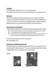
...drivers, or when looking for technical information. For instructions on how to their respective owners. All rights reserved. No part of GIGABYTE. Check your motherboard looks like this manual are legally registered to use of this manual is protected by copyright laws and is...: Copyright © 2010 GIGA-BYTE TECHNOLOGY CO., LTD. Changes to assist in this : "REV: X.X." The trademarks mentioned in the use GIGABYTE's unique features, read the User's Manual. For example, "REV: 1.0" means the revision of the product, read the Quick Installation Guide included...
...drivers, or when looking for technical information. For instructions on how to their respective owners. All rights reserved. No part of GIGABYTE. Check your motherboard looks like this manual are legally registered to use of this manual is protected by copyright laws and is...: Copyright © 2010 GIGA-BYTE TECHNOLOGY CO., LTD. Changes to assist in this : "REV: X.X." The trademarks mentioned in the use GIGABYTE's unique features, read the User's Manual. For example, "REV: 1.0" means the revision of the product, read the Quick Installation Guide included...
Manual
Page 4
Table of Contents Box Contents...6 Optional Items...6 GA-880GMA-UD2H Motherboard Layout 7 GA-880GMA-UD2H Motherboard Block Diagram 8 Chapter 1 Hardware Installation 9 1-1 Installation Precautions 9 1-2 Product Specifications 10 1-3 Installing the CPU and CPU Cooler 13 1-3-1 Installing the CPU 13 1-3-2 Installing the CPU ...
Table of Contents Box Contents...6 Optional Items...6 GA-880GMA-UD2H Motherboard Layout 7 GA-880GMA-UD2H Motherboard Block Diagram 8 Chapter 1 Hardware Installation 9 1-1 Installation Precautions 9 1-2 Product Specifications 10 1-3 Installing the CPU and CPU Cooler 13 1-3-1 Installing the CPU 13 1-3-2 Installing the CPU ...
Manual
Page 5
Chapter 3 Drivers Installation 61 3-1 Installing Chipset Drivers 61 3-2 Application Software 62 3-3 Technical Manuals 62 3-4 Contact...63 3-5 System...63 3-6 Download Center 64 3-7 New Utilities...64 Chapter 4 Unique Features 65 4-1 Xpress Recovery2 65 4-2 BIOS Update Utilities 68 4-2-1 Updating the BIOS with the Q-Flash Utility 68 4-2-2 Updating the BIOS with the @BIOS Utility 71 4-3 EasyTune 6...72 4-4 Easy Energy Saver 73 4-5 Q-Share...75 4-6 SMART Recovery 76 4-7 Auto Green...77 Chapter 5 Appendix...79 5-1 Configuring SATA Hard Drive(s 79 5-1-1 Configuring AMD SB850 SATA ...
Chapter 3 Drivers Installation 61 3-1 Installing Chipset Drivers 61 3-2 Application Software 62 3-3 Technical Manuals 62 3-4 Contact...63 3-5 System...63 3-6 Download Center 64 3-7 New Utilities...64 Chapter 4 Unique Features 65 4-1 Xpress Recovery2 65 4-2 BIOS Update Utilities 68 4-2-1 Updating the BIOS with the Q-Flash Utility 68 4-2-2 Updating the BIOS with the @BIOS Utility 71 4-3 EasyTune 6...72 4-4 Easy Energy Saver 73 4-5 Q-Share...75 4-6 SMART Recovery 76 4-7 Auto Green...77 Chapter 5 Appendix...79 5-1 Configuring SATA Hard Drive(s 79 5-1-1 Configuring AMD SB850 SATA ...
Manual
Page 6
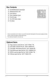
Box Contents GA-880GMA-UD2H motherboard Motherboard driver disk User's Manual Quick Installation Guide One IDE cable Two SATA 3Gb/s cables I/O Shield • The box contents above are subject to ...
Box Contents GA-880GMA-UD2H motherboard Motherboard driver disk User's Manual Quick Installation Guide One IDE cable Two SATA 3Gb/s cables I/O Shield • The box contents above are subject to ...
Manual
Page 7
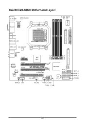
GA-880GMA-UD2H Motherboard Layout KB_MS_USB ATX_12V CPU_FAN VGA_DVI Socket AM3 M_BIOS B_BIOS ATX FDD iTE IT8720 HDMI_SPDIF ESATA_1394_USB USB30_LAN NEC D720200F1 F_AUDIO AUDIO PCIEX1 Realtek RTL8111D CD_IN CODEC PCIEX16 PCIEX4 PCI AMD 880G GA-880GMA-UD2H T.I. TSB43AB23 CLR_CMOS DDR3_1 DDR3_2 DDR3_3 DDR3_4 IDE AMD SB850 JMicron JMB368 SATA3_3 SATA3_1 BAT SPDIF_IO COM SYS_FAN F_1394 F_USB2 F_USB3 F_USB1 SATA3_4 SATA3_2 SATA3_0 F_PANEL - 7 -
GA-880GMA-UD2H Motherboard Layout KB_MS_USB ATX_12V CPU_FAN VGA_DVI Socket AM3 M_BIOS B_BIOS ATX FDD iTE IT8720 HDMI_SPDIF ESATA_1394_USB USB30_LAN NEC D720200F1 F_AUDIO AUDIO PCIEX1 Realtek RTL8111D CD_IN CODEC PCIEX16 PCIEX4 PCI AMD 880G GA-880GMA-UD2H T.I. TSB43AB23 CLR_CMOS DDR3_1 DDR3_2 DDR3_3 DDR3_4 IDE AMD SB850 JMicron JMB368 SATA3_3 SATA3_1 BAT SPDIF_IO COM SYS_FAN F_1394 F_USB2 F_USB3 F_USB1 SATA3_4 SATA3_2 SATA3_0 F_PANEL - 7 -
Manual
Page 8
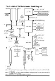
GA-880GMA-UD2H Motherboard Block Diagram 1 PCI Express x16 (Note 1) 1 PCI Express x4 CPU CLK+/- (200 MHz) PCIe CLK (100 MHz) LAN RJ45 AM3 CPU DDR3 1800(O.C.)/1333/...
GA-880GMA-UD2H Motherboard Block Diagram 1 PCI Express x16 (Note 1) 1 PCI Express x4 CPU CLK+/- (200 MHz) PCIe CLK (100 MHz) LAN RJ45 AM3 CPU DDR3 1800(O.C.)/1333/...
Manual
Page 9
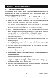
Chapter 1 Hardware Installation 1-1 Installation Precautions The motherboard contains numerous delicate electronic circuits and components which can lead to damage to system components as well as physical harm to the user. • If you do not have an ESD wrist strap, keep your hands dry and first touch a metal object to eliminate static electricity. • Prior to installing the motherboard, please have it on top of an antistatic pad or within an electrostatic shielding container. • Before unplugging the power supply cable from the power outlet before installing or removing the ...
Chapter 1 Hardware Installation 1-1 Installation Precautions The motherboard contains numerous delicate electronic circuits and components which can lead to damage to system components as well as physical harm to the user. • If you do not have an ESD wrist strap, keep your hands dry and first touch a metal object to eliminate static electricity. • Prior to installing the motherboard, please have it on top of an antistatic pad or within an electrostatic shielding container. • Before unplugging the power supply cable from the power outlet before installing or removing the ...
Manual
Page 10
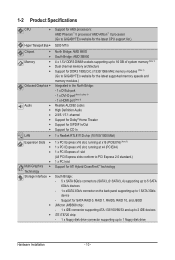
...device - 1-2 Product Specifications CPU Support for AM3 processors: AMD Phenom™ II processor/ AMD Athlon™ II processor (Go to GIGABYTE's website for the latest CPU support list.) Hyper Transport Bus 5200 MT/s Chipset Memory ... to 16 GB of system memory (Note 1) Dual channel memory architecture Support for DDR3 1800(O.C.)/1333/1066 MHz memory modules (Note 2) (Go to GIGABYTE's website for the latest supported memory speeds and memory modules.) Integrated in the North Bridge: - 1 x D-Sub port - 1 x DVI-D port...
...device - 1-2 Product Specifications CPU Support for AM3 processors: AMD Phenom™ II processor/ AMD Athlon™ II processor (Go to GIGABYTE's website for the latest CPU support list.) Hyper Transport Bus 5200 MT/s Chipset Memory ... to 16 GB of system memory (Note 1) Dual channel memory architecture Support for DDR3 1800(O.C.)/1333/1066 MHz memory modules (Note 2) (Go to GIGABYTE's website for the latest supported memory speeds and memory modules.) Integrated in the North Bridge: - 1 x D-Sub port - 1 x DVI-D port...
Manual
Page 11
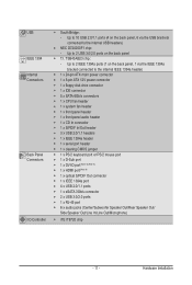
TSB43AB23 chip: - Up to 10 USB 2.0/1.1 ports (4 on the back panel, 1 via the USB brackets connected to the internal USB headers) NEC D720200F1 chip: - Up to 2 IEEE 1394a ports (1 on the back panel, 6 via the IEEE 1394a bracket connected to 2 USB 3.0/2.0 ports on the back panel IEEE 1394 T.I /O Controller w iTE IT8720 chip - 11 - USB South Bridge: - Hardware Installation Up to the internal IEEE 1394a header) Internal w 1 x 24-pin ATX main power connector Connectors w 1 x 8-pin ATX 12V power ...
TSB43AB23 chip: - Up to 10 USB 2.0/1.1 ports (4 on the back panel, 1 via the USB brackets connected to the internal USB headers) NEC D720200F1 chip: - Up to 2 IEEE 1394a ports (1 on the back panel, 6 via the IEEE 1394a bracket connected to 2 USB 3.0/2.0 ports on the back panel IEEE 1394 T.I /O Controller w iTE IT8720 chip - 11 - USB South Bridge: - Hardware Installation Up to the internal IEEE 1394a header) Internal w 1 x 24-pin ATX main power connector Connectors w 1 x 8-pin ATX 12V power ...
Manual
Page 12
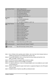
Hardware Monitor w w w w w w BIOS w w w w Unique Features w w w w w w w w w w w w Bundled Software w System voltage detection CPU/System temperature detection CPU/System fan speed detection CPU overheating warning CPU/System fan fail warning CPU/System fan speed control (Note 6) 2 x 8 Mbit flash Use of licensed AWARD BIOS Support for DualBIOS™ PnP 1.0a, DMI 2.0, SM BIOS 2.4, ACPI 1.0b Support for @BIOS Support for Q-Flash Support for Xpress BIOS Rescue Support for ...
Hardware Monitor w w w w w w BIOS w w w w Unique Features w w w w w w w w w w w w Bundled Software w System voltage detection CPU/System temperature detection CPU/System fan speed detection CPU overheating warning CPU/System fan fail warning CPU/System fan speed control (Note 6) 2 x 8 Mbit flash Use of licensed AWARD BIOS Support for DualBIOS™ PnP 1.0a, DMI 2.0, SM BIOS 2.4, ACPI 1.0b Support for @BIOS Support for Q-Flash Support for Xpress BIOS Rescue Support for ...
Manual
Page 13
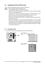
... and CPU Cooler Read the following guidelines before you begin to install the CPU: • Make sure that the motherboard supports the CPU. (Go to GIGABYTE's website for the peripherals. age of the CPU. It is not installed, otherwise overheating and dam- A Small Triangle Mark Denotes Pin One of the CPU...
... and CPU Cooler Read the following guidelines before you begin to install the CPU: • Make sure that the motherboard supports the CPU. (Go to GIGABYTE's website for the peripherals. age of the CPU. It is not installed, otherwise overheating and dam- A Small Triangle Mark Denotes Pin One of the CPU...
Manual
Page 14
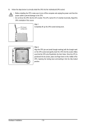
Adjust the CPU orientation if this occurs. Step 2: Align the CPU pin one finger down on the CPU socket and gently insert the CPU into the fully locked position. CPU Socket Locking Lever Step 1: Completely lift up the CPU socket locking lever. Make sure that the CPU pins fit perfectly into the CPU socket. The CPU cannot fit in if oriented incorrectly. Hardware Installation - 14 - Once the CPU is positioned into its socket, place one (small triangle marking) with the triangle mark on the middle of the CPU, lowering the locking lever and latching it into the socket. B....
Adjust the CPU orientation if this occurs. Step 2: Align the CPU pin one finger down on the CPU socket and gently insert the CPU into the fully locked position. CPU Socket Locking Lever Step 1: Completely lift up the CPU socket locking lever. Make sure that the CPU pins fit perfectly into the CPU socket. The CPU cannot fit in if oriented incorrectly. Hardware Installation - 14 - Once the CPU is positioned into its socket, place one (small triangle marking) with the triangle mark on the middle of the CPU, lowering the locking lever and latching it into the socket. B....
Manual
Page 15
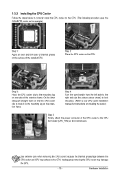
... grease on the motherboard. Inadequately removing the CPU cooler may adhere to correctly install the CPU cooler on the CPU. (The following procedure uses the GIGABYTE cooler as the picture above shows) to lock into place. (Refer to your CPU cooler installation manual for instructions on installing the cooler.) Step 5: Finally...
... grease on the motherboard. Inadequately removing the CPU cooler may adhere to correctly install the CPU cooler on the CPU. (The following procedure uses the GIGABYTE cooler as the picture above shows) to lock into place. (Refer to your CPU cooler installation manual for instructions on installing the cooler.) Step 5: Finally...

Manual
Page 16
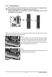
... installing the memory in only one DDR3 memory module is recommended that memory of the same capacity, brand, speed, and chips be used . (Go to GIGABYTE's website for optimum performance. After the memory is recommended that memory of the memory. It is installed, the BIOS will double the original memory bandwidth.
... installing the memory in only one DDR3 memory module is recommended that memory of the same capacity, brand, speed, and chips be used . (Go to GIGABYTE's website for optimum performance. After the memory is recommended that memory of the memory. It is installed, the BIOS will double the original memory bandwidth.
Manual
Page 17
DDR3 and DDR2 DIMMs are not compatible to each other or DDR DIMMs. Be sure to the memory module. As indicated in one direction. Hardware Installation 1-4-2 Installing a Memory Before installing a memory module, make sure to turn off the computer and unplug the power cord from the power outlet to prevent damage to install DDR3 DIMMs on this motherboard. Notch DDR3 DIMM A DDR3 memory module has a notch, so it vertically into place when the memory module is securely inserted. - 17 - Spread the retaining clips at both ends of the socket will snap into the memory socket. Step ...
DDR3 and DDR2 DIMMs are not compatible to each other or DDR DIMMs. Be sure to the memory module. As indicated in one direction. Hardware Installation 1-4-2 Installing a Memory Before installing a memory module, make sure to turn off the computer and unplug the power cord from the power outlet to prevent damage to install DDR3 DIMMs on this motherboard. Notch DDR3 DIMM A DDR3 memory module has a notch, so it vertically into place when the memory module is securely inserted. - 17 - Spread the retaining clips at both ends of the socket will snap into the memory socket. Step ...
Manual
Page 18
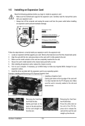
Align the card with the slot, and press down on the top edge of the PCI Express slot to the chassis back panel with a screw. 5. Hardware Installation - 18 - • Removing the Card from the slot. Secure the card's metal bracket to release the card and then pull the card straight up from the PCIEX4 Slot: Press the white latch at the end of the card until it is fully inserted into the slot. 4. If necessary, go to BIOS Setup to correctly install your expansion card(s). 7. Make sure the card is fully seated in the expansion slot. 1. PCI Express x1 Slot PCI Express x16...
Align the card with the slot, and press down on the top edge of the PCI Express slot to the chassis back panel with a screw. 5. Hardware Installation - 18 - • Removing the Card from the slot. Secure the card's metal bracket to release the card and then pull the card straight up from the PCIEX4 Slot: Press the white latch at the end of the card until it is fully inserted into the slot. 4. If necessary, go to BIOS Setup to correctly install your expansion card(s). 7. Make sure the card is fully seated in the expansion slot. 1. PCI Express x1 Slot PCI Express x16...
Manual
Page 19
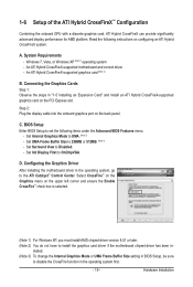
Read the following items under the Advanced BIOS Features menu: - Set Internal Graphics Mode to Disabled. - Set Surround View to UMA. (Note 3) - D. An ATI Hybrid CrossFireX-supported graphics card (Note 2) B. C. Set Init Display First to 256MB or 512MB. (Note 3) - Select CrossFire™ on the Graphics menu on the PCI Express slot. stalled. (Note 3) To change the Internal Graphics Mode or UMA Frame Buffer Size setting in BIOS Setup, be sure to install the graphics card driver if the motherboard chipset driver has been in the operating system first. - 19 - ...
Read the following items under the Advanced BIOS Features menu: - Set Internal Graphics Mode to Disabled. - Set Surround View to UMA. (Note 3) - D. An ATI Hybrid CrossFireX-supported graphics card (Note 2) B. C. Set Init Display First to 256MB or 512MB. (Note 3) - Select CrossFire™ on the Graphics menu on the PCI Express slot. stalled. (Note 3) To change the Internal Graphics Mode or UMA Frame Buffer Size setting in BIOS Setup, be sure to install the graphics card driver if the motherboard chipset driver has been in the operating system first. - 19 - ...
Manual
Page 20
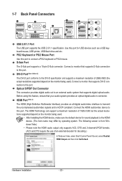
1-7 Back Panel Connectors USB 2.0/1.1 Port The USB port supports the USB 2.0/1.1 specification. PS/2 Keyboard or PS/2 Mouse Port Use this port. Connect a monitor that supports D-Sub connection to this port to an external audio system that your audio system provides an optical digital audio in connector. Before using this port. The HDMI Technology can support a maximum resolution of an external decoder for decoding.) In Windows Vista, select Start>Control Panel>Sound, select Realtek HDMI Output and then click Set Default. The following screen is from Windows Vista.) • Please ...
1-7 Back Panel Connectors USB 2.0/1.1 Port The USB port supports the USB 2.0/1.1 specification. PS/2 Keyboard or PS/2 Mouse Port Use this port. Connect a monitor that supports D-Sub connection to this port to an external audio system that your audio system provides an optical digital audio in connector. Before using this port. The HDMI Technology can support a maximum resolution of an external decoder for decoding.) In Windows Vista, select Start>Control Panel>Sound, select Realtek HDMI Output and then click Set Default. The following screen is from Windows Vista.) • Please ...
