Manual
Page 1
GA-880GMA-UD2H AM3 socket motherboard for AMD Phenom™ II processor/AMD Athlon™ II processor User's Manual Rev. 2002 12ME-880GA2H-2002R
GA-880GMA-UD2H AM3 socket motherboard for AMD Phenom™ II processor/AMD Athlon™ II processor User's Manual Rev. 2002 12ME-880GA2H-2002R
Manual
Page 2
Motherboard GA-880GMA-UD2H Apr. 12, 2010 Motherboard GA-880GMA-UD2H Apr. 12, 2010
Motherboard GA-880GMA-UD2H Apr. 12, 2010 Motherboard GA-880GMA-UD2H Apr. 12, 2010
Manual
Page 3
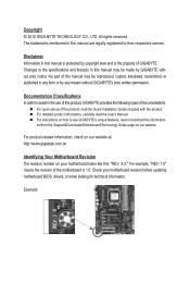
... for technical information. For product-related information, check on our website at: http://www.gigabyte.com.tw Identifying Your Motherboard Revision The revision number on our website. Check your motherboard looks like this manual may be made by GIGABYTE without GIGABYTE's prior written permission. Disclaimer Information in this manual may be reproduced, copied, translated, transmitted...
... for technical information. For product-related information, check on our website at: http://www.gigabyte.com.tw Identifying Your Motherboard Revision The revision number on our website. Check your motherboard looks like this manual may be made by GIGABYTE without GIGABYTE's prior written permission. Disclaimer Information in this manual may be reproduced, copied, translated, transmitted...
Manual
Page 4
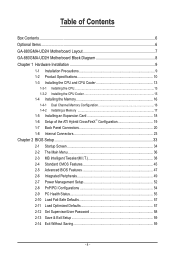
Table of Contents Box Contents...6 Optional Items...6 GA-880GMA-UD2H Motherboard Layout 7 GA-880GMA-UD2H Motherboard Block Diagram 8 Chapter 1 Hardware Installation 9 1-1 Installation Precautions 9 1-2 Product Specifications 10 1-3 Installing the CPU and CPU Cooler 13 1-3-1 Installing the CPU 13 1-3-2 Installing the CPU Cooler ...
Table of Contents Box Contents...6 Optional Items...6 GA-880GMA-UD2H Motherboard Layout 7 GA-880GMA-UD2H Motherboard Block Diagram 8 Chapter 1 Hardware Installation 9 1-1 Installation Precautions 9 1-2 Product Specifications 10 1-3 Installing the CPU and CPU Cooler 13 1-3-1 Installing the CPU 13 1-3-2 Installing the CPU Cooler ...
Manual
Page 6
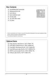
... SATA power cable (Part No. 12CF1-2SERPW-0*R) S/PDIF In and Out cable (Part No. 12CR1-1SPINO-1*R) COM port cable (Part No. 12CF1-1CM001-3*R) - 6 - Box Contents GA-880GMA-UD2H motherboard Motherboard driver disk User's Manual Quick Installation Guide One IDE cable Two SATA 3Gb/s cables I/O Shield • The box contents above are subject to change without...
... SATA power cable (Part No. 12CF1-2SERPW-0*R) S/PDIF In and Out cable (Part No. 12CR1-1SPINO-1*R) COM port cable (Part No. 12CF1-1CM001-3*R) - 6 - Box Contents GA-880GMA-UD2H motherboard Motherboard driver disk User's Manual Quick Installation Guide One IDE cable Two SATA 3Gb/s cables I/O Shield • The box contents above are subject to change without...
Manual
Page 7
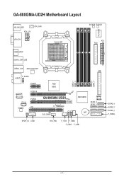
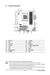
TSB43AB23 CLR_CMOS DDR3_1 DDR3_2 DDR3_3 DDR3_4 IDE AMD SB850 JMicron JMB368 SATA3_3 SATA3_1 BAT SPDIF_IO COM SYS_FAN F_1394 F_USB2 F_USB3 F_USB1 SATA3_4 SATA3_2 SATA3_0 F_PANEL - 7 - GA-880GMA-UD2H Motherboard Layout KB_MS_USB ATX_12V CPU_FAN VGA_DVI Socket AM3 M_BIOS B_BIOS ATX FDD iTE IT8720 HDMI_SPDIF ESATA_1394_USB USB30_LAN NEC D720200F1 F_AUDIO AUDIO PCIEX1 Realtek RTL8111D CD_IN CODEC PCIEX16 PCIEX4 PCI AMD 880G GA-880GMA-UD2H T.I.
TSB43AB23 CLR_CMOS DDR3_1 DDR3_2 DDR3_3 DDR3_4 IDE AMD SB850 JMicron JMB368 SATA3_3 SATA3_1 BAT SPDIF_IO COM SYS_FAN F_1394 F_USB2 F_USB3 F_USB1 SATA3_4 SATA3_2 SATA3_0 F_PANEL - 7 - GA-880GMA-UD2H Motherboard Layout KB_MS_USB ATX_12V CPU_FAN VGA_DVI Socket AM3 M_BIOS B_BIOS ATX FDD iTE IT8720 HDMI_SPDIF ESATA_1394_USB USB30_LAN NEC D720200F1 F_AUDIO AUDIO PCIEX1 Realtek RTL8111D CD_IN CODEC PCIEX16 PCIEX4 PCI AMD 880G GA-880GMA-UD2H T.I.
Manual
Page 8
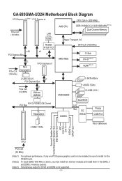
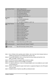
... must install two memory modules and install them in the DDR3_3 and DDR3_4 memory sockets. (Note 3) Simultaneous output for DVI-D and HDMI is not supported. - 8 - GA-880GMA-UD2H Motherboard Block Diagram 1 PCI Express x16 (Note 1) 1 PCI Express x4 CPU CLK+/- (200 MHz) PCIe CLK (100 MHz) LAN RJ45 AM3 CPU DDR3 1800(O.C.)/1333/1066...
... must install two memory modules and install them in the DDR3_3 and DDR3_4 memory sockets. (Note 3) Simultaneous output for DVI-D and HDMI is not supported. - 8 - GA-880GMA-UD2H Motherboard Block Diagram 1 PCI Express x16 (Note 1) 1 PCI Express x4 CPU CLK+/- (200 MHz) PCIe CLK (100 MHz) LAN RJ45 AM3 CPU DDR3 1800(O.C.)/1333/1066...
Manual
Page 9
...have an ESD wrist strap, keep your hands dry and first touch a metal object to eliminate static electricity. • Prior to installing the motherboard, please have a problem related to the use of an antistatic pad or within the computer casing. • Do not place the computer system...within an electrostatic shielding container. • Before unplugging the power supply cable from the power outlet before installing or removing the motherboard or other hardware components. • When connecting hardware components to the internal connectors on the power, make sure they are uncertain...
...have an ESD wrist strap, keep your hands dry and first touch a metal object to eliminate static electricity. • Prior to installing the motherboard, please have a problem related to the use of an antistatic pad or within the computer casing. • Do not place the computer system...within an electrostatic shielding container. • Before unplugging the power supply cable from the power outlet before installing or removing the motherboard or other hardware components. • When connecting hardware components to the internal connectors on the power, make sure they are uncertain...
Manual
Page 12
... CPU/system fan speed control function is supported will depend on the CPU/system cooler you install. (Note 7) Available functions in EasyTune may differ by motherboard model.
... CPU/system fan speed control function is supported will depend on the CPU/system cooler you install. (Note 7) Available functions in EasyTune may differ by motherboard model.
Manual
Page 13
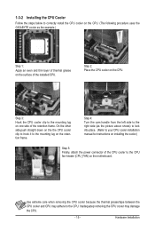
....) • Apply an even and thin layer of thermal grease on the computer if the CPU cooler is not recommended that the motherboard supports the CPU. (Go to GIGABYTE's website for the peripherals. The CPU cannot be set the frequency beyond hardware specifications since it does not meet the standard requirements for...
....) • Apply an even and thin layer of thermal grease on the computer if the CPU cooler is not recommended that the motherboard supports the CPU. (Go to GIGABYTE's website for the peripherals. The CPU cannot be set the frequency beyond hardware specifications since it does not meet the standard requirements for...
Manual
Page 14
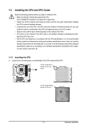
... position. CPU Socket Locking Lever Step 1: Completely lift up the CPU socket locking lever. Follow the steps below to correctly install the CPU into the motherboard CPU socket. • Before installing the CPU, make sure to turn off the computer and unplug the power cord from the power outlet to prevent...
... position. CPU Socket Locking Lever Step 1: Completely lift up the CPU socket locking lever. Follow the steps below to correctly install the CPU into the motherboard CPU socket. • Before installing the CPU, make sure to turn off the computer and unplug the power cord from the power outlet to prevent...
Manual
Page 15
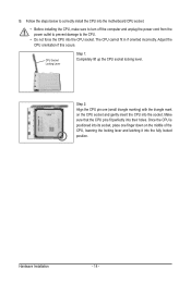
... below to correctly install the CPU cooler on the CPU. (The following procedure uses the GIGABYTE cooler as the picture above shows) to lock into place. (Refer to your CPU cooler installation manual for instructions on the motherboard. Step 2: Place the CPU cooler on the surface of the CPU cooler to the...
... below to correctly install the CPU cooler on the CPU. (The following procedure uses the GIGABYTE cooler as the picture above shows) to lock into place. (Refer to your CPU cooler installation manual for instructions on the motherboard. Step 2: Place the CPU cooler on the surface of the CPU cooler to the...

Manual
Page 16
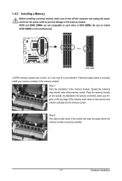
.... Enabling Dual Channel memory mode will automatically detect the specifications and capacity of the memory. The four DDR3 memory sockets are unable to GIGABYTE's website for optimum performance. DS/SS DS/SS Four Modules DS/SS DS/SS DS/SS DS/SS (SS=Single-Sided, DS... same capacity, brand, speed, and chips be used . (Go to insert the memory, switch the direction. 1-4-1 Dual Channel Memory Configuration This motherboard provides four DDR3 memory sockets and supports Dual Channel Technology. It is installed. 2. Hardware Installation - 16 - Dual Channel mode cannot be installed ...
.... Enabling Dual Channel memory mode will automatically detect the specifications and capacity of the memory. The four DDR3 memory sockets are unable to GIGABYTE's website for optimum performance. DS/SS DS/SS Four Modules DS/SS DS/SS DS/SS DS/SS (SS=Single-Sided, DS... same capacity, brand, speed, and chips be used . (Go to insert the memory, switch the direction. 1-4-1 Dual Channel Memory Configuration This motherboard provides four DDR3 memory sockets and supports Dual Channel Technology. It is installed. 2. Hardware Installation - 16 - Dual Channel mode cannot be installed ...
Manual
Page 17
... the memory module. Spread the retaining clips at both ends of the socket will snap into the memory socket. Place the memory module on this motherboard. Step 2: The clips at both ends of the memory socket.
... the memory module. Spread the retaining clips at both ends of the socket will snap into the memory socket. Place the memory module on this motherboard. Step 2: The clips at both ends of the memory socket.
Manual
Page 18
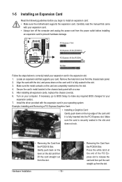
... the slot and then lift the card straight out from the power outlet before you begin to install an expansion card: • Make sure the motherboard supports the expansion card. Example: Installing and Removing a PCI Express Graphics Card: • Installing a Graphics Card: Gently push down on the card are completely inserted...
... the slot and then lift the card straight out from the power outlet before you begin to install an expansion card: • Make sure the motherboard supports the expansion card. Example: Installing and Removing a PCI Express Graphics Card: • Installing a Graphics Card: Gently push down on the card are completely inserted...
Manual
Page 19
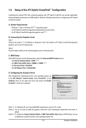
...not have to Disabled. - Set Internal Graphics Mode to the ATI Catalyst™ Control Center. Configuring the Graphics Driver After installing the motherboard driver in BIOS Setup, be sure to 256MB or 512MB. (Note 3) - Select CrossFire™ on the Graphics menu on the PCI...graphics card, ATI Hybrid CrossFireX can provide significantly advanced display performance for AMD platform. A. System Requirements - An ATI Hybrid CrossFireX-supported motherboard and correct driver - C. Set UMA Frame Buffer Size to disable the CrossFire function in - Set Surround View to install the ...
...not have to Disabled. - Set Internal Graphics Mode to the ATI Catalyst™ Control Center. Configuring the Graphics Driver After installing the motherboard driver in BIOS Setup, be sure to 256MB or 512MB. (Note 3) - Select CrossFire™ on the Graphics menu on the PCI...graphics card, ATI Hybrid CrossFireX can provide significantly advanced display performance for AMD platform. A. System Requirements - An ATI Hybrid CrossFireX-supported motherboard and correct driver - C. Set UMA Frame Buffer Size to disable the CrossFire function in - Set Surround View to install the ...

Manual
Page 21
...not supported. • When removing the cable connected to a back panel connector, first remove the cable from your device and then remove it from the motherboard. • When removing the cable, pull it side to side to Chapter 2, "BIOS Setup," "Advanced BIOS Features," for more information) • ...Internet connection at up to connect an external SATA device. Do not rock it straight out from the connector. Dual Display Configurations: This motherboard provides three ports for an IEEE 1394a device. Playback of HD DVD and Blu-ray Discs: In order to get better playback quality,...
...not supported. • When removing the cable connected to a back panel connector, first remove the cable from your device and then remove it from the motherboard. • When removing the cable, pull it side to side to Chapter 2, "BIOS Setup," "Advanced BIOS Features," for more information) • ...Internet connection at up to connect an external SATA device. Do not rock it straight out from the connector. Dual Display Configurations: This motherboard provides three ports for an IEEE 1394a device. Playback of HD DVD and Blu-ray Discs: In order to get better playback quality,...
Manual
Page 23
..., make sure your devices are compliant with the connectors you wish to connect. • Before installing the devices, be sure to the connector on the motherboard. - 23 - Unplug the power cord from the power outlet to prevent damage to the devices. • After installing the device and before connecting external devices...
..., make sure your devices are compliant with the connectors you wish to connect. • Before installing the devices, be sure to the connector on the motherboard. - 23 - Unplug the power cord from the power outlet to prevent damage to the devices. • After installing the device and before connecting external devices...
Manual
Page 24
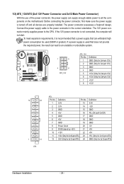
... for 2x12-pin ATX) GND (Only for 2x12-pin ATX) Hardware Installation - 24 - If a power supply is turned off and all the components on the motherboard. Before connecting the power connector, first make sure the power supply is used (500W or greater). If the 12V power connector is recommended that a power...
... for 2x12-pin ATX) GND (Only for 2x12-pin ATX) Hardware Installation - 24 - If a power supply is turned off and all the components on the motherboard. Before connecting the power connector, first make sure the power supply is used (500W or greater). If the 12V power connector is recommended that a power...
Manual
Page 25
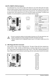
The motherboard supports CPU fan speed control, which requires the use of different color. Definition 1 1 GND CPU_FAN 2 +12V / Speed Control 3 Sense 4 Speed Control 1 SYS_FAN SYS_FAN: Pin No. 1 2 3 4 ..., please contact the local dealer. 34 33 2 1 - 25 - The pin 1 of floppy disk drives supported are not configuration jumper blocks. 3/4) CPU_FAN/SYS_FAN (Fan Headers) The motherboard has a 4-pin CPU fan header (CPU_FAN) and a 4-pin (SYS_FAN) system fan header. When connecting a fan cable, be installed inside the chassis. For optimum heat dissipation...
The motherboard supports CPU fan speed control, which requires the use of different color. Definition 1 1 GND CPU_FAN 2 +12V / Speed Control 3 Sense 4 Speed Control 1 SYS_FAN SYS_FAN: Pin No. 1 2 3 4 ..., please contact the local dealer. 34 33 2 1 - 25 - The pin 1 of floppy disk drives supported are not configuration jumper blocks. 3/4) CPU_FAN/SYS_FAN (Fan Headers) The motherboard has a 4-pin CPU fan header (CPU_FAN) and a 4-pin (SYS_FAN) system fan header. When connecting a fan cable, be installed inside the chassis. For optimum heat dissipation...


