
Manual
Page 1
GA-7PESH1 GA-7PESH2 Dual LGA2011 sockets motherboard for Intel® E5-2600 series processors User's Manual Rev. 1001
GA-7PESH1 GA-7PESH2 Dual LGA2011 sockets motherboard for Intel® E5-2600 series processors User's Manual Rev. 1001

Manual
Page 3
Table of Contents Box Contents...4 GA-7PESH1/7PESH2 Motherboard Layout 5 Chapter 1 Hardware Installation 8 1-1 Installation Precautions 8 1-2 Product Specifications 9 1-3 Installing the CPU and CPU Cooler 11 1-3-1 Installing the CPU...11 1-3-2 Installing the CPU Cooler 13 1-4 Installing the Memory 14 1-4-1 Four Channel Memory Configuration 14 1-4-2 Installing a Memory 15 1-4-3 DIMM Population Table 15 1-5 Back Panel Connectors 16 1-6 Internal Connectors 18 1-7 Jumper Setting 29 - 3 -
Table of Contents Box Contents...4 GA-7PESH1/7PESH2 Motherboard Layout 5 Chapter 1 Hardware Installation 8 1-1 Installation Precautions 8 1-2 Product Specifications 9 1-3 Installing the CPU and CPU Cooler 11 1-3-1 Installing the CPU...11 1-3-2 Installing the CPU Cooler 13 1-4 Installing the Memory 14 1-4-1 Four Channel Memory Configuration 14 1-4-2 Installing a Memory 15 1-4-3 DIMM Population Table 15 1-5 Back Panel Connectors 16 1-6 Internal Connectors 18 1-7 Jumper Setting 29 - 3 -
Manual
Page 4
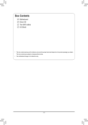
The box contents are for reference only. - 4 - Box Contents Motherboard Driver CD Two SATA cables I/O Shield • The box contents above are subject to change without notice. • The motherboard image is for reference only and the actual items shall depend on the product package you obtain.
The box contents are for reference only. - 4 - Box Contents Motherboard Driver CD Two SATA cables I/O Shield • The box contents above are subject to change without notice. • The motherboard image is for reference only and the actual items shall depend on the product package you obtain.

Manual
Page 5
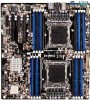
GA-7PESH1/7PESH2 Motherboard Layout 41 42 44 45 47 49 51 1 2 3 4 5 6 43 46 48 50 40 39 38 37 36 35 34 60 52 59 53 54 33 58 32 55 31 30 57 56 29 28 25 24 89 7 10 11 12 13 14 19 18 15 27 26 23 22 21 20 17 16 - 5 -
GA-7PESH1/7PESH2 Motherboard Layout 41 42 44 45 47 49 51 1 2 3 4 5 6 43 46 48 50 40 39 38 37 36 35 34 60 52 59 53 54 33 58 32 55 31 30 57 56 29 28 25 24 89 7 10 11 12 13 14 19 18 15 27 26 23 22 21 20 17 16 - 5 -
Manual
Page 7
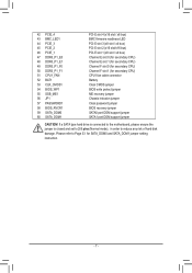
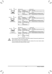
Please refer to reduce any risk of hard disk damage. If a SATA type hard drive is connected to the motherboard, please ensure the jumper is closed and set to 2-3 pins (Normal mode), in order to Page 33 for secondary CPU) CPU1 fan cable connector Battery ...
Please refer to reduce any risk of hard disk damage. If a SATA type hard drive is connected to the motherboard, please ensure the jumper is closed and set to 2-3 pins (Normal mode), in order to Page 33 for secondary CPU) CPU1 fan cable connector Battery ...
Manual
Page 8
...If you do not have an ESD wrist strap, keep your hardware components are connected tightly and securely. • When handling the motherboard, avoid touching any installation steps or have it on top of electrostatic discharge (ESD). Prior to installation, carefully read the user's ...-temperature environment. • Turning on the power, make sure they are connected. • To prevent damage to the motherboard, do not remove or break motherboard S/N (Serial Number) sticker or warranty sticker provided by unplugging the power cord from the power outlet before installing or removing...
...If you do not have an ESD wrist strap, keep your hardware components are connected tightly and securely. • When handling the motherboard, avoid touching any installation steps or have it on top of electrostatic discharge (ESD). Prior to installation, carefully read the user's ...-temperature environment. • Turning on the power, make sure they are connected. • To prevent damage to the motherboard, do not remove or break motherboard S/N (Serial Number) sticker or warranty sticker provided by unplugging the power cord from the power outlet before installing or removing...

Manual
Page 11
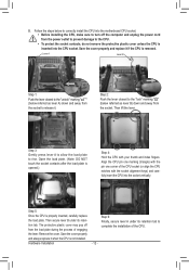
....) • Apply an even and thin layer of thermal grease on the computer if the CPU cooler is not recommended that the motherboard supports the CPU. (Go to GIGABYTE's website for the peripherals. Hardware Installation age of the CPU. • Do not turn off the computer and unplug the power... Marking on the CPU. Pin One Corner of the CPU. It is not installed, otherwise overheating and dam- Locate the alignment keys on the motherboard CPU socket and the notches on the CPU Notch Notch - 11 - 1-3 Installing the CPU and CPU Cooler Read the following guidelines before installing ...
....) • Apply an even and thin layer of thermal grease on the computer if the CPU cooler is not recommended that the motherboard supports the CPU. (Go to GIGABYTE's website for the peripherals. Hardware Installation age of the CPU. • Do not turn off the computer and unplug the power... Marking on the CPU. Pin One Corner of the CPU. It is not installed, otherwise overheating and dam- Locate the alignment keys on the motherboard CPU socket and the notches on the CPU Notch Notch - 11 - 1-3 Installing the CPU and CPU Cooler Read the following guidelines before installing ...
Manual
Page 12
... closest to the CPU. •• To protect the socket contacts, do not remove the protective plastic cover unless the CPU is inserted into the motherboard CPU socket. •• Before installing the CPU, make sure to turn off from the socket to complete the installation of the CPU. - 12 - Step...
... closest to the CPU. •• To protect the socket contacts, do not remove the protective plastic cover unless the CPU is inserted into the motherboard CPU socket. •• Before installing the CPU, make sure to turn off from the socket to complete the installation of the CPU. - 12 - Step...
Manual
Page 13
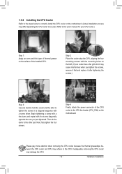
....) Step 1: Apply an even and thin layer of thermal grease on the surface of the CPU cooler to the CPU fan header (CPU_FAN) on the motherboard. (Actual installation process may cause interference when you tighten the screws, remove it first and replace it after tightening the screws.) Step 3: Use one you..., attach the power connector of the installed CPU. 1-3-2 Installing the CPU Cooler Refer to the steps below to correctly install the CPU cooler on the motherboard. Inadequately removing the CPU cooler may adhere to the CPU.
....) Step 1: Apply an even and thin layer of thermal grease on the surface of the CPU cooler to the CPU fan header (CPU_FAN) on the motherboard. (Actual installation process may cause interference when you tighten the screws, remove it first and replace it after tightening the screws.) Step 3: Use one you..., attach the power connector of the installed CPU. 1-3-2 Installing the CPU Cooler Refer to the steps below to correctly install the CPU cooler on the motherboard. Inadequately removing the CPU cooler may adhere to the CPU.
Manual
Page 14
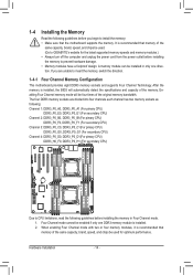
... DDR3_P0_B1 DDR3_P0_B0 DDR3_P0_A1 DDR3_P0_A0 DDR3_P0_C0 DDR3_P0_C1 DDR3_P0_D0 DDR3_P0_D1 Due to CPU limitations, read the following guidelines before you begin to GIGABYTE's website for optimum performance. Hardware Installation - 14 - It is recommended that memory of the same capacity, brand...power outlet before installing the memory to insert the memory, switch the direction. 1-4-1 Four Channel Memory Configuration This motherboard provides eight DDR3 memory sockets and supports Four Channel Technology. 1-4 Installing the Memory Read the following guidelines before ...
... DDR3_P0_B1 DDR3_P0_B0 DDR3_P0_A1 DDR3_P0_A0 DDR3_P0_C0 DDR3_P0_C1 DDR3_P0_D0 DDR3_P0_D1 Due to CPU limitations, read the following guidelines before you begin to GIGABYTE's website for optimum performance. Hardware Installation - 14 - It is recommended that memory of the same capacity, brand...power outlet before installing the memory to insert the memory, switch the direction. 1-4-1 Four Channel Memory Configuration This motherboard provides eight DDR3 memory sockets and supports Four Channel Technology. 1-4 Installing the Memory Read the following guidelines before ...
Manual
Page 15
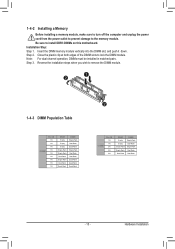
...-Rank Dual-Rank Dual-Rank Dual-Rank - 15 - Close the plastic clip at both edges of the DIMM slots to install DDR3 DIMMs on this motherboard. Hardware Installation Be sure to lock the DIMM module. Installation Step: Step 1. Note: For dual-channel operation, DIMMs must be installed in matched pairs...
...-Rank Dual-Rank Dual-Rank Dual-Rank - 15 - Close the plastic clip at both edges of the DIMM slots to install DDR3 DIMMs on this motherboard. Hardware Installation Be sure to lock the DIMM module. Installation Step: Step 1. Note: For dual-channel operation, DIMMs must be installed in matched pairs...
Manual
Page 17
... Installation Do not rock it side to side to a back panel connector, first remove the cable from your device and then remove it from the motherboard. • When removing the cable, pull it straight out from the connector. Speed LED Link Activity LED 10/100 LAN Port MLAN Speed LED: Link...
... Installation Do not rock it side to side to a back panel connector, first remove the cable from your device and then remove it from the motherboard. • When removing the cable, pull it straight out from the connector. Speed LED Link Activity LED 10/100 LAN Port MLAN Speed LED: Link...

Manual
Page 19
Unplug the power cord from the power outlet to prevent damage to the devices. • After installing the device and before connecting external devices: • First make sure the device cable has been securely attached to turn off the devices and your computer. Read the following guidelines before turning on the computer, make sure your devices are compliant with the connectors you wish to connect. • Before installing the devices, be sure to the connector on the motherboard. - 19 - Hardware Installation
Unplug the power cord from the power outlet to prevent damage to the devices. • After installing the device and before connecting external devices: • First make sure the device cable has been securely attached to turn off the devices and your computer. Read the following guidelines before turning on the computer, make sure your devices are compliant with the connectors you wish to connect. • Before installing the devices, be sure to the connector on the motherboard. - 19 - Hardware Installation
Manual
Page 20
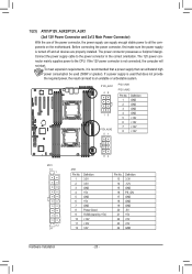
... ATX1 13 1 ATX1 Pin No. The power connector possesses a foolproof design. If the 12V power connector is turned off and all the components on the motherboard.
... ATX1 13 1 ATX1 Pin No. The power connector possesses a foolproof design. If the 12V power connector is turned off and all the components on the motherboard.
Manual
Page 21
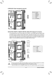
The motherboard supports CPU fan speed control, which requires the use of a CPU fan with fan speed control design. Overheating may result in the correct orientation (the ... (Power management connector) 1 5 Pin No. 1 2 3 4 5 Definition SMB CLK SMB DATA SMB Alert GND 3.3V Sense 5/6/7/8) CPU0_FAN/CPU1_FAN/SYS_FAN1/SYS_FAN2 (CPU Fan/System Fan Headers) The motherboard has a 4-pin CPU fan header (CPU_FAN1/2), a 4-pin (FAN4) system fan headers. Most fan headers possess a foolproof insertion design.
The motherboard supports CPU fan speed control, which requires the use of a CPU fan with fan speed control design. Overheating may result in the correct orientation (the ... (Power management connector) 1 5 Pin No. 1 2 3 4 5 Definition SMB CLK SMB DATA SMB Alert GND 3.3V Sense 5/6/7/8) CPU0_FAN/CPU1_FAN/SYS_FAN1/SYS_FAN2 (CPU Fan/System Fan Headers) The motherboard has a 4-pin CPU fan header (CPU_FAN1/2), a 4-pin (FAN4) system fan headers. Most fan headers possess a foolproof insertion design.

Manual
Page 30
...). 2) BIOS_WP1 (BIOS Write Protect Jumper) 1 1-2 Close: Normal operation. (Default setting) 1 2-3 Close: Enable BIOS write protect function. Failure to do so may cause damage to the motherboard. • After system restart, go to BIOS Setup Exit menu and load factory defaults (select Load Default Values) or manually configure the BIOS settings (refer...
...). 2) BIOS_WP1 (BIOS Write Protect Jumper) 1 1-2 Close: Normal operation. (Default setting) 1 2-3 Close: Enable BIOS write protect function. Failure to do so may cause damage to the motherboard. • After system restart, go to BIOS Setup Exit menu and load factory defaults (select Load Default Values) or manually configure the BIOS settings (refer...
Manual
Page 33
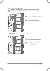
If a SATA type hard drive is connected to the motherboard, please ensure the jumper is closed and set to 2-3 pins (Normal mode), in order to reduce any risk of hard disk damage. 1 1-2 Close: Enable SATA0/SATA1 port DOM support. 1 2-3 Close: Normal mode. (Default setting) 9) FLASH_DP1 (Flash Descriptor Security Jumper) 1 1-2 Close: Flash Descriptor Security Overridden 1 2-3 Close: Flash Descriptor Security in effect. (Default setting) - 33 - Hardware Installation 7/8) SATA_DOM0/1 (SATA DOM Jumper) CAUTION!
If a SATA type hard drive is connected to the motherboard, please ensure the jumper is closed and set to 2-3 pins (Normal mode), in order to reduce any risk of hard disk damage. 1 1-2 Close: Enable SATA0/SATA1 port DOM support. 1 2-3 Close: Normal mode. (Default setting) 9) FLASH_DP1 (Flash Descriptor Security Jumper) 1 1-2 Close: Flash Descriptor Security Overridden 1 2-3 Close: Flash Descriptor Security in effect. (Default setting) - 33 - Hardware Installation 7/8) SATA_DOM0/1 (SATA DOM Jumper) CAUTION!
Manual
Page 34
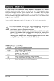
...with caution. Chapter 2 BIOS Setup BIOS (Basic Input and Output System) records hardware parameters of the system in the EFI on the motherboard supplies the necessary power to the CMOS to keep the configuration values in the CMOS. To access the BIOS Setup program, press the ...default values. (Refer to the "Load Optimized Defaults" section in system malfunction. • It is turned off, the battery on the motherboard. Inadequately altering the settings may result in this chapter or introductions of general help Restore the previous BIOS settings for the current submenus Load ...
...with caution. Chapter 2 BIOS Setup BIOS (Basic Input and Output System) records hardware parameters of the system in the EFI on the motherboard supplies the necessary power to the CMOS to keep the configuration values in the CMOS. To access the BIOS Setup program, press the ...default values. (Refer to the "Load Optimized Defaults" section in system malfunction. • It is turned off, the battery on the motherboard. Inadequately altering the settings may result in this chapter or introductions of general help Restore the previous BIOS settings for the current submenus Load ...
Manual
Page 52
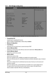
Current Memory Mode Displays the cuurent memory mode. When set to Mirroring mode, the motherboard maintains two identical (redundant) copies of coorectable errors is put online and used to trigger fail-over. When set to Indendent mode, all DIMMs... Displays the cuurent memory speed. BIOS Setup - 52 - 2-3-1 North Bridge Configuration Compatibility RID Enable/Disable Compatibility RID function. When set to Lockstep mode, the motherboard uses two areas of memory to run the same set to the operation system. When set of the failed memory. Memory Configuration Total Memory Determines...
Current Memory Mode Displays the cuurent memory mode. When set to Mirroring mode, the motherboard maintains two identical (redundant) copies of coorectable errors is put online and used to trigger fail-over. When set to Indendent mode, all DIMMs... Displays the cuurent memory speed. BIOS Setup - 52 - 2-3-1 North Bridge Configuration Compatibility RID Enable/Disable Compatibility RID function. When set to Lockstep mode, the motherboard uses two areas of memory to run the same set to the operation system. When set of the failed memory. Memory Configuration Total Memory Determines...


