Manual
Page 1
GA-785GMT-USB3 AM3 socket motherboard for AMD Phenom™ II processor/ AMD Athlon™ II processor User's Manual Rev. 1001 12ME-785TB3-1001R
GA-785GMT-USB3 AM3 socket motherboard for AMD Phenom™ II processor/ AMD Athlon™ II processor User's Manual Rev. 1001 12ME-785TB3-1001R
Manual
Page 2
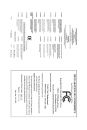
Motherboard GA-785GMT-USB3 Jan 16, 2010 Motherboard GA-785GMT-USB3 Jan. 16, 2010
Motherboard GA-785GMT-USB3 Jan 16, 2010 Motherboard GA-785GMT-USB3 Jan. 16, 2010
Manual
Page 3
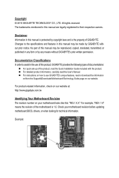
... how to assist in this manual may be made by GIGABYTE without GIGABYTE's prior written permission. For example, "REV: 1.0" means the revision of the motherboard is the property of GIGABYTE. No part of this product, GIGABYTE provides the following types of documentations: For quick set-up...TECHNOLOGY CO., LTD. For product-related information, check on our website at: http://www.gigabyte.com.tw Identifying Your Motherboard Revision The revision number on our website. Check your motherboard looks like this manual is protected by any form or by copyright laws and is ...
... how to assist in this manual may be made by GIGABYTE without GIGABYTE's prior written permission. For example, "REV: 1.0" means the revision of the motherboard is the property of GIGABYTE. No part of this product, GIGABYTE provides the following types of documentations: For quick set-up...TECHNOLOGY CO., LTD. For product-related information, check on our website at: http://www.gigabyte.com.tw Identifying Your Motherboard Revision The revision number on our website. Check your motherboard looks like this manual is protected by any form or by copyright laws and is ...
Manual
Page 4
Table of Contents Box Contents...6 Optional Items...6 GA-785GMT-USB3 Motherboard Layout 7 GA-785GMT-USB3 Motherboard Block Diagram 8 Chapter 1 Hardware Installation 9 1-1 Installation Precautions 9 1-2 Product Specifications 10 1-3 Installing the CPU and CPU Cooler 13 1-3-1 Installing the CPU 13 1-3-2 Installing the CPU Cooler ...
Table of Contents Box Contents...6 Optional Items...6 GA-785GMT-USB3 Motherboard Layout 7 GA-785GMT-USB3 Motherboard Block Diagram 8 Chapter 1 Hardware Installation 9 1-1 Installation Precautions 9 1-2 Product Specifications 10 1-3 Installing the CPU and CPU Cooler 13 1-3-1 Installing the CPU 13 1-3-2 Installing the CPU Cooler ...
Manual
Page 6
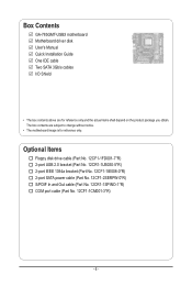
... SATA power cable (Part No. 12CF1-2SERPW-0*R) S/PDIF In and Out cable (Part No. 12CR1-1SPINO-1*R) COM port cable (Part No. 12CF1-1CM001-3*R) - 6 - Box Contents GA-785GMT-USB3 motherboard Motherboard driver disk User's Manual Quick Installation Guide One IDE cable Two SATA 3Gb/s cables I/O Shield • The box contents above are subject to change without...
... SATA power cable (Part No. 12CF1-2SERPW-0*R) S/PDIF In and Out cable (Part No. 12CR1-1SPINO-1*R) COM port cable (Part No. 12CF1-1CM001-3*R) - 6 - Box Contents GA-785GMT-USB3 motherboard Motherboard driver disk User's Manual Quick Installation Guide One IDE cable Two SATA 3Gb/s cables I/O Shield • The box contents above are subject to change without...
Manual
Page 7
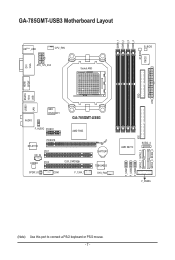
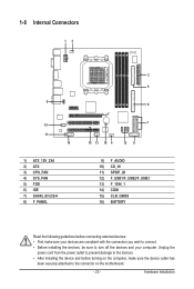
FDD ATX GA-785GMT-USB3 Motherboard Layout DDR3_1 DDR3_2 DDR3_3 DDR3_4 M_BIOS IT8720 DVI VGA KB(Note)_USB CPU_FAN ATX_12V_2X4 Socket AM3 B_BIOS SPDIF HDMI USB 1394 USB30 ESATA LAN AUDIO NEC D720200F1 F_AUDIO PCIEX1 GA-785GMT-USB3 AMD 785G PCIEX16 RTL8111D PCI1 CD_IN CODEC PCI2 CLR_CMOS SPDIF_IO COM F_1394_1 BATTERY TSB43AB23 SYS_FAN AMD SB710 SATA2_4 SATA2_1 SATA2_3 F_USB3 F_USB2 F_USB1 F_PANEL IDE SATA2_0 SATA2_2 (Note) Use this port to connect a PS/2 keyboard or PS/2 mouse. - 7 -
FDD ATX GA-785GMT-USB3 Motherboard Layout DDR3_1 DDR3_2 DDR3_3 DDR3_4 M_BIOS IT8720 DVI VGA KB(Note)_USB CPU_FAN ATX_12V_2X4 Socket AM3 B_BIOS SPDIF HDMI USB 1394 USB30 ESATA LAN AUDIO NEC D720200F1 F_AUDIO PCIEX1 GA-785GMT-USB3 AMD 785G PCIEX16 RTL8111D PCI1 CD_IN CODEC PCI2 CLR_CMOS SPDIF_IO COM F_1394_1 BATTERY TSB43AB23 SYS_FAN AMD SB710 SATA2_4 SATA2_1 SATA2_3 F_USB3 F_USB2 F_USB1 F_PANEL IDE SATA2_0 SATA2_2 (Note) Use this port to connect a PS/2 keyboard or PS/2 mouse. - 7 -
Manual
Page 8
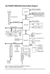
GA-785GMT-USB3 Motherboard Block Diagram PCIe CLK (100 MHz) 1 PCI Express x16 CPU CLK+/- (200 MHz) AM3 CPU DDR3 1800 (O.C.)/1333/1066 MHz Dual Channel Memory Hyper Transport 3.0 ...
GA-785GMT-USB3 Motherboard Block Diagram PCIe CLK (100 MHz) 1 PCI Express x16 CPU CLK+/- (200 MHz) AM3 CPU DDR3 1800 (O.C.)/1333/1066 MHz Dual Channel Memory Hyper Transport 3.0 ...
Manual
Page 9
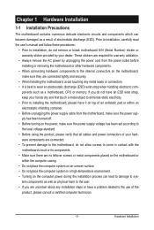
...• Do not place the computer system on an uneven surface. • Do not place the computer system in contact with the motherboard circuit or its components. • Make sure there are uncertain about any installation steps or have it on top of the product, ...please consult a certified computer technician. - 9 - Chapter 1 Hardware Installation 1-1 Installation Precautions The motherboard contains numerous delicate electronic circuits and components which can lead to damage to system components as well as physical harm to the user. • ...
...• Do not place the computer system on an uneven surface. • Do not place the computer system in contact with the motherboard circuit or its components. • Make sure there are uncertain about any installation steps or have it on top of the product, ...please consult a certified computer technician. - 9 - Chapter 1 Hardware Installation 1-1 Installation Precautions The motherboard contains numerous delicate electronic circuits and components which can lead to damage to system components as well as physical harm to the user. • ...

Manual
Page 12
... CPU/system fan speed control function is supported will depend on the CPU/system cooler you install. (Note 6) Available functions in EasyTune may differ by motherboard model.
... CPU/system fan speed control function is supported will depend on the CPU/system cooler you install. (Note 6) Available functions in EasyTune may differ by motherboard model.
Manual
Page 13
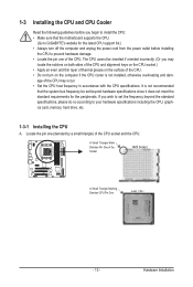
... socket.) • Apply an even and thin layer of thermal grease on the computer if the CPU cooler is not recommended that the motherboard supports the CPU. (Go to GIGABYTE's website for the peripherals. 1-3 Installing the CPU and CPU Cooler Read the following guidelines before you begin to install the CPU: •...
... socket.) • Apply an even and thin layer of thermal grease on the computer if the CPU cooler is not recommended that the motherboard supports the CPU. (Go to GIGABYTE's website for the peripherals. 1-3 Installing the CPU and CPU Cooler Read the following guidelines before you begin to install the CPU: •...
Manual
Page 14
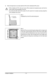
... on the CPU socket and gently insert the CPU into the fully locked position. Follow the steps below to correctly install the CPU into the motherboard CPU socket. • Before installing the CPU, make sure to turn off the computer and unplug the power cord from the power outlet to prevent...
... on the CPU socket and gently insert the CPU into the fully locked position. Follow the steps below to correctly install the CPU into the motherboard CPU socket. • Before installing the CPU, make sure to turn off the computer and unplug the power cord from the power outlet to prevent...
Manual
Page 15
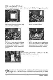
...even and thin layer of thermal grease on the retention frame. Step 3: Hook the CPU cooler clip to the mounting lug on the motherboard. Hardware Installation 1-3-2 Installing the CPU Cooler Follow the steps below to correctly install the CPU cooler on the CPU. (The following procedure uses ...the GIGABYTE cooler as the picture above shows) to lock into place. (Refer to your CPU cooler installation manual for instructions on installing the cooler.)...
...even and thin layer of thermal grease on the retention frame. Step 3: Hook the CPU cooler clip to the mounting lug on the motherboard. Hardware Installation 1-3-2 Installing the CPU Cooler Follow the steps below to correctly install the CPU cooler on the CPU. (The following procedure uses ...the GIGABYTE cooler as the picture above shows) to lock into place. (Refer to your CPU cooler installation manual for instructions on installing the cooler.)...
Manual
Page 16
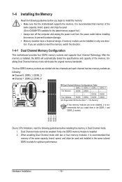
...list.) • Always turn off the computer and unplug the power cord from the power outlet before installing the memory to GIGABYTE's website for optimum performance. Hardware Installation - 16 - Enabling Dual Channel memory mode will automatically detect the specifications and capacity of..., read the following guidelines before you begin to insert the memory, switch the direction. 1-4-1 Dual Channel Memory Configuration This motherboard provides four DDR3 memory sockets and supports Dual Channel Technology. Dual Channel mode cannot be installed in the DDR3_1 and DDR3_2 sockets...
...list.) • Always turn off the computer and unplug the power cord from the power outlet before installing the memory to GIGABYTE's website for optimum performance. Hardware Installation - 16 - Enabling Dual Channel memory mode will automatically detect the specifications and capacity of..., read the following guidelines before you begin to insert the memory, switch the direction. 1-4-1 Dual Channel Memory Configuration This motherboard provides four DDR3 memory sockets and supports Dual Channel Technology. Dual Channel mode cannot be installed in the DDR3_1 and DDR3_2 sockets...

Manual
Page 17
... orientation of the memory, push down on the memory and insert it can only fit in the memory sockets. Place the memory module on this motherboard. Follow the steps below to the memory module. 1-4-2 Installing a Memory Before installing a memory module, make sure to turn off the computer and unplug the power...
... orientation of the memory, push down on the memory and insert it can only fit in the memory sockets. Place the memory module on this motherboard. Follow the steps below to the memory module. 1-4-2 Installing a Memory Before installing a memory module, make sure to turn off the computer and unplug the power...
Manual
Page 18
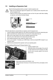
... on the card are completely inserted into the PCI Express slot. Secure the card's metal bracket to install an expansion card: • Make sure the motherboard supports the expansion card. Example: Installing and Removing a PCI Express Graphics Card: • Installing a Graphics Card: Gently push down on the slot and then lift...
... on the card are completely inserted into the PCI Express slot. Secure the card's metal bracket to install an expansion card: • Make sure the motherboard supports the expansion card. Example: Installing and Removing a PCI Express Graphics Card: • Installing a Graphics Card: Gently push down on the slot and then lift...
Manual
Page 19
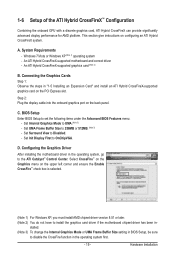
... Center. D. This section give instructions on the back panel. An ATI Hybrid CrossFireX-supported motherboard and correct driver - C. Hardware Installation A. Configuring the Graphics Driver After installing the motherboard driver in the operating system, go to OnChipVGA. stalled. (Note 3) To change the Internal... port on configuring an ATI Hybrid CrossFireX system. Set Internal Graphics Mode to install the graphics card driver if the motherboard chipset driver has been in "1-5 Installing an Expansion Card" and install an ATI Hybrid CrossFireX-supported graphics card on ...
... Center. D. This section give instructions on the back panel. An ATI Hybrid CrossFireX-supported motherboard and correct driver - C. Hardware Installation A. Configuring the Graphics Driver After installing the motherboard driver in the operating system, go to OnChipVGA. stalled. (Note 3) To change the Internal... port on configuring an ATI Hybrid CrossFireX system. Set Internal Graphics Mode to install the graphics card driver if the motherboard chipset driver has been in "1-5 Installing an Expansion Card" and install an ATI Hybrid CrossFireX-supported graphics card on ...
Manual
Page 21
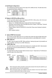
...states of UMA Frame Buffer Size (refer to prevent an electrical short inside the cable connector. - 21 - Dual Display Configurations: This motherboard provides three ports for more information) • Playback software: CyberLink PowerDVD 8.0 or later (Note: Please ensure Hardware Acceleration is compatible... S/PDIF Out Connector This connector provides digital audio out to an external audio system that your device and then remove it from the motherboard. • When removing the cable, pull it side to side to Chapter 2, "BIOS Setup," "Advanced BIOS Features," for video...
...states of UMA Frame Buffer Size (refer to prevent an electrical short inside the cable connector. - 21 - Dual Display Configurations: This motherboard provides three ports for more information) • Playback software: CyberLink PowerDVD 8.0 or later (Note: Please ensure Hardware Acceleration is compatible... S/PDIF Out Connector This connector provides digital audio out to an external audio system that your device and then remove it from the motherboard. • When removing the cable, pull it side to side to Chapter 2, "BIOS Setup," "Advanced BIOS Features," for video...
Manual
Page 23
..., make sure your devices are compliant with the connectors you wish to connect. • Before installing the devices, be sure to the connector on the motherboard. - 23 -
..., make sure your devices are compliant with the connectors you wish to connect. • Before installing the devices, be sure to the connector on the motherboard. - 23 -
Manual
Page 24
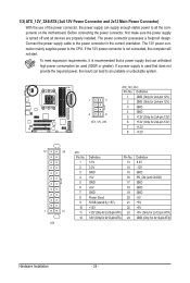
... connector in the correct orientation. Connect the power supply cable to the CPU. If a power supply is turned off and all the components on the motherboard. 1/2) ATX_12V_2X4/ATX (2x4 12V Power Connector and 2x12 Main Power Connector) With the use of the power connector, the power supply can supply enough stable...
... connector in the correct orientation. Connect the power supply cable to the CPU. If a power supply is turned off and all the components on the motherboard. 1/2) ATX_12V_2X4/ATX (2x4 12V Power Connector and 2x12 Main Power Connector) With the use of the power connector, the power supply can supply enough stable...

Manual
Page 25
... in damage to locate pin 1 of a CPU fan with colorcoded power connector wires. 3/4) CPU_FAN/SYS_FAN (Fan Headers) The motherboard has a 4-pin CPU fan header (CPU_FAN)and a 4-pin system fan header(SYS_FAN). The motherboard supports CPU fan speed control, which requires the use of the connector and the floppy disk drive cable. Overheating...
... in damage to locate pin 1 of a CPU fan with colorcoded power connector wires. 3/4) CPU_FAN/SYS_FAN (Fan Headers) The motherboard has a 4-pin CPU fan header (CPU_FAN)and a 4-pin system fan header(SYS_FAN). The motherboard supports CPU fan speed control, which requires the use of the connector and the floppy disk drive cable. Overheating...


