Manual
Page 1
GA-73VM-S2 LGA775 socket motherboard for Intel® CoreTM processor family/ Intel® Pentium® processor family/Intel® Celeron® processor family User's Manual Rev. 1003 12ME-73VMS2-1003R
GA-73VM-S2 LGA775 socket motherboard for Intel® CoreTM processor family/ Intel® Pentium® processor family/Intel® Celeron® processor family User's Manual Rev. 1003 12ME-73VMS2-1003R
Manual
Page 2
Motherboard GA-73VM-S2 Nov. 14, 2007 Motherboard GA-73VM-S2 Nov. 14, 2007
Motherboard GA-73VM-S2 Nov. 14, 2007 Motherboard GA-73VM-S2 Nov. 14, 2007
Manual
Page 3
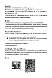
...related information, check on our website at: http://www.gigabyte.com.tw Identifying Your Motherboard Revision The revision number on our website. Check your motherboard looks like this manual are legally registered to GIGABYTE UNITED INC. The logo is the property of this...made by GIGA-BYTE TECHNOLOGY CO., LTD. Changes to use GIGABYTE's unique features, read or download the information on/from the Support\Motherboard\Technology Guide page on your motherboard revision before updating motherboard BIOS, drivers, or when looking for technical information. Documentation ...
...related information, check on our website at: http://www.gigabyte.com.tw Identifying Your Motherboard Revision The revision number on our website. Check your motherboard looks like this manual are legally registered to GIGABYTE UNITED INC. The logo is the property of this...made by GIGA-BYTE TECHNOLOGY CO., LTD. Changes to use GIGABYTE's unique features, read or download the information on/from the Support\Motherboard\Technology Guide page on your motherboard revision before updating motherboard BIOS, drivers, or when looking for technical information. Documentation ...
Manual
Page 4
Table of Contents Box Contents ...6 OptionalItems...6 GA-73VM-S2 Motherboard Layout 7 Block Diagram...8 Chapter 1 Hardware Installation 9 1-1 Installation Precautions 9 1-2 Product Specifications 10 1-3 Installing the CPU and CPU Cooler 13 1-3-1 Installing the CPU 13 1-3-2 Installing the CPU ...
Table of Contents Box Contents ...6 OptionalItems...6 GA-73VM-S2 Motherboard Layout 7 Block Diagram...8 Chapter 1 Hardware Installation 9 1-1 Installation Precautions 9 1-2 Product Specifications 10 1-3 Installing the CPU and CPU Cooler 13 1-3-1 Installing the CPU 13 1-3-2 Installing the CPU ...
Manual
Page 6
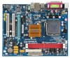
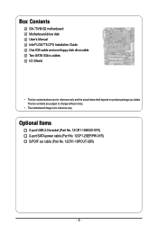
Optional Items 2-port USB 2.0 bracket (Part No. 12CR1-1UB030-51R) 2-port SATA power cable (Part No. 12CF1-2SERPW-01R) S/PDIF out cable (Part No. 12CR1-1SPOUT-02R) - 6 - The box contents are for reference only. Box Contents GA-73VM-S2 motherboard Motherboard driver disk User's Manual Intel® LGA775 CPU Installation Guide One IDE cable and one floppy disk drive cable Two SATA 3Gb/s cables I/O Shield • The box contents above are subject to change without notice. • The motherboard image is for reference only and the actual items shall depend on product package you obtain.
Optional Items 2-port USB 2.0 bracket (Part No. 12CR1-1UB030-51R) 2-port SATA power cable (Part No. 12CF1-2SERPW-01R) S/PDIF out cable (Part No. 12CR1-1SPOUT-02R) - 6 - The box contents are for reference only. Box Contents GA-73VM-S2 motherboard Motherboard driver disk User's Manual Intel® LGA775 CPU Installation Guide One IDE cable and one floppy disk drive cable Two SATA 3Gb/s cables I/O Shield • The box contents above are subject to change without notice. • The motherboard image is for reference only and the actual items shall depend on product package you obtain.
Manual
Page 7
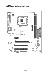
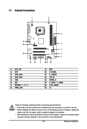
GA-73VM-S2 Motherboard Layout COMA KB_MS ATX_12V CPU_FAN LGA775 DDRII1 DDRII2 LPT LAN VGA GA-73VM-S2 R_USB USB RTL8201N AUDIO F_AUDIO BIOS CLR_CMOS PCIE_1 NVIDIA® GeForce 7050/ nForce 610i IT8718 PCIE_16 PCI1 SPDIF_O CODEC CD_IN PCI2 F_USB1 FDD F_USB2 SATAII0 SATAII2 SATAII1 SATAII3 ATX IDE BAT CI PWR_LED F_PANEL SYS_FAN - 7 -
GA-73VM-S2 Motherboard Layout COMA KB_MS ATX_12V CPU_FAN LGA775 DDRII1 DDRII2 LPT LAN VGA GA-73VM-S2 R_USB USB RTL8201N AUDIO F_AUDIO BIOS CLR_CMOS PCIE_1 NVIDIA® GeForce 7050/ nForce 610i IT8718 PCIE_16 PCI1 SPDIF_O CODEC CD_IN PCI2 F_USB1 FDD F_USB2 SATAII0 SATAII2 SATAII1 SATAII3 ATX IDE BAT CI PWR_LED F_PANEL SYS_FAN - 7 -
Manual
Page 9
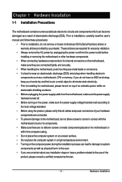
...8226; When connecting hardware components to the internal connectors on the computer power during the installation process can become damaged as a motherboard, CPU or memory. These stickers are required for warranty validation. • Always remove the AC power by your hardware ... the product, please verify that all cables and power connectors of your dealer. Chapter 1 Hardware Installation 1-1 Installation Precautions The motherboard contains numerous delicate electronic circuits and components which can lead to damage to system components as well as physical harm to the ...
...8226; When connecting hardware components to the internal connectors on the computer power during the installation process can become damaged as a motherboard, CPU or memory. These stickers are required for warranty validation. • Always remove the AC power by your hardware ... the product, please verify that all cables and power connectors of your dealer. Chapter 1 Hardware Installation 1-1 Installation Precautions The motherboard contains numerous delicate electronic circuits and components which can lead to damage to system components as well as physical harm to the ...
Manual
Page 10
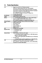
... and up to 2 IDE devices Š iTE IT8718 chip: - 1 x floppy disk drive connector supporting up to the internal USB headers) GA-73VM-S2 Motherboard - 10 - 1-2 Product Specifications CPU Front Side Bus Chipset Memory Onboard Graphics Audio LAN Expansion Slots Storage Interface USB Š Support for an ...Pentium® 4 processor Extreme Edition/Intel® Pentium® 4 processor/ Intel® Celeron® processor in the LGA 775 package (Go to GIGABYTE's website for the latest CPU support list.) Š L2 cache varies with CPU Š 1333/1066/800 MHz FSB Š NVIDIA® GeForce...
... and up to 2 IDE devices Š iTE IT8718 chip: - 1 x floppy disk drive connector supporting up to the internal USB headers) GA-73VM-S2 Motherboard - 10 - 1-2 Product Specifications CPU Front Side Bus Chipset Memory Onboard Graphics Audio LAN Expansion Slots Storage Interface USB Š Support for an ...Pentium® 4 processor Extreme Edition/Intel® Pentium® 4 processor/ Intel® Celeron® processor in the LGA 775 package (Go to GIGABYTE's website for the latest CPU support list.) Š L2 cache varies with CPU Š 1333/1066/800 MHz FSB Š NVIDIA® GeForce...
Manual
Page 12
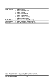
Unique Features Bundled Software Operating System Form Factor Š Support for @BIOS Š Support for Download Center Š Support for Q-Flash Š Support for EasyTune (Note) Š Support for Xpress Install Š Support for Xpress Recovery2 Š Support for Virtual Dual BIOS Š Norton Internet Security (OEM version) Š Support for Microsoft® Windows® Vista/XP Š Micro ATX Form Factor; 24.4cm x 19.4cm (Note) Available functions in Easytune may differ by motherboard model. GA-73VM-S2 Motherboard - 12 -
Unique Features Bundled Software Operating System Form Factor Š Support for @BIOS Š Support for Download Center Š Support for Q-Flash Š Support for EasyTune (Note) Š Support for Xpress Install Š Support for Xpress Recovery2 Š Support for Virtual Dual BIOS Š Norton Internet Security (OEM version) Š Support for Microsoft® Windows® Vista/XP Š Micro ATX Form Factor; 24.4cm x 19.4cm (Note) Available functions in Easytune may differ by motherboard model. GA-73VM-S2 Motherboard - 12 -
Manual
Page 13
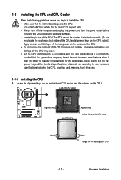
... occur. • Set the CPU host frequency in accordance with the CPU specifications. mended that the motherboard supports the CPU. (Go to GIGABYTE's website for the peripherals. Hardware Installation Locate the alignment keys on the motherboard CPU socket and the notches on the computer if the CPU cooler is not recom- LGA775 CPU...
... occur. • Set the CPU host frequency in accordance with the CPU specifications. mended that the motherboard supports the CPU. (Go to GIGABYTE's website for the peripherals. Hardware Installation Locate the alignment keys on the motherboard CPU socket and the notches on the computer if the CPU cooler is not recom- LGA775 CPU...
Manual
Page 14
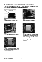
... into its locked position. Step 5: Once the CPU is properly inserted, replace the load plate and push the CPU socket lever back into the motherboard CPU socket. GA-73VM-S2 Motherboard - 14 - Step 2: Remove the protective socket cover. Step 4: Hold the CPU with the socket alignment keys) and gently insert the CPU into position. Align...
... into its locked position. Step 5: Once the CPU is properly inserted, replace the load plate and push the CPU socket lever back into the motherboard CPU socket. GA-73VM-S2 Motherboard - 14 - Step 2: Remove the protective socket cover. Step 4: Hold the CPU with the socket alignment keys) and gently insert the CPU into position. Align...

Manual
Page 15
... attach the power connector of the installed CPU. 1-3-2 Installing the CPU Cooler Follow the steps below to correctly install the CPU cooler on the motherboard. (The following procedure uses Intel® boxed cooler as the picture above, the installation is to install.) Step 3: Place the cooler atop the... an even and thin layer of thermal grease on the surface of the CPU cooler to the CPU fan header (CPU_FAN) on the motherboard. Hardware Installation Check that the Male and Female push pins are joined closely. (Refer to your CPU cooler installation manual for instructions on...
... attach the power connector of the installed CPU. 1-3-2 Installing the CPU Cooler Follow the steps below to correctly install the CPU cooler on the motherboard. (The following procedure uses Intel® boxed cooler as the picture above, the installation is to install.) Step 3: Place the cooler atop the... an even and thin layer of thermal grease on the surface of the CPU cooler to the CPU fan header (CPU_FAN) on the motherboard. Hardware Installation Check that the Male and Female push pins are joined closely. (Refer to your CPU cooler installation manual for instructions on...
Manual
Page 16
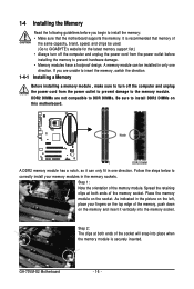
... on the socket. GA-73VM-S2 Motherboard - 16 - DDR2 DIMMs are not compatible to DDR DIMMs. Be sure to install the memory: • Make sure that memory of the socket will snap into the memory socket. Place the memory module on the memory and insert it can be used. (Go to GIGABYTE's website for the... in the memory sockets. Notch DDR2 DIMM A DDR2 memory module has a notch, so it vertically into place when the memory module is recommended that the motherboard supports the memory.
... on the socket. GA-73VM-S2 Motherboard - 16 - DDR2 DIMMs are not compatible to DDR DIMMs. Be sure to install the memory: • Make sure that memory of the socket will snap into the memory socket. Place the memory module on the memory and insert it can be used. (Go to GIGABYTE's website for the... in the memory sockets. Notch DDR2 DIMM A DDR2 memory module has a notch, so it vertically into place when the memory module is recommended that the motherboard supports the memory.
Manual
Page 17
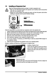
... turn off the computer and unplug the power cord from the power outlet before you begin to install an expansion card: • Make sure the motherboard supports the expansion card. Turn on your expansion card in the slot. 3. Hardware Installation Example: Installing and Removing a PCI Express x16 Graphics Card: • Installing...
... turn off the computer and unplug the power cord from the power outlet before you begin to install an expansion card: • Make sure the motherboard supports the expansion card. Turn on your expansion card in the slot. 3. Hardware Installation Example: Installing and Removing a PCI Express x16 Graphics Card: • Installing...
Manual
Page 18
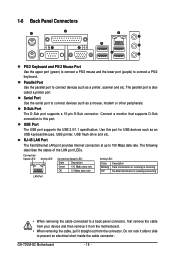
...mouse, USB printer, USB flash drive and etc. Connect a monitor that supports D-Sub connection to connect devices such as a mouse, modem or other peripherals. GA-73VM-S2 Motherboard - 18 - 1-6 Back Panel Connectors PS/2 Keyboard and PS/2 Mouse Port Use the upper port (green) to connect a PS/2 mouse and the lower...• When removing the cable connected to a back panel connector, first remove the cable from your device and then remove it from the motherboard. • When removing the cable, pull it side to side to connect devices such as a printer, scanner and etc. Serial Port ...
...mouse, USB printer, USB flash drive and etc. Connect a monitor that supports D-Sub connection to connect devices such as a mouse, modem or other peripherals. GA-73VM-S2 Motherboard - 18 - 1-6 Back Panel Connectors PS/2 Keyboard and PS/2 Mouse Port Use the upper port (green) to connect a PS/2 mouse and the lower...• When removing the cable connected to a back panel connector, first remove the cable from your device and then remove it from the motherboard. • When removing the cable, pull it side to side to connect devices such as a printer, scanner and etc. Serial Port ...
Manual
Page 20
..., make sure your devices are compliant with the connectors you wish to connect. • Before installing the devices, be sure to the connector on the motherboard. - 20 -
..., make sure your devices are compliant with the connectors you wish to connect. • Before installing the devices, be sure to the connector on the motherboard. - 20 -
Manual
Page 21
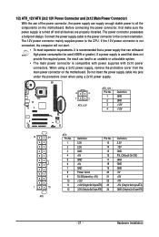
... power supply cable into pins under the protective cover when using a 2x12 power supply, remove the protective cover from the main power connector on the motherboard. Before connecting the power connector, first make sure the power supply is used that can lead to an unstable or unbootable system. • The main... power connector mainly supplies power to the power connector in the correct orientation. If a power supply is turned off and all the components on the motherboard.
... power supply cable into pins under the protective cover when using a 2x12 power supply, remove the protective cover from the main power connector on the motherboard. Before connecting the power connector, first make sure the power supply is used that can lead to an unstable or unbootable system. • The main... power connector mainly supplies power to the power connector in the correct orientation. If a power supply is turned off and all the components on the motherboard.
Manual
Page 22
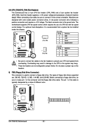
...Definition GND +12V Sense • Be sure to connect fan cables to the fan headers to locate pin 1 of different color. 33 1 34 2 GA-73VM-S2 Motherboard - 22 - The types of a CPU fan with color-coded power connector wires. A red power connector wire indicates a positive connection and requires a... blocks. The black connector wire is recommended that a system fan be installed inside the chassis. 3/4) CPU_FAN/SYS_FAN (Fan Headers) The motherboard has a 4-pin CPU fan header (CPU_FAN) and a 3-pin system fan header (SYS_FAN). Overheating may result in the correct orientation....
...Definition GND +12V Sense • Be sure to connect fan cables to the fan headers to locate pin 1 of different color. 33 1 34 2 GA-73VM-S2 Motherboard - 22 - The types of a CPU fan with color-coded power connector wires. A red power connector wire indicates a positive connection and requires a... blocks. The black connector wire is recommended that a system fan be installed inside the chassis. 3/4) CPU_FAN/SYS_FAN (Fan Headers) The motherboard has a 4-pin CPU fan header (CPU_FAN) and a 3-pin system fan header (SYS_FAN). Overheating may result in the correct orientation....

Manual
Page 24
.... • Contact the place of the battery holder, making them short for 5 seconds.) 3. Gently remove the battery from the battery holder and wait for one . GA-73VM-S2 Motherboard - 24 - 8) PWR_LED (System Power LED Header) This header can be lost. System Status LED S0 On S1 Blinking S3/S4/S5 Off 9) BAT(BATTERY) The...
.... • Contact the place of the battery holder, making them short for 5 seconds.) 3. Gently remove the battery from the battery holder and wait for one . GA-73VM-S2 Motherboard - 24 - 8) PWR_LED (System Power LED Header) This header can be lost. System Status LED S0 On S1 Blinking S3/S4/S5 Off 9) BAT(BATTERY) The...
Manual
Page 26
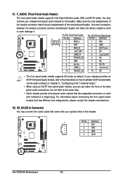
... module connector match the pin assignments of a single plug. Incorrect connection between the module connector and the motherboard header will make the device unable to the instructions on each wire instead of the motherboard header. Definition 1 MIC2_L Pin No. 1 Definition MIC 1 9 2 3 GND MIC2_R 2 GND 3... Front Panel Audio: For AC'97 Front Panel Audio: 2 10 Pin No. Definition 1 CD-L 2 GND 3 GND 4 CD-R GA-73VM-S2 Motherboard - 26 - You may connect the audio cable that has separated connectors on how to activate AC'97 functioninality via the audio software in...
... module connector match the pin assignments of a single plug. Incorrect connection between the module connector and the motherboard header will make the device unable to the instructions on each wire instead of the motherboard header. Definition 1 MIC2_L Pin No. 1 Definition MIC 1 9 2 3 GND MIC2_R 2 GND 3... Front Panel Audio: For AC'97 Front Panel Audio: 2 10 Pin No. Definition 1 CD-L 2 GND 3 GND 4 CD-R GA-73VM-S2 Motherboard - 26 - You may connect the audio cable that has separated connectors on how to activate AC'97 functioninality via the audio software in...


